Abstract
Passenger safety requires that in commercial airplanes hydraulic actuators be powered by fire-resistant hydraulic fluids. As a downside, such fluids are hygroscopic which means that these tend to accumulate humidity from the environment and that the dissolved humidity tends to produce acidity which can corrode all kinds of metallic components inside a hydraulic system. As such damage in safety-critical subsystems is hard to localize and expensive to repair, sensor technologies are required which allow the state of water contamination and fluid degradation to be routinely checked and necessary maintenance actions to be scheduled in a way that causes minimum flight interruptions. The paper reviews progress that has been made in developing such sensor systems and in commissioning these into practical flight operation. Sensor technologies that proved optimally adapted to this purpose are multi-channel non-dispersive (NDIR) systems working in the mid-infrared range. Additional options concern optical absorption sensors working in the near-infrared and visible ranges as well as fluorescence sensors.
1. Introduction
In commercial aircrafts, flats, slats, tail plane fins and landing gears, i.e., all kinds of safety-critical mechanical subsystems, are powered by hydraulic actuators. The reason for using hydraulics is that it can generate large forces at comparatively low weight. As the performance of hydraulic actuators is critically dependent on those fluids that power them, important maintenance issues arise regarding such fluids. Fire-resistant phosphate-ester fluids, which are commonly used in commercial airplanes, are hygroscopic in nature [1,2,3,4] which means that these tend to accumulate humidity from the environment through air-pressurized reservoirs and leaky seals. Absorbed water vapor together with Joule heat, which is generated upon hydraulic actuation, tends to break down the base fluids into smaller molecular fragments and into several kinds of acidic phosphates which are problematic for two reasons: firstly, such fragments support autocatalytic reactions, which speed up the degradation process, and secondly, these tend to corrode all kinds of metallic components inside a hydraulic system, thus generating metallic particle debris. Once caught inside pumps, valves and actuators, such debris can cause severe abrasive damage and ultimately gross mechanical failure.
As such downstream mechanical damage is hard to localize and expensive to repair, the continued performance of hydraulic fluids needs to be ascertained through repeated measurements. Conventionally this is done during C-checks—typically once in a year—by tapping fluid from the pressurized reservoir and by sending the tapped fluid to specialized laboratories where a range of relevant fluid properties can be determined. Depending on these results, either water is withdrawn from the hydraulic fluid and/or the fluid is partially or completely exchanged. A key problem inherent in this approach is that this maintenance-related information typically becomes available with a delay of one week or more, i.e., when the serviced aircraft should normally be back in operation. In case maintenance urgently needs to be done on the fluid, the plane might get grounded in a remote airfield with poor infrastructure, where such maintenance is hard to perform. As such unscheduled maintenance is associated with an interruption of the normal flight schedule and considerable cost to the airline operating this plane such unfavorable situations urgently need to be avoided. Airliners, therefore, have asked for in-plane fluid monitoring systems which allow relevant fluid properties to be measured with a daily or weekly frequency without tapping fluid from the pressurized hydraulic system [5]. Once available, such monitoring systems would allow fluid degradation trends to be established and necessary maintenance activities to be planned and scheduled to occur at times and in locations of the airliner’s choice without seriously interrupting their flight schedules.
In this paper we briefly review the progress that has been made along this line [6,7,8,9,10,11], focusing on the work performed at EADS Innovation Works, the predecessor organization of the current Airbus Central Research & Technology organization. In Section 2 we present a brief introduction into aviation hydraulic fluids, focusing on their preparation, chemical structure, and relevant degradation processes. In Section 3 we present optical absorption data, obtained on a range of widely used hydraulic fluids and spanning over a wide range of photon energies. In this way optical signatures of fluid contamination and fluid degradation have been identified which can be used to advantage in opto-chemical sensor systems. In Section 4, Section 5 and Section 6, state of the art optical fluid sensors and emerging sensor concepts are reviewed. In Section 7 we summarize our findings and make proposals for future research.
2. Hydraulic Fluids and Fluid Degradation
Esters in general are produced by reacting acids (HA) and alcohols (R-OH), yielding as reaction products the esters themselves and reaction water which needs to be withdrawn to obtain the pure product [12]:
HA + R-OH → Ester (A-R) + H2O.
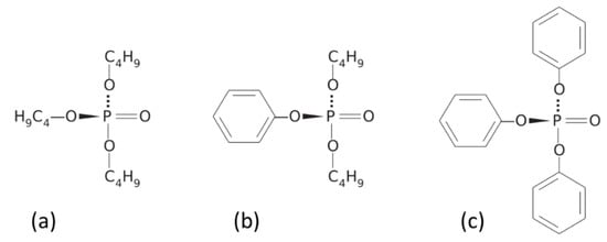
When phosphoric acid, (H3PO4) is used to produce esters, three alcoholic side groups can be bound to a single phosphate core. Depending on the kinds of alcohols used, molecules with aliphatic and aromatic side groups can be obtained as shown in Figure 1.
Figure 1.
Chemical structure of aircraft certified hydraulic fluids; (a) tributyl phosphate; (b) di-butyl phenyl phosphate; (c) triphenyl phosphate [6].
Whereas the phosphate nucleus largely determines the fire resistance of the fluid, other fluid properties such as mass density, viscosity, compressibility, and their respective temperature dependencies are determined by the side groups. The key property of fire resistance of phosphate ester fluids derives from the high electron affinity of the central phosphate cores and their ability to extract electrons from excited electronic states inside the side groups towards the central core. In case of fire and high temperatures, the state of electronic excitation of the phosphate-ester molecules is thereby kept to a minimum and their resilience against oxidative processes is enhanced.
Commercial aviation hydraulic fluids mainly consist of mixtures of tributyl phosphate, di/-butyl phenyl phosphate and triphenyl phosphate [1,2,3] with their mixing ratios depending on the specific kinds of applications envisaged. Whereas these constituents may make up to 99% of the fluid, aviation hydraulic fluids also typically contain several percents of additives such as antioxidants, antiwear- and viscosity improvers and minor amounts of metal deactivators and dyes [1,2,3]. Some of the most widely used kinds of aviation hydraulic fluids is marketed by Solutia Inc. under the brand name Skydrol with their main constituents being listed in Table 1.
Table 1.
Main ingredients in the widely used family of hydraulic fluids marketed under the brand name Skydrol [1,2,3].
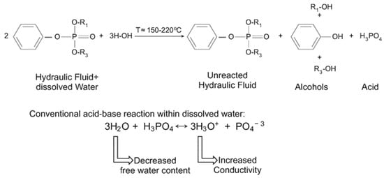
Once water is taken up into an aircraft hydraulic system, either during normal aircraft operation or through leaks that might have occurred during operation, the dissolved water molecules tend to drive back the ester formation reaction (Equation (1)), thus breaking down a fraction of the ester molecules into their component molecules again [12]. This degradation process is illustrated in Figure 2, emphasizing the important fact that the freed phosphate cores together with the dissolved water can form H3O+ ions which can corrode all kinds of metallic components inside the hydraulic system, thus causing metallic particle debris which can damage and obstruct pumps and actuators.
Figure 2.
Chemical reactions following the take-up of water into a phosphate-ester based hydraulic fluid, yielding split-off alcohols and partial phosphates, ultimately producing phosphoric acid and H3O+ ions via reaction with the dissolved water [6].
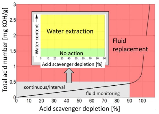
In aviation hydraulic fluids the generation of corrosive hydronium ions is suppressed by epoxide additives (see Table 1) which act as acid scavengers. With these acid scavengers being present, any partial phosphates that are split off from the base molecules by interaction with the dissolved water immediately become trapped by the epoxy additives and a rapid rise in total acid number (TAN) is prevented. Figure 3 shows that this fluid-internal repair process continues up to an acid scavenger depletion level of almost 90%. Within this long period of moderate fluid degradation, any further degradation of the base fluid can be prevented by extracting the dissolved water, typically in an overnight ground stop. The most important message contained in Figure 3 is that once this critical level of acid scavenger depletion has been reached, water contamination and hydrolysis lead to a rapid rise in TAN values which can only be counteracted by performing a much more expensive partial or complete exchange of the fluid. As such a break point in the fluid degradation trend may occur in between two C-checks, it might remain unnoticed for a long time and severe downstream mechanical damage could develop while the airplane is still in operation. In summary, Figure 3 vividly demonstrates the importance of a more or less continuous monitoring of the degradation process, and in particular, of arriving at early and reliable estimates of the remaining acid scavenger reserve.
3. Optical Signatures of Hydraulic Fluid Degradation
Attempting to find optical signatures of fluid contamination and fluid degradation, a large number of fluid samples were prepared [10,11] and contaminated with controlled amounts of water at room temperature and analyzed for their water content using conventional Carl-Fischer titration [13]. Other samples had been heat-treated after water-contamination inside small, sealed glass vessels to induce hydrolysis and acidification. To speed up thermal degradation, boiling was performed at 180 °C for about 6 h, which is equivalent to several months of thermal degradation inside a heavily used aviation hydraulic system [14]. Again, these thermally degraded samples were analyzed for their TAN values using conventional titration with potassium hydroxide (KOH) [12].
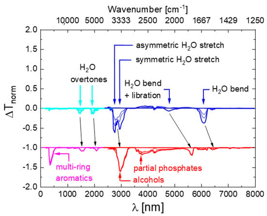
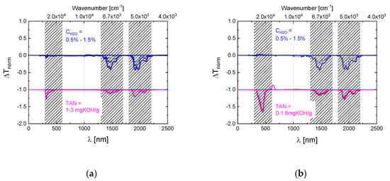
After preparation, the fluids were inserted either into a Fourier-Transform Infra-Red (FTIR) or a Near-Infrared-Visible-Ultraviolet (NIR-VIS-UV) spectrometer and optical transmission spectra were measured over a spectral range extending from about 2.5 to 24 μm in the mid-infrared (MIR) or 200 to 2700 nm (UV-VIS-NIR) wavelength ranges. After measurement, all spectra were normalized to their maximum transmission values which occurred in a wavelength range which proved to be unaffected by water contamination and thermal degradation (). Within such normalized spectra the strongest absorption feature was the C-H stretching vibration of the phosphate ester molecules, which occurred in the vicinity of [15]. In order to emphasize those changes in spectroscopic behavior which occurred due to the water contamination and thermal degradation, difference spectra were generated by subtracting from each measured spectrum the reference spectrum of an undegraded fluid containing 0.2% of H2O. In this way spectra were obtained which do no longer show the dominating and unchanging C-H vibration, but which emphasize very clearly those spectroscopic changes that result from the water contamination and the thermal degradation. Some of those results obtained on water-contaminated and thermally degraded Skydrol LD4 samples are shown in Figure 4. As shown in more detail in Appendix A, similar data were also obtained on other kinds of commercial fluids. Additionally, shown in Figure 4 are assignments to molecular vibration modes which are discussed in more detail in Appendix B and Appendix C.
Figure 4.
Difference spectra as obtained on Skydrol LD4 after controlled contamination with water (top row) and after water contamination and molecular fragmentation (bottom row). The water-contaminated samples contained up to 1.5% H2O, while the degraded ones had TAN-values between 1–3 mg KOH/g as determined by conventional titration. The spectra of the thermally degraded samples were offset by one unit of normalized absorption towards ΔTnorm = −1 for reasons of clarity of presentation.
4. MIR Monitoring of Aviation Hydraulic Fluids
The most straight-forward way of arriving at an opto-chemical sensor system is concentrating, firstly, on those strong ground state absorptions which derive from vibrations of O-H groups which are either parts of dissolved water or split-off alcohols and, secondly, on those that derive from phosphate cores [16] which had lost their hydrocarbon side-groups.
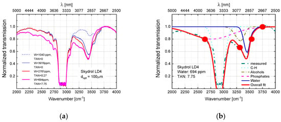
As shown in Figure 5a, water contamination leads to an increase in the O-H absorption strength around 3500 cm−1. Upon fluid degradation, the O-H absorption feature shifts towards lower wavenumbers around 3300 cm−1 as O-H groups, initially bound to dissolved water, become bound to alcohols which had been split off from their phosphate cores. As long as the remaining partial phosphates are trapped by acid scavenger molecules, the broad, lower-energy phosphate absorption feature, left to the dominant C-H absorption of the base molecules, remains small. A strong increase in this feature, however, occurs after all acid scavenger molecules had become consumed. In this event, ongoing fluid degradation causes the TAN value to rise and the phosphate absorption feature to increase in proportion to the low-energy O-H absorption.
Figure 5.
(a) FTIR spectra of Skydrol LD4 samples in different states of water contamination (blue) and fluid degradation (red, magenta) [10,11]. (b) Deconvolution of FTIR spectra into C-H, phosphate- and water-related spectral features. Red circles denote sensor interrogation points used in the sensor prototype described further below [10,11].
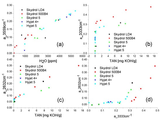
Figure 5b shows the decomposition of a measured MIR fluid transmission spectrum into its constituent parts. In this figure circles also indicate those four spectral positions which are probed by the 4-channel NDIR sensor system prototype described below. As described in more detail in our previous publications [10,11], probing the optical transmission inside these four windows allows the water content, the state of fluid decomposition, and the acidification of the fluid to be quantitatively determined. This capability is also demonstrated in Figure 6. In addition, and most interestingly, by combining the information of the phosphate and the alcohol O-H absorptions, the remaining acid scavenger reserve can be determined and estimates for the remaining fluid life can be obtained [10,11].
Figure 6.
(a) Variation of normalized optical absorption in the 3559 cm−1 water absorption window with the water content remaining in water-contaminated fluid samples after thermal degradation; Variation of the normalized optical absorption inside the 3333 cm−1 alcohol (b) and 2632 cm−1 phosphate absorption windows (c) with the TAN value in the same set of fluids; (d) Correlation of the phosphate and butanol/phenol absorptions in thermally degraded aviation fluids. Above a_3333 = 0.2 a rapid depletion of the acid scavengers is indicated [10,11].
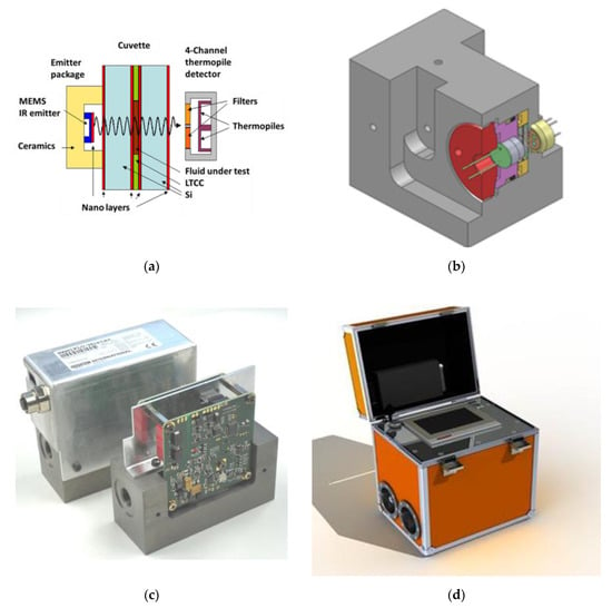
Figure 7 shows images of the developed sensor prototype. Figure 7a,b show the mechanical setup of the sensor system [9,10,11], featuring a thin fluid layer sandwiched between a thermal micro-electromechanical systems (MEMS) emitter [17] and a 4-thermopile sensor array [18,19], covered with narrow-band filters with their transmission windows centered around those four spectral ranges indicated in Figure 5b. In-depth technological information about the thermal emitter, the thermopile array as well as the high-pressure-resistant micro-cuvette are contained in a previous publication of our project partners [20]. Highlight of these developments was the successful fabrication of micro-structured multi-wafer stacks consisting of layers of infrared-transparent silicon and micro-structured low-temperature-cofired (LTCC) ceramic wafers to make up high-pressure resistant microcuvettes. Figure 7c shows a fully assembled MIR sensor system prototype containing these micro-components. In the final phases of the BMBF NAMIFLU project [21] these prototypes were successfully tested inside the Airbus Toulouse hydraulics test rig at internal pressures up to 400 bar. Such sensors were also successfully implemented inside the Ground Lab [9,22] shown in Figure 7d. This Ground Lab has been developed for Airbus by the hydraulics system provider HYDAC, containing the MIR sensor prototype shown in Figure 7c and an additional particle counter. Currently, such systems are being used to tap fluid from existing airplanes during ground stops and to provide rapid assessments of the chemical degradation and of the particle contamination of hydraulic fluids on ground without the need for time-consuming off-site analysis in distant laboratories. In this way maintenance activities can be speeded up and flight interruptions kept to a minimum.
Figure 7.
(a) Micro-cuvette containing the fluid under test and fitted in between a MEMS IR emitter and a 4-thermopile sensor array with narrow band filters transparent at the wavelengths indicated in Figure 5b [10,11]. (b) Mechanical set-up containing the MEMS IR emitter, the micro-cuvette (yellow) and the thermopile detector array inside a common metal block (grey) that can withstand the high pressures inside aviation hydraulic systems [10,11]. (c) Fully assembled MIR sensor system featuring the internal electronics and fluidic connectors [10,11]. (d) HYDAC Ground Lab for on-site hydraulic fluid monitoring on airfields containing the MIR sensor system shown in (a–c), and an additional particle contamination detector [9,22].
A downside of the MIR monitoring system displayed in Figure 7 is that it works in a spectral range in which strong ground state absorptions dominate and where consequently sensor-internal optical absorption paths need to be kept very short (). MIR monitoring systems therefore feature large flow resistances which preclude their direct insertion into aircraft hydraulic systems. The much-desired aircraft-internal use only becomes possible when the MIR systems are positioned inside bypass sections which can be shut-off from the aircraft hydraulic system during flight. As such bypass sections require extra space and contribute additional weight, the present MIR systems can only be incorporated into newly produced aircrafts.
5. Optical Absorption Monitoring of Aviation Hydraulic Fluids in the Visible and Near Infrared Ranges
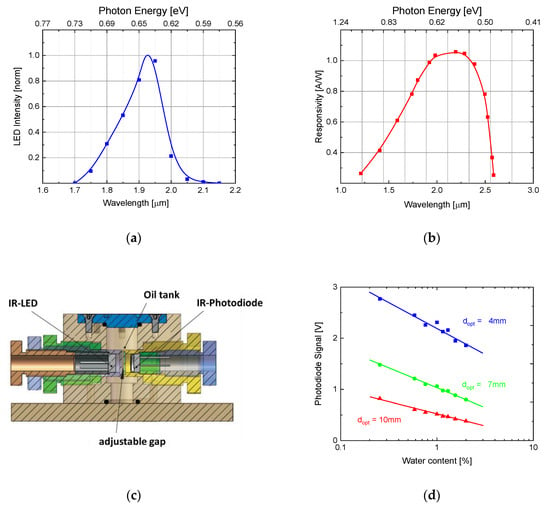
Considering the problem of flow resistance in MIR systems, optical absorption monitoring in the near infrared and visible ranges appears attractive. Optical absorption in these shorter wavelength ranges is much smaller and larger sensor-internal optical paths become possible. In order to assess this possibility, we show in more detail in Figure 8 those changes upon water contamination and thermal degradation in the short-wavelength region that occur in two widely used hydraulic fluids, i.e., Skydrol LD4 and HYJET V.
Figure 8.
(a) Difference spectra of water-contaminated and thermally degraded Skydrol LD4 in the NIR and VIS ranges (dopt = 1 cm) [6]. (b) Difference spectra of water-contaminated and thermally degraded HYJET V in the NIR and VIS ranges (dopt = 1 cm) [6].
Whereas in both fluids water-related overtone absorptions of dissolved water of similar size and spectral positions can be observed, significant shifts of these absorption features towards longer wavelengths upon acidification cannot be detected. Absent also are overtone replica of the very broad phosphate absorption feature in the MIR. TAN-related absorptions, however, can be observed at optical wavelengths smaller than . Unlike the water absorption features, these latter changes in the VIS and UV ranges are very fluid dependent. As will become evident from the results presented in Section 6 and in Appendix C, the fluid-dependence of these latter features derives from the fact that different fluids contain different concentrations of esters with aromatic side groups. Very simple and effective water contamination sensors with large internal optical paths, however, can be built using commercially available NIR LEDs and NIR detectors, emitting and receiving in the ranges of water overtone absorptions. This latter capability is demonstrated in Figure 9.
Figure 9.
(a) Emission spectrum of commercial NIR-LED (IR S-LED 1.94; Roithner) [6]. (b) Spectral sensitivity of commercial NIR photodiode (InGaAs) (FGA 20 Thorlabs) [6]. (c) Cuvette for sensor investigation tests featuring screw-in MEMS emitter and receiver elements allowing for experiments with variable optical gap lengths [6]. (d) Variation of IR transmission of Skydrol LD4 with increasing water content as measured with the test set-up of Figure 9c and the optical components of (a,b) at a wavelength of λ = 1.94 µm and at different absorption path lengths [6].
High-pressure resistant versions of water contamination sensors can easily be produced using the technology already developed for the MIR systems described in Section 4 and described in more detail in ref. [20]. With their wider internal optical path lengths, however, NIR sensors can be directly placed inside existing hydraulic lines and positioned close to those components, i.e., pumps and actuators, where Joule heat is generated and where hydrolysis reactions are likely to take place. Measuring the local temperature rise during actuation at these spots, the generated Joule heat can be obtained by integration and the heat input into the water-contaminated fluid can be used to estimate the volume densities of base fluid molecules that are likely to have been degraded and the amounts of acid scavenger molecules that had been consumed in counteracting the increase in free phosphates [23]. Such sensors may find applications in innovative aircraft actuation systems which replace much of the conventional hydraulics by electronics and which leave the sole responsibility of generating mechanical power to distributed hydraulic power amplifiers, which contain besides the hydraulic actuators themselves also small dedicated hydraulic reservoirs with pumps and associated health monitoring systems.
6. Fluorescence Monitoring of Aviation Hydraulic Fluids
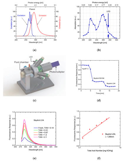
Further exploring the possibility of sensing fluid properties in addition to the water content using small light-weight sensors with large internal light paths, we have performed fluorescence experiments on pure and thermally degraded fluid samples. Key motivation for such experiments was that aviation hydraulic fluids contain ester molecules with phenolic side groups as shown in Figure 1, which as free molecules tend to fluoresce as these become excited with UV light [24].
The property of fluorescence emission is illustrated in Figure 10a, which shows fluorescence excitation and emission spectra of pure phenol. For comparison, Figure 10b shows an optical absorption spectrum of Skydrol LD4, which also shows a strong phenolic absorption at around . Additionally, shown in this graph is the peak emission wavelength of those UV-LEDs that had been used in the fluorescence measurement setup of Figure 10c. Using this setup, the fluorescence response to a range of different hydraulic fluids was tested and which were subsequently flown through its fluid chamber. As expected, the individual fluids responded with different levels of fluorescence light as these contained different concentrations of esters with aromatic side groups. Figure 10e,f show that the fluorescence response significantly increases as fluids become thermally degraded and as their TAN values are increased. This result indicates that breaking aromatic side groups free from their parent phosphate cores increases their excited state lifetimes, and thus makes them more likely to undergo radiative recombination. As, however, this increase in fluorescence does arise from freed aromatic side groups and not from the bare phosphate cores themselves, the observed fluorescence increase is more an indicator of thermal fluid degradation rather than a reliable measure of the TAN value itself.
Figure 10.
(a) Photo excitation and emission spectra of free phenol molecules [24]. (b) Optical absorption spectrum of Skydrol LD4 [6]. Arrows indicate the peak emission of the UV LEDs that were used in the fluorescence setup of Figure 10c. (c) Test setup for fluorescence measurements on aviation hydraulic fluids featuring four UV LEDs emitting at and a photo-multiplier tube [6]. (d) Fluorescence response of undegraded aviation hydraulic fluids with different aromatic contents [6]. (e) Fluorescence spectra of Skydrol LD4 degraded up to increasingly larger TAN values [6]. (f) Fluorescence response of Skydrol LD4 degraded up to increasingly larger TAN values and as observed with the test setup of (c) [6].
7. Achievements and Possible Ways Forward
In our work on aviation hydraulic fluids, we have been able to identify a set of optical features that allow the water content, the presence of thermal degradation products, and the TAN value of phosphate-ester hydraulic fluids to be assessed by purely optical means. Specifically, and as demonstrated in more detail in the Appendices, we could show that these features are universally present in all kinds of commercially available hydraulic fluids which is a huge advantage as in practical aircraft operation hydraulic fluids may be topped up with or exchanged by other brands of commercial fluids in case fluid maintenance needs to be done. With such universal features at hand, opto-chemical sensor technologies are in reach which allow for a continuous monitoring of relevant fluid properties without tapping fluid from pressurized hydraulic reservoirs and of sending samples to distant laboratories for off-site chemical analysis. With the help of online fluid monitoring, fluid degradation trends can be monitored during normal aircraft operation and necessary maintenance activities be scheduled to occur at routine ground stops without interrupting normal flight schedules. In this way, an important part of aircraft maintenance can be aligned with the general industry trend of replacing interval-based and corrective maintenance procedures by predictive and proactive procedures [25,26,27,28].
Among those opto-chemical sensor technologies which had been developed so far, NDIR sensors working in the MIR range have progressed to the highest level of maturity [10,11]. By probing the IR transmittance of aviation hydraulic fluids at four different wavelengths, such sensors allow all maintenance-relevant fluid properties, i.e., water content, thermal fluid degradation, TAN value and remaining acid scavenger reserve, to be determined with temporal frequencies much higher than in currently used aircraft maintenance schemes. A downside of the present MIR monitoring systems, however, is that due to the strong optical absorption in the MIR range, these feature small internal light paths (), much smaller than the internal diameters of hydraulic lines inside commercial airplanes (), and that these therefore can only be operated inside bypass lines which can be shut off during flight.
In order to move closer to the requirements of predictive maintenance concepts of continuously monitoring machine data, of sending them via internet to the machine manufactures and for enabling the manufacturers to send out service recommendations, future sensor developments should aim at removing flow restrictions and to allow sensor use during normal machine operation. A first step into this direction becomes possible by making use of the NIR water monitoring sensors described in Section 5. When such flow-through sensors are directly placed close to the hydraulic actuators where Joule heat is generated and where fluid degradation takes place, the generated heat can be determined from local temperature rise data and estimates of the ensuing fluid degradation and acid scavenger consumption can be obtained by calculation, making use of the known water contamination levels inside the fluid. With regard to the present state of the art, it is relevant to note that such concepts can be turned to reality by completely relying on sensor and electronics hardware which is already commercially available.
Aiming at flow-through sensory capabilities beyond water monitoring, additional research is required. Looking towards the future and considering the proven potential of MIR monitoring systems, developing MIR monitoring systems based on total-internal-reflection (ATR) geometries is a very interesting option. ATR is a well-established laboratory technique, which is routinely used in the analysis of fluid samples and which is also increasingly used in the sensors field [29,30,31,32,33,34,35,36,37]. The attractivity of the ATR technology is that it uses light which is evanescently coupled from a prism or a grating into a thin surface layer of the fluid to be tested, leaving the rest of the fluid unaffected. Very interestingly, an ATR sensor system with an architecture very similar to the MIR sensor system described in Section 4 has been developed by Geörg et al. [32,33] for the analysis of chemical reaction mechanisms. Further interesting developments are MEMS components for the realization of ATR sensor systems such as silicon microgroove ATR mirrors [34,35] and micromachined Fabry-Perot spectrometers [36,37] which potentially allow discrete multi-channel sensor systems to be turned into full-scale micro spectrometer systems.
Further interesting options are fluorescence sensors. In Section 6 we have demonstrated that aviation hydraulic fluids feature an intrinsic fluorescence which derives from the aromatic side groups attached to phosphate-ester molecules. As described there, a downside of this intrinsic fluorescence is that its magnitude is very fluid-dependent and that it increases as phosphate-ester molecules become broken down during fluid degradation. Further, as the fluorescence of detached aromatic side groups does not provide a direct measure of the number of partially and fully depleted phosphates, reliable measurements of the fluid TAN cannot be obtained from observations of the intrinsic fluorescence. Dealing with this problem, the Orellana group at the University of Madrid has investigated sensors which measure changes in the extrinsic fluorescence of transition-metal-based complexes upon interaction with fluid molecules. As described in detail in a review article by this group [38], a number of luminescent sensors has been developed which are of potential interest in various aeronautic fields, including hydraulic fluid monitoring. Recently, our own group has been investigating fluorescence sensors, which use GaN/InGaN nanowire arrays on silicon and sapphire substrates as luminescent materials. As described in some of our recent papers [39,40,41,42], such nanowire arrays respond with fluorescence changes when immersed into fluids with different pH values. Additionally, it has been observed that such nanowire arrays exhibit a quenching response when exposed to oxidizing gases (O2, NO2, O3) and an enhancing response when exposed to water vapor. Although not systematically tested in hydraulic fluids, these latter results indicate that such arrays will exhibit a quenching response upon interaction with partially and fully depleted phosphates and an enhancing response when interacting with dissolved water. As partial phosphates and dissolved water molecules are likely to coexist, fluorescence signals might get fully or partially compensated. Additionally, the level of extrinsic fluorescence emitted from the GaN/InGaN nanowire transduces might get superimposed by the fluid-dependent levels of intrinsic fluorescence emitted from those aromatic side groups that had been broken free from their phosphate cores.
In summary, intensive research efforts are still necessary to arrive at fully functional flow-through sensor systems. Whereas in the case of ATR systems the challenges are more on the engineering side of incorporating ATR coupling elements into high-pressure resistant micro-cuvettes, the challenges with fluorescence sensors are more likely on the side of alleviating cross-sensitivity and chemical stability issues of fluorescent layers.
Author Contributions
A.H. and G.M. had been managers of research projects at EADS Innovation works (predecessor of Airbus Central Research & Technology) devoted to the development of fluid sensor technologies. S.P. performed his PhD work on hydraulic fluid monitoring. All authors have read and agreed to the published version of the manuscript.
Funding
The authors gratefully acknowledge financial support under the EU project SuperSkysense (FP6-AEROSPACE 30863) and the BMBF project NAMIFLU (16SV5357).
Acknowledgments
The authors benefitted from discussions and support from colleagues at EADS, from Volker Baumbach (AIRBUS Bremen), Delphine Hertens (AIRBUS Toulouse) and Thierry Lemettais and Francois Pradat, both from Airbus Group Innovations France. Angelika Hackner (spectroscopic measurements), Wolfgang Legner (sensor system integration) and Volker Hechtenberg (electronics) contributed significantly to the realization of the sensor technologies described in this work.
Conflicts of Interest
The authors declare no conflict of interest.
Appendix A. Difference Spectra of Widely Used Aviation Hydraulic Fluids
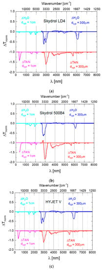
To assess the general usefulness of the optical monitoring approach, spectroscopic measurements on several widely employed aviation hydraulic fluids were performed. The difference spectra derived from these data are presented in Figure A1a–c below.
Figure A1.
Difference spectra as obtained on SKYDROL LD4 (a), SKYDROL 500B4 (b) and HYJET V (c) after controlled contamination with water (blue curves) and after water contamination and molecular fragmentation (red curves). The water-contaminated samples contained up to 1.5% H2O, while the degraded ones had TAN-values between 1 and 3 mg KOH/g as determined by titration. The water- and TAN-spectra have been offset by 1 unit in normalized transmission from for reasons of clarity of presentation.
Appendix B. Assignment of Observed Optical Features to Molecular Vibration Modes
The data in Appendix A show that, independent of the special kind of fluid, remarkably similar spectral features exist which signify water contamination, fluid degradation, and raised TAN values. Turning to the case of water contamination at room temperature first, we note that in the absence of thermal agitation a reaction of the dissolved water molecules with the phosphate-ester base fluids is unlikely to occur. As the dissolved water molecules largely retain their molecular identity, water molecules solvated in hydraulic fluid are expected to exhibit the same vibrational properties as water molecules dissolved inside liquid water. Due to the different molecule-background interactions in the phosphate-ester solvent, however, H2O absorption features will be shifted away from their liquid water spectral positions. This expectation is confirmed by the data summarized in Table A1, which compares the spectral positions of some of the key vibrational features in liquid water [43] to those observed in water contaminated Skydrol LD4. This comparison clearly indicates that all key vibrational features of liquid water are retained in water contaminated Skydrol LD4 and that the associated wavelength shifts never exceed 3–4% of the wavelengths of the respective water absorption features. The data in Appendix A show that these arguments apply equally well also to a wider range of phosphate-ester fluids.
Table A1.
Wavelengths of vibrational features in liquid water (column 3) and of water molecules dissolved in Skydrol LD4 (column 4). Columns 5 and 6 report the corresponding wavelength shifts.
Table A1.
Wavelengths of vibrational features in liquid water (column 3) and of water molecules dissolved in Skydrol LD4 (column 4). Columns 5 and 6 report the corresponding wavelength shifts.
| Water Vibration Feature | λH2O [nm] | λSkydrol_H2O [nm] | Δλ [nm] | Δλ/λH2O [%] | |
|---|---|---|---|---|---|
 | Bend ν2 | 6080 | 6099 | 19 | 0.3 |
 | Combination Bend ν2+L2 | 4650 | 4791 | 141 | 3.03 |
 | Symmetric Stretch ν1 | 3050 | 2952 | −98 | −3.21 |
 | Asymmetric stretch ν3 | 2870 | 2766 | −104 | −3.62 |
| Combination | aν1 + ν2 + bν3. a + b = 1 | 1900 | 1917 | 17 | 0.89 |
| Combination | aν1 + bν3. a + b = 2 | 1470 | 1471 | 1 | 0.07 |
Turning to the optical signatures of acid samples (TAN > 1), Figure A1 demonstrates that most of the observed TAN features appear to be long-wavelength-shifted replica of their parent water absorption ones. Exceptions to this rule are the extremely broad MIR absorption features from about to and the much narrower VIS/UV features in the vicinity of . For the specific example of Skydrol LD4, the corresponding wavelengths and wavelength shifts are listed in Table A2.
Table A2.
Wavelengths of water vibrational features in Skydrol LD4 (column 2) as compared to those vibrational features that arise after water contamination and thermal degradation (column 3). Columns 4 and 5 list the respective wavelength shifts. While most features derive from parent water vibrational features, those in italic letters are degradation and/or TAN specific.
| Skydrol LD4 Vibrational Features | λSkydrol_H2O [nm] | λSkydrol_acidified [nm] | Δλ [nm] | Δλ/λ [%] |
|---|---|---|---|---|
| Bend ν2 | 6099 | 6416 | 317 | 5.2 |
| Combination Bend ν2 + L2 | 4791 | 5635 | 844 | 14.98 |
| Partial phosphates PO-H stretch POH comb. | - | (broad) 3500–5500 | - | - |
| Symmetric Stretch ν1 | 2952 | 3773 | 821 | 27.81 |
| Asymmetric stretch ν3 | 2766 | 2979 | 213 | 7.70 |
| Combination aν1 + ν2 + bν3. a + b = 1 | 1917 | 2080 | 163 | 8.50 |
| Combination aν1 + bν3. a + b = 2 | 1471 | 1518 | 47 | 3.20 |
| Aromatic decay products | - | 361 | - | - |
An important aspect of the fluid degradation process is that it conserves the numbers of O-H bonds during the degradation process. As illustrated in Figure A2 all O-H bonds are initially associated with dissolved water, and with split-off alcohols and partial phosphates after hydrolysis has taken place. As in this final state all O-H bonds are bound to larger-mass backbone molecules than before, a long-wavelength-shift of the water O-H vibrational feature is expected [44].
Figure A2.
Exchange of water- into phenol/butanol - bonded OH groups and partial phosphates as dissolved water is used up in molecular fragmentation events. A shift in the resonance frequency occurs as the force constants (bond strength) and the reduced masses of the molecular oscillators are changed [44].
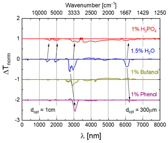
In order to test the validity of this interpretation, Skydrol LD4 samples had been contaminated with 1% butanol or 1% phenol, i.e., typical fragmentation products which are likely to emerge from the degradation reactions sketched in Figure 2 and which had been confirmed in gas chromatographic analyses of degraded aviation hydraulic fluids [14]. The difference spectra in Figure A3 clearly reveal that butanol and phenol addition leads to strong O-H absorption features slightly long-wavelength-shifted with regard to the main stretching vibrations of dissolved water. Interestingly also, all other O-H vibrational features, which can be detected in water-contaminated Skydrol LD4, are no longer observed.
Figure A3.
Difference spectra of phenol, butanol, and water contaminated SKYDROL LD4 as measured relative to a reference specimen containing 0.2% H2O. The top panel displays a spectrum of phosphoric acid that contains an amount of water that unavoidably comes with the H3PO4.
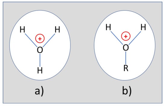
The missing O-H features, however, do turn up as small amounts of H3PO4 are added. As liquid H3PO4 unavoidably contains small quantities of water (~15%), we attribute the re-appearance of the missing O-H features to H3O+ ions, which form as the liquid H3PO4 undergoes electrolytic dissociation together with the concomitantly introduced water. In this way dissolved H3O+ ions form as sketched in Figure A4a. In case degradation products like butanol and phenol are simultaneously present, the OH groups in the split-off alcohols can get protonated, forming molecular end groups as shown in Figure A4b. As these end groups effectively represent H3O+ ions tightly bound to heavy hydrocarbon backbones, the H-O-H end groups remain with the same kinds of vibrational degrees of freedom as the dissolved H3O+ ions in Figure A4a. Due to their larger effective masses, however, these covalently bonded H-O-H end groups will exhibit lower vibrational frequencies as evidenced in Table A2.
Figure A4.
(a) H3O+ ion dissolved in a phosphate-ester fluid; (b) split-off hydrocarbon side group after capture of a proton from an acid partial phosphate.
The broad absorption feature extending from about 3500 to 5000 nm, which increases as H3PO4 is added, can be explained by stretching vibrations of OH-groups with strong hydrogen bonds [16]. As similar bonds will also prevail in all kinds of partial phosphates, this broad feature appears to be the most useful one for a direct spectroscopic determination of the TAN value.
A final important point, illustrated by Figure A3, is that the deliberate contamination of pure Skydrol LD4 with fluid degradation products does not provide any clue to the strong UV-VIS features that occur upon thermal degradation and in the presence of enhanced TAN values (see Figure A1a–c). The strong UV-VIS absorption therefore needs to be attributed to a molecular species that is formed from the original decay products through one or several thermally activated steps. As argued in Appendix C, we believe that these entities consist of multi-ring aromatic species, which had been formed by self-association of split-off phenyl groups and which are able to absorb in the short-wavelength visible and long-wavelength UV ranges.
Appendix C. UV-VIS Absorption of Single- and Multi-Ring Aromatic Species
Commercial aviation hydraulic fluid base stocks mainly consist of mixtures of tributyl phosphate, di/-butyl phenyl phosphate and triphenyl phosphate, with the specific mix depending on the aviation hydraulic fluid product [1,2,3].
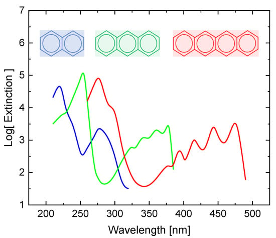
As described in the main text, thermal degradation of the base fluid splits off the hydrocarbon side groups from their parent phosphate cores. Aliphatic C-H side groups in turn will only absorb UV light with wavelengths smaller than 200 nm [45]. A notable exception is aromatics, which contain conjugated C-C bonds arranged in a ring form. As these conjugated systems form delocalized electron systems, smaller HOMO-LUMO splittings result as the size of the delocalized electron systems increases [46]. While phenyl side groups by themselves will hardly absorb light with wavelengths longer than (Figure 10a), larger aromatic aggregates exhibit smaller HOMO-LUMO splittings with optical absorption tails extending out into the VIS range (Figure A5). The comparison in this latter Figure suggests that optical absorption in the VIS range requires self-association of at least four aromatic rings [47]. Interestingly, such cases of self-association have been observed with phenols dissolved in various hydrocarbon solvents [48]. As such association processes are likely to require a significant amount of thermal activation, such molecular entities can only be expected after a prolonged time at elevated temperatures or relatively short times at high temperature. Furthermore, as different hydraulic fluids carry different numbers of phenyl side groups on their center phosphate groups, the probability of occurrence of multi-ring aromatic degradation products is expected to be highly fluid-dependent and also dependent on the use profile of the particular fluids.
References
- Churchill, J. The Skydrol Story; Kindle Edition; 2012. Available online: https://www.amazon.com/Skydrol-Story-John-Churchill-ebook/dp/B00KGWI04K (accessed on 10 December 2020).
- Skydrol™ Aviation Hydraulic Fluids. Available online: https://www.skydrol.com (accessed on 10 December 2020).
- Totten, G.E.; De Negri, V.J. Handbook of Hydraulic Fluid Technology, 2nd ed.; CRC Press Inc.: Boca Raton, FI, USA, 2011; ISBN 978-1-4200-8526-6. [Google Scholar]
- Okazaki, M.E.; Abernathy, S.M.; Laurent, J.W. Hydrolysis of Phosphate-Based Aviation Hydraulic Fluids. J. Synth. Lubr. 1993, 10, 107–118. [Google Scholar] [CrossRef]
- Hertens, D.; Baumbach, V.; (Airbus Industries). Private communication, 2010.
- Paul, S. Optochemical Sensor Systems for Aerospace Applications. Ph.D. Thesis, Justus-Liebig-University, Giessen, Germany, 2014. [Google Scholar]
- Paul, S.; Legner, W.; Krenkow, A.; Müller, G.; Lemettais, T.; Pradat, T.; Hertens, D. Chemical Contamination Sensor for Phosphate Ester Hydraulic Fluids. Int. J. Aerosp. Eng. 2010, 2010, 156281. [Google Scholar] [CrossRef]
- Paul, S.; Legner, W.; Hackner, A.; Baumbach, V.; Müller, G. Multi-Parameter Monitoring System for Hydraulic Fluids. Tech. Mess. 2011, 78, 260–267. [Google Scholar] [CrossRef]
- Helwig, A.; Müller, G.; Rausch, J.; Luther, R.; Bley, T.; Steffensky, J.; Mannebach, H. Applikationsnahe Erprobung und Weiterentwicklungsperspektiven eines Infrarot-basierten Sensorsystems für die Fluidik—Assessment of an Infrared-Based Sensor System for Fluid Monitoring Applications. In Proceedings of the AMA Conference, Nürnberg, Germany, 4 June 2014. [Google Scholar]
- Helwig, A.; Müller, G.; Bley, T.; Steffensky, J.; Mannebach, H. An optoelectronic monitoring system for aviation hydraulic fluids. In Proceedings of the Procedia Engineering, EUROSENSORS 2015, Freiburg, Germany, 6–9 September 2015. [Google Scholar]
- Bley, T.; Steffensky, J.; Mannebach, H.; Helwig, A.; Müller, G. Degradation monitoring of aviation hydraulic fluids using non-dispersive infrared sensor systems. Sens. Actuators B Chem. 2016, 224, 539–546. [Google Scholar] [CrossRef]
- Christen, H.R. Grundlagen der Allgemeinen und Anorganischen Chemie; Salle+Sauerländer: Frankfurt, Germany; Berlin, Germany; München, Germany, 1982; ISBN 3-7935-5394-9. [Google Scholar]
- Fischer, K. Neues Verfahren zur maßanalytischen Bestimmung des Wassergehaltes von Flüssigkeiten und festen Körpern. Angew. Chem. 1935, 48, 394–396. [Google Scholar] [CrossRef]
- Lemettais, T.; Pradat, T.; Hertens, D. (EADS Innovation Works France, Airbus Industries, Toulouse). Private communication.
- Table of IR Absorptions. Available online: https://webspectra.chem.ucla.edu/irtable.html (accessed on 10 December 2020).
- Aslin, R.E.; Denisov, G.S.; Poplevchenkov, D.N.; Tokbadze, K.G.; Velikanova, T.Y. IR v(OH) Band and Dimerization of Phosphorus Acids in the Gas Phase and Solid State. Pol. J. Chem. 2002, 76, 1223–1231. [Google Scholar]
- Müller, L.; Käpplinger, I.; Biermann, S.; Brode, W.; Hofmann, M. Infrared emitting nanostructures for highly efficient micro hotplates. J. Micromech. Microeng. 2014, 24, 035014. [Google Scholar] [CrossRef]
- Available online: https://www.microhybrid.com/de/produkte/thermische-ir-detektoren/ (accessed on 10 December 2020).
- Dillner, U.; Kessler, E.; Meyer, H.G. Figures of merit of thermoelectric and bolometric thermal radiation sensors. J. Sens. Sens. Syst. 2013, 2, 85–94. [Google Scholar] [CrossRef]
- Müller, L.; Günschmann, S.; Fischer, M.; Müller, J.; Hoffmann, M.; Käpplinger, I.; Brode, W.; Magi, A.; Biermann, S.; Pignanelli, E. Entwicklung und Optimierung mikrotechnischer Silicium- und Keramikkomponenten zur Realisierung eines Fluidiksensors - Development and optimization of a fluidic sensor system based on silicon and ceramic microtechnology components. In Proceedings of the Proc. AMA Conference, Nürnberg, Germany, 4 June 2014. [Google Scholar]
- NAMIFLU (BMBMF) Final Report. Available online: https://www.tu-ilmenau.de/mne-et/projekte/namiflu/ (accessed on 10 December 2020).
- Aircraft Hydraulic GroundLab AHG. Available online: https://www.hydac.com.br/wp-content/uploads/e-76670-ahg-en-2016-03-01.pdf (accessed on 10 December 2020).
- Behr, R.; Baumbach, V. Model Based Aerospace Hydraulic Fluid Lifetime Prognostics. In Proceedings of the International Conference on Recent Advances in Aerospace Actuation Systems and Components, Toulouse, France, 5–7 May 2010. [Google Scholar]
- Available online: https://www.sciencedirect.com/book/9780120926565/handbook-of-fluorescence-spectra-of-aromatic-molecules (accessed on 11 December 2020).
- Available online: https://en.wikipedia.org/wiki/Predictive_maintenance (accessed on 11 December 2020).
- Mobley, R.K. (Ed.) An Introduction to Predictive Maintenance; Butterworth-Heinemann: Oxford, UK, 2002. [Google Scholar] [CrossRef]
- Levitt, J. Complete Guide to Preventive and Predictive Maintenance, 2nd ed.; Industrial Press Inc.: New York, NY, USA, 2011; ISBN1 0831134410. ISBN2 978-0831134419. [Google Scholar]
- Lughofer, E.; Sayed-Mouchaweh, M. (Eds.) Predictive Maintenance in Dynamic Systems—Advanced Methods, Decision Support Tools and Real-World Applications, 1st ed.; Springer: Berlin/Heidelberg, Germany; New York, NY, USA, 2019; ISBN 978-3-030-05645-2. [Google Scholar]
- Harrick, N.J. Internal Reflection Spectroscopy; John Wiley & Sons Inc.: Hoboken, NJ, USA, 1967; ISBN 0-470-35250-7. [Google Scholar]
- Milosevic, M. Internal Reflection and ATR Spectroscopy; John Wiley & Sons, Inc.: Hoboken, NJ, USA, 2012; Print ISBN 9780470278321, Online ISBN 9781118309742. [Google Scholar] [CrossRef]
- Vigano, C.; Ruysschaert, J.-M.; Goormaghtigh, E. Sensor Applications of Attenuated Total Reflection Infrared Spectroscopy. Talanta 2005, 65, 1132–1142. [Google Scholar] [CrossRef] [PubMed]
- Geörg, D.; Schalk, R.; Methner, F.J.; Beuermann, T. MIR-ATR sensor for process monitoring. Meas. Sci. Technol. 2015, 26, 6. [Google Scholar] [CrossRef]
- Geörg, D. Entwicklung eines MIR-ATR-Sensors zur Prozesskontrolle in der Chemischen Industrie und Biotechnologie. Ph.D. Thesis, Technical University of Berlin, Berlin, Germany, 2017. [Google Scholar]
- Morhart, T.A.; Read, S.T.; Wells, G.; Jacobs, M.; Rosendahl, S.M.; Achenbach, S.; Burgess, I.J. Micromachined multigroove silicon ATR FT-IR internal reflection elements for chemical imaging of microfluidic devices. Anal. Methods 2019, 11, 5776–5783. [Google Scholar] [CrossRef]
- Haas, J.; Müller, A.; Sykora, L.; Mizaikoff, B. Analytical performance of μ-groove silicon attenuated total reflection waveguides. Analyst 2019, 144, 3398–3404. [Google Scholar] [CrossRef] [PubMed]
- Ebermann, M.; Neumann, N.; Hiller, K.; Seifert, M.; Meinig, M.; Kurth, S. Tunable MEMS Fabry-Pérot filters for infrared microspectrometers: A review. In MOEMS and Miniaturized Systems XV; Piyawattanametha, W., Park, Y.-H., Eds.; SPIE: Bellingham, DC, USA, 2016. [Google Scholar] [CrossRef]
- Ghoname, A.; Sabry, Y.; Anwar, M.; Khalil, D. Attenuated total reflection (ATR) MEMS FTIR spectro-meter. In Proceedings of the SPIE 11293, MOEMS and Miniaturized Systems XIX, San Francisco, CA, USA, 1–6 February 2020. [Google Scholar]
- Pedras, B.; Orrelana, G.; Berberan-Santor, M.N. Luminescence-Based Sensors for Aeronautical Applications. In Fluorescence in Industry; Pedras, B., Ed.; Springer Series on Fluorescence (Methods and Applications); Springer: Cham, Switzerland, 2019; Volume 18. [Google Scholar] [CrossRef]
- Maier, K.; Helwig, A.; Müller, G.; Becker, P.; Hille, P.; Schörmann, J.; Teubert, J.; Eickhoff, M. Detection of Oxidizing Gases Using an Optochemical Sensor System Based on GaN/InGaN Nanowires. Sens. Actuators B 2014, 197, 87–94. [Google Scholar] [CrossRef]
- Maier, K.; Helwig, A.; Müller, G.; Teubert, J.; Eickhoff, M. Photoluminescence Probing of Complex H2O Adsorption on InGaN/GaN Nanowires. Nano Lett. 2017, 17, 615–621. [Google Scholar] [CrossRef] [PubMed]
- Maier, K.; Helwig, A.; Müller, G.; Eickhoff, M. Luminescence Probing of Surface Adsorption Processes Using InGaN/GaN Nanowire Heterostructure Arrays. In Semiconductor Gas Sensors, 2nd ed.; Jaaniso, R., Ed.; Woodhead Publishing Series in Electronic and Optical Materials; Woodhead Publishing: Cambridge, UK, 2020; pp. 239–270. ISBN 978-0-08-102559-8. [Google Scholar] [CrossRef]
- Paul, S.; Maier, K.; Das, A.; Furtmayr, F.; Helwig, A.; Teubert, J.; Monroy, E.; Müller, G.; Eickhoff, M. III-nitride nanostructures for optical gas detection and pH sensing. In Proceedings of the SPIE 8725, Micro- and Nanotechnology Sensors, Systems, and Applications V, Baltimore, MD, USA, 29 April–3 May 2013. [Google Scholar] [CrossRef]
- Available online: http://www1.lsbu.ac.uk/water/water_vibrational_spectrum.html (accessed on 11 December 2020).
- Haken, H.; Wolf, H.C. Molecular Physics and Elements of Quantum Chemistry; Springer: Berlin/Heidelberg, Germany; New York, NY, USA, 2004; ISBN1 3540407928. ISBN2 978-3540407928. [Google Scholar]
- Keller-Rudek, H.; Moortgat, G.K.; Sander, R.; Sörensen, R. The MPI-Mainz UV/VIS Spectral Atlas of Gaseous Molecules of Atmospheric Interest. Available online: www.uv-vis-spectral-atlas-mainz.org (accessed on 11 December 2020).
- Waser, R. (Ed.) Nanoelectronics and Information Technology; Wiley VCH: Weinheim, Germany, 2003; p. 131ff. [Google Scholar]
- Available online: http://www2.chemistry.msu.edu/faculty/reusch/VirtTxtJml/Spectrpy/UV-Vis/spectrum.htm (accessed on 11 December 2020).
- Available online: https://www.shimadzu.com/an/service-support/technical-support/technical-information/uv-ap/apl.html (accessed on 11 December 2020).
Publisher’s Note: MDPI stays neutral with regard to jurisdictional claims in published maps and institutional affiliations. |
© 2020 by the authors. Licensee MDPI, Basel, Switzerland. This article is an open access article distributed under the terms and conditions of the Creative Commons Attribution (CC BY) license (http://creativecommons.org/licenses/by/4.0/).
