
Rotational Guided Growth: A Preliminary Study of Its Use in Children

Abstract
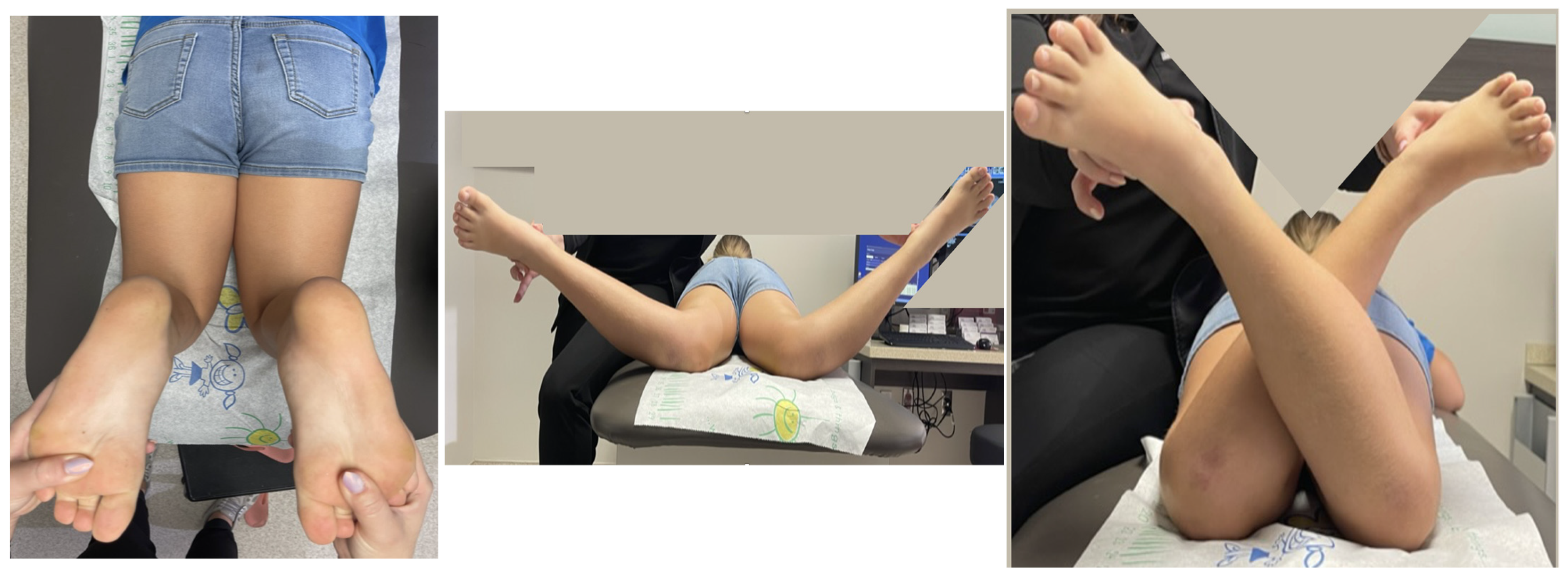
:1. Introduction
2. Materials and Methods
Surgical Technique
3. Results
4. Discussion
5. Conclusions
Author Contributions
Funding
Institutional Review Board Statement
Informed Consent Statement
Data Availability Statement
Acknowledgments
Conflicts of Interest
References
- Sawiris, Y.A.; Abo-Seif, S.; Aly, A.S. The Using of “Guided Growth” for Correction of Coronal Deformities around the Knee in Skeletally Immature Children (Systematic Review and Metaanalysis). Med. Clin. Rev. 2018, 4, 1–10. [Google Scholar] [CrossRef]
- Metaizeau, J.-D.; Denis, D.; Louis, D. New Femoral Derotation Technique Based on Guided Growth in Children. Orthop. Traumatol. Surg. Res. 2019, 105, 1175–1179. [Google Scholar] [CrossRef] [PubMed]
- Staheli, L.T.; Corbett, M.; Wyss, C.; King, H. Lower-Extremity Rotational Problems in Children. Normal Values to Guide Management. J. Bone Jt. Surg. Am. 1985, 67, 39–47. [Google Scholar] [CrossRef]
- Paley, D. Chapter 9: Rotation and Angulation-Rotation Deformities. In Principles of Deformity Correction; Springer: New York, NY, USA, 2002; pp. 235–268. [Google Scholar]
- Stevens, P.M. Guided Growth for Angular Correction: A Preliminary Series Using a Tension Band Plate. J. Pediatr. Orthop. 2007, 27, 253–259. [Google Scholar] [CrossRef] [PubMed]
- Stevens, P.M. The Role of Guided Growth as It Relates to Limb Lengthening. J. Child. Orthop. 2016, 10, 479–486. [Google Scholar] [CrossRef] [PubMed] [Green Version]
- Arami, A.; Bar-On, E.; Herman, A.; Velkes, S.; Heller, S. Guiding Femoral Rotational Growth in an Animal Model. J. Bone Jt. Surg. 2013, 95, 2022–2027. [Google Scholar] [CrossRef]
- Sevil-Kilimci, F.; Cobanoglu, M.; Ocal, M.K.; Korkmaz, D.; Cullu, E. Effects of Tibial Rotational–Guided Growth on the Geometries of Tibial Plateaus and Menisci in Rabbits. J. Pediatr. Orthop. 2019, 39, 289–294. [Google Scholar] [CrossRef]
- Lazarus, D.E.; Farnsworth, C.L.; Jeffords, M.E.; Marino, N.; Hallare, J.; Edmonds, E.W. Torsional Growth Modulation of Long Bones by Oblique Plating in a Rabbit Model. J. Pediatr. Orthop. 2018, 38, e97–e103. [Google Scholar] [CrossRef] [PubMed]
- Martel, G.; Holmes, L.; Sobrado, G.; Araujo, E.; Paley, D.; Praglia, F.; Arguello, G.; Arellano, E.; Flores, G. Rotational-Guided Growth. J. Limb. Lengthen. Reconstr. 2018, 4, 97–105. [Google Scholar] [CrossRef]


| Before Treatment | After Treatment | Amount of Correction (IR/ER/TFA) | ||||||||||||||||
|---|---|---|---|---|---|---|---|---|---|---|---|---|---|---|---|---|---|---|
| Hip Rotation Internal (IR) | Hip Rotation External (ER) | Thig Foot Axis (TFA) | Hip Rotation Internal | Hip Rotation External | Thig Foot Axis | |||||||||||||
| Patient | Age at Insertion (Years) | Diagnosis | Site | R | L | R | L | R | L | R | L | R | L | R | L | R | L | Time to Correct (Months) |
| 1 | 10.5 | Femur anteversion | Bilateral Femur | 60 | 65 | 20 | 20 | 40 | 40 | 50 | 45 | −20/30/- | −25/25/- | 15 | ||||
| 2 | 5.4 | Congenital pseudarthrosis of the tibia with external tibial torsion | Right Tibia | 30 | 19 | -/-/−11 | 18 | |||||||||||
| 3 | 7.7 | Femur anteversion | Right Tibia | −7 | 10 | -/-/17 | 11 | |||||||||||
| 3 | 8.6 | Internal tibial torsion | Right Femur | 60 | 40 | 50 | 60 | −10/20/- | 8 | |||||||||
| 4 | 15.7 | Congenital Femoral Deficiency with internal tibial torsion | Left Tibia | −15 | −10 | -/-/5 | ||||||||||||
| 5 | 2.6 | Femur anteversion | Bilateral Femur | 90 | 90 | 0 | 0 | 45 | 45 | 35 | 35 | −45/35/- | −45/35/- | 7 | ||||
Disclaimer/Publisher’s Note: The statements, opinions and data contained in all publications are solely those of the individual author(s) and contributor(s) and not of MDPI and/or the editor(s). MDPI and/or the editor(s) disclaim responsibility for any injury to people or property resulting from any ideas, methods, instructions or products referred to in the content. |
© 2022 by the authors. Licensee MDPI, Basel, Switzerland. This article is an open access article distributed under the terms and conditions of the Creative Commons Attribution (CC BY) license (https://creativecommons.org/licenses/by/4.0/).
Share and Cite
Paley, D.; Shannon, C. Rotational Guided Growth: A Preliminary Study of Its Use in Children. Children 2023, 10, 70. https://doi.org/10.3390/children10010070
Paley D, Shannon C. Rotational Guided Growth: A Preliminary Study of Its Use in Children. Children. 2023; 10(1):70. https://doi.org/10.3390/children10010070
Chicago/Turabian StylePaley, Dror, and Claire Shannon. 2023. "Rotational Guided Growth: A Preliminary Study of Its Use in Children" Children 10, no. 1: 70. https://doi.org/10.3390/children10010070