Article

A Stepwise Diagnosis Method for the Catalyst Loss Fault of the Cyclone Separator in FCC Units

1
College of Mechanical and Transportation Engineering, China University of Petroleum, Beijing 102249, China
2
Beijing Key Laboratory of Process Fluid Filtration and Separation, Beijing 102249, China
3
School of Intelligent Manufacturing, Wenzhou Polytechnic, Wenzhou 325035, China
4
Department of Chemical Engineering, China University of Petroleum (Beijing) at Karamay, Karamay 834000, China
*
Author to whom correspondence should be addressed.
Separations 2023, 10(1), 28; https://doi.org/10.3390/separations10010028
Submission received: 30 November 2022 / Revised: 25 December 2022 / Accepted: 30 December 2022 / Published: 3 January 2023

Abstract

:
The catalyst loss is one of the main faults that affects the long-term run of an FCC unit. Most catalyst loss faults, namely excessive emissions of the catalyst, are closely related to cyclone separators. The catalyst loss faults of the cyclone separator are usually caused by the abnormal changes in some aspects, such as the operational conditions and equipment performance and integrity, which directly affects the gas–solid separating operation and separation performance. This paper firstly summarized the various catalyst loss faults involving the cyclone separator in the FCC unit. Next, the characteristics of the catalyst loss faults and the main factors in the industrial operations were extracted and analyzed. Then, a stepwise diagnosis approach was proposed to determine the causes and location of catalyst loss faults of the cyclone separator. Finally, an industrial case was introduced in detail to prove the effectiveness of the method based on the sampled data from the commercial FCC unit. It is hopeful to provide a practical approach for the diagnosis and elimination of the catalyst loss fault in the FCC unit.

1. Introduction

Fluid catalytic cracking (FCC) is one of the main processes that converts heavy oil into valuable fuel products and petrochemical feedstock in the modern petroleum industry. The typical FCC process is shown in Figure 1, where the regenerator and disengager are arranged side by side. The catalyst participates in the oil–gas chemical reaction in the reactor and the coke-burning regeneration in the regenerator, meanwhile it circulates between the reactor and the regenerator without being discharged from the FCC units [1,2,3,4,5]. According to the processing capacity of the FCC unit, the catalyst circulating rate ranges from several hundred tons per hour to more than one thousand tons per hour [1]; hence, it is the demand that the gas–solid separator has a very high separation performance to recover the catalyst. The cyclone separator is usually preferred as the separation equipment for separating catalyst from oil gas or flue gas because of its low cost, simple structure without moving parts, high separation efficiency, and flexibility under operating conditions [6]. However, the catalyst loss faults often occur in the FCC unit, appearing as an excessive catalyst carryover to the main fractionator or a higher catalyst loss from the regenerator. The investigation also suggested that most of the catalyst loss faults are caused by the cyclone separator failure [7,8,9,10,11].
The catalyst loss is extremely adverse for the FCC unit. In terms of economic cost, it means increasing catalyst consumption and higher processing costs. From the point of view of the FCC unit operation, the catalyst loss will result in the reduction in the catalyst inventory, which further leads to the catalyst circulating rate not meeting the reaction requirements or the catalyst-to-oil ratio. In addition, a high catalyst loss will also result in a reduction in the amount of 0~40 μm particles in the equilibrium catalyst, which leads to the deterioration of the fluidization properties [12,13]. Moreover, the catalyst loss is harmful to the operation of downstream equipment, for example, escaped fines will enter the flue gas turbines to cause the particle deposition on the blades and the erosion of the blades [14,15,16] or will enter the main fractionator to cause blockage in the pipeline and to cause the erosion of the slurry pump.
The cyclone separator is a key equipment for the long-term running of FCC units and its separation operation between catalyst and oil gas or flue gas is critical to determine the catalyst loss. On the one hand, the catalyst particles belong to Geldart Group A particles, containing fractionally less than 10 μm, which requires the cyclone separators to be highly efficient to meet the specified emission standard. On the other hand, the operation conditions of the cyclone separator are relatively harsh and variable, such as high temperature and high pressure and high inlet particle concentration, which requires that the gas–solid separation has a high reliability. The FCC cyclone separator system is mainly composed of several groups of cyclone separators in series and in parallel, diplegs, trickle valves, cyclone hangers, and dipleg bracing rods. These components will inevitably have various failures during the long-term running, or the performance of these components are influenced by the abnormal process parameters and poor catalyst properties, resulting in the efficiency of the cyclone separator gradually deteriorating [17,18,19,20].
The catalyst loss is a complex engineering problem and related to many factors such as equipment performance and catalyst particle properties. Current references mainly focus on the qualitative analysis of FCC catalyst loss [7,8,10,19] or the effect of one factor on catalyst loss [17,21,22]. For example, Koebel [10] thought the serious catalyst losses were related to catalyst bed level, sever cyclone failure, and operational upsets and further estimated the calculation equation of the bed level. Shaw [13] discussed the effect of trickle valve operation on catalyst loss. Andreas [21] simulated the effect of catalyst attrition on catalyst loss in a circulating fluidized bed (CFB) process. Gas leakage into cyclones [22] and blocked dipleg by deposits [19] also lead to the increase in catalyst loss rate. In the commercial operation, the diagnosis of FCC catalyst loss fault mainly depends on the data obtained from the unit operation and the previously accumulated experience. Thus, it can be seen that studies about the catalyst loss of the cyclone separator are still lacking and more industrial data are needed to support some viewpoints. It is also necessary to systematically analyze the catalyst loss fault of the cyclone separator and establish a practical diagnosis method.
In this paper, various catalyst loss faults of the cyclone separator in commercial FCC units are firstly summarized. Then, the main parameters related to the catalyst loss of the cyclone separator are extracted. Finally, the paper focuses on proposing a stepwise diagnosis approach for catalyst loss faults of the cyclone separator. The results will be helpful in providing a guideline for the diagnosis of the catalyst loss fault in the FCC unit.

2. Classification of Catalyst Loss

The FCC catalyst loss can be divided into natural loss and non-natural loss. Natural loss refers to the catalyst loss caused by the catalyst fines escaping from the cyclone separator under the conditions of normal operation. The catalyst fines leave the regenerator with flue gas or leave the reactor with oil vapor due to the low separation capacity of cyclone separators to fines. A 2.0 Mt/a FCC unit (see Figure 1) was selected for the catalyst sampling under normal operation conditions. The sampling locations are shown in Figure 1. The regenerated catalyst and the spent catalyst are sampled from the regenerated catalyst standpipe (1#) and the spent catalyst standpipe (2#), respectively. The catalyst in the dilute zone of the regenerator is sampled at the location of 3#. The catalyst in the third stage separator (TSS) inlet pipeline, the TSS outlet pipeline, and the TSS hopper are sampled at locations 4#, 5#, and 6#, respectively.
The particle size distributions (PSD) of the catalyst samples inside the reactor and regenerator are shown in Figure 2a and the PSDs of the catalyst samples flowing out of the regenerator are shown in Figure 2b. The characteristic sizes of the catalysts are listed in Table 1. Both PSDs of the equilibrium catalyst and the spent catalyst in Figure 2a present a normal bell curve in the logarithmic coordinates. The particle size of the equilibrium catalyst is mainly in the range of 20~160 μm and the median particle size is 67.82 μm. The corresponding characteristic sizes of the spent catalyst and the fresh catalyst are close, compared with the equilibrium catalyst. The particle size of the catalyst sample in the dilute zone of the regenerator is mainly in the range of 20~100 μm and the median particle size is 38.24 μm.
PSD is an important indicator to describe the fluidization properties of the catalyst, the performance of the cyclone separator, and the attrition resistance of the catalyst. In the sample analysis of the equilibrium catalyst, a content of less than 40 μm fines is usually about 16.3% within the normal range. The obvious decrease in the content of fines in the equilibrium catalyst indicates the reduction in the separation efficiency of the cyclone separator, which can be further confirmed from the PSD of the catalyst collected from the downstream equipment or pipelines.
The PSDs of the lost catalyst in Figure 2b show an irregular distribution curve. The lost catalyst is the enrichment of fines in the equilibrium catalyst, which contains a lot of information about the process parameters, the separation performance of the cyclone separator, equipment integrity, and the catalyst attrition source. The particle size range of the lost catalyst in the flue gas of the TSS inlet is mainly in the range of less than 40 μm and the median particle size is about 19.07 μm, as shown in Figure 2b and Table 1. Therefore, the natural loss of catalyst mainly depends on the content of particles less than 40 μm in the equilibrium catalyst and the spent catalyst and the separation capacity of the cyclone separator to catalyst fines. In addition, the PSD of the catalyst in the TSS inlet pipeline in Figure 2b is of bimodal distribution, which can be attributed to the catalyst attrition to produce a peak at dp = 1.5 μm.
The non-natural loss belongs to the catalyst fault loss, which means the catalyst loss rate exceeds the natural loss rate. According to the investigation, the catalyst loss faults of the cyclone separator are closely related to FCC operating conditions (such as the gas flow rate, solids’ loading, operating pressure, catalyst properties, etc.) and equipment performance and integrity, as shown in Figure 3. For example, the pressure fluctuation of the fluidized bed will disturb the dipleg discharge and excessive negative pressure difference in the dipleg will lead to the accumulation of the catalyst in the dipleg and the cyclone separator to form “solid flooding”. The catalyst particle properties causing the catalyst loss usually originate from the catalyst qualities that do not meet the specified standard, such as excessive fine content, high attrition index, and heavy metal content, etc. The mechanical damage or failure of the cyclone, which includes wear or holes at the wall and trickle valve, fracture of dipleg, blockage of dipleg, etc., is extremely adverse for the recovery of the catalyst. All these factors will eventually affect the separation operation of the cyclone separator, leading to gas–solid separation efficiency decreasing and excessive catalyst emissions.

3. Diagnosis Method of Catalyst Loss Fault

3.1. Characteristics of Catalyst Loss Fault

According to the extent of the catalyst loss, the catalyst loss fault of the cyclone separator in the FCC unit can be divided into three types of working status, i.e., natural catalyst loss, fault catalyst loss, and shutdown catalyst loss, as shown in Figure 4. The FCC unit requires that the working status of the cyclone separator is in the region of the natural catalyst loss. If the operation of the cyclone separator is in the fault catalyst loss zone, it is possible to return to the natural catalyst loss region by adjusting the corresponding parameters and troubleshooting. For example, the inlet concentration of particles in the cyclone separator slightly increases due to the excessive main air or the large bubbles in the fluidized bed interfering with the trickle valve discharge. These faults can be eliminated by adjusting the corresponding process parameters. Once the mechanical damage is involved, it is difficult to eliminate the catalyst loss fault. Sometimes, in order to maintain the long-term run of the FCC unit, it is necessary to achieve sustainable operations under the conditions of an acceptable catalyst loss until the next scheduled shutdown. However, when the mechanical problems of the cyclone separator are serious, a large amount of catalyst runs off continually and it will be difficult to replenish the catalyst in time to maintain the catalyst inventory such as the dipleg blockage or fracture. It means the working condition of the cyclone separator has been in the region of a shutdown and the FCC unit faces an unscheduled shutdown.
The characteristics of the catalyst loss fault of the cyclone separator in the FCC unit are as follows.
  • Diversity and multifactor. Many process parameters and equipment parameters are related to catalyst loss in the cyclone separators, which leads to various forms of catalyst loss. The extent of catalyst loss fault is also different. Catalyst loss is caused by one or multiple factors (usually a combined result of multiple factors). The operation of each unit in the FCC unit is interrelated with catalyst circulation and the failure of one unit will directly affect the operation of the next unit or other units. For example, the overload operation of the FCC unit will lead to the increase in the inlet velocity to deviate from the optimal design range. Further, the catalyst attrition and the erosion of refractory lining will increase.
  • Delay and burst. The cyclone separator is subject to the erosion and wear by the gas–solid two-phase flow, which leads to the aging of the equipment and the degradation of the separation function. The catalyst loss shows a gradual increase, which is characterized by time delay or time varying. For example, the refractory lining of the cyclone separator is worn for a long time until the wall is perforated. Sometimes, the catalyst loss fault occurs suddenly, e.g., when the dipleg of the cyclone separator is blocked or fractured.
  • Uncertainty. The forms of catalyst loss are often different, even for two FCC units with the same configuration. The fault symptom may be from different causes of a variety of faults or one fault shows a variety of symptoms; hence, there exists the uncertainty of fault symptoms and causes. The mechanisms of most catalyst losses are not clear and there is a lack of measurable parameters to accurately diagnose the fault causes.

3.2. Stepwise Diagnosis Method for Catalyst Loss Fault

3.2.1. Data Collection

Once the catalyst loss fault of the cyclone separator occurs, the first work we need to perform is to collect the relevant data of the FCC unit operation and then compare these data with the historical data under normal operation conditions or the design data. The most common parameters for monitoring the catalyst loss are catalyst loss rate, properties of catalyst, catalyst inventory, and the pressure drop of the cyclone separator. At present, the diagnosis data mainly come from two sources. One is the parameters measured online, including catalyst circulation rate, catalyst loss rate, particle concentration of the outlet pipeline, inlet velocity, pressure drop, outlet pressure and pressure fluctuation, and operating temperature. The other is the parameters measured offline, mainly including the particle size distribution (particle number fraction or particle volume or mass fraction), particle bulk density, microscopic morphology, and content of some chemical elements in the sampled catalyst.

3.2.2. Fault Factors Analysis

4.
Catalyst loss rate.
The catalyst loss rate is an important parameter during the diagnostic process of the fault. The increase in the catalyst loss rate is closely related to the separation efficiency of the cyclone separator. Figure 5 presents the time-varying characteristics of the catalyst loss rate. Under normal operation conditions, the catalyst loss rate keeps at the normal line, about 0.4 kg/t feed. A gradual increase in the catalyst loss rate with time is usually related to the equipment operating parameters, catalyst attrition, or early wall erosion of the cyclone separator. Of course, the catalyst loss rate also increases steadily due to the loss of fines in the fresh catalyst during the initial stage of the FCC unit start-up. If the catalyst loss is caused by operation parameters, it can be eliminated by some measures and can return to the normal operation status, while a sudden increase in the catalyst loss rate means a sudden degradation of the separation function of the cyclone separator, which is usually caused by mechanical failures such as wear hole of the wall, dipleg blockage, fracture, or flooding.
The key operating parameters that influence the catalyst loss rate are the main air or the fluidization velocity. With the increase in the fluidization velocity, the TDH (transport disengaging height) will rise [23], meanwhile the inlet gas velocity and the particle concentration of the cyclone separator will exceed the design rating [24], leading to the increase in the catalyst loss rate.
Wear is the main reason for the mechanical failure of the cyclone separator. The initial wear will make the wall rougher, will affect the intensity of the swirling flow, and will further cause the catalyst loss rate to gradually increase. Once the holes appear due to wear, the gas in-leakage may happen. The in-leaked gas will entrain the collected catalyst particles in the cyclone separator and the catalyst in the dilute zone to escape from the gas outlet tube of the cyclone separator. Even a 10 mm hole can increase the catalyst losses several-fold. As a result, the median particle size of the equilibrium catalyst will increase. The high-velocity gas entrains the catalyst pass through the hole and therefore further increases the hole size and intensifies the catalyst loss [7]. The PSD of the lost catalyst mainly depends on the size of the hole and the position of the holes. For instance, when the hole is located on the cone of the second-stage cyclone separator, the PSD shows the normal peak at around 20 μm and a second peak at about 30 μm [8].
5.
Pressure drop.
Pressure drop is an important and measurable performance parameter of the cyclone separator, which usually varies with the inlet gas velocity and the inlet particle concentration. In addition, the pressure drop also changes with the occurrence of the catalyst loss fault. Figure 6 illustrates the time-varying characteristics of the pressure drop of the cyclone separator. There are usually four changing trends based on the industrial observation.
For line 1 in Figure 6, the pressure drop increases gradually, which is usually attributed to the increase in the processing load. At this time, the catalyst in the dipleg will back up a higher elevation to provide enough static head to force the catalyst to discharge out of the dipleg. With the increase in the catalyst column height in the dipleg, the flooding will occur and the swirling flow in the bottom of the cyclone will re-entrain the catalyst and dramatically reduce the collection efficiency of the cyclones.
For line 2, a gradual decrease is usually related to the decrease in the processing load under the normal working status. If the processing load remains unchanged, it means the gas in-leakage may occur. From the PSD, the fines in the lost catalyst decrease in the magnitude and the normal peak shifts toward a larger particle size. It should be noted that the fluctuation of the pressure drop usually occurs together with the decrease in the pressure drop when gas in-leakage happens, as shown in Line 3 of Figure 6. The reason is that gas in-leakage results in the unstable discharge at the trickle valve or unstable swirling flow in the cyclone separator [22,25]. A very low pressure drop in line 4 of Figure 6 means that there is no swirling flow in the cyclone separator such as the dipleg fracture or solid flooding.
6.
Catalyst particles.
The separation performance of the cyclone separator in the regenerator and the reactor can be monitored by the PSD analysis of the lost catalyst. In general, the PSD of the lost catalyst usually has a unimodal distribution under normal operating conditions of cyclone separators. With the gradual loss of fines, the equilibrium catalyst in the FCC unit gradually coarsens and the peak value or median diameter gradually increases. When a serious catalyst loss fault occurs, the PSD of the lost catalyst usually presents a multimodal distribution associated with different fault sources. The new peak originates from another type of lost catalyst, which is superimposed on the unimodal distribution of the natural loss catalyst.
The catalyst attrition has an important effect on the PSD of the lost catalyst, which has been discussed in the previous literature [21,26,27,28]. When the catalyst particles are subjected to a low velocity collision, the main mechanism of attrition is surface abrasion of catalyst particles, which leads to the production of 1~2 μm fines, as shown in the left SEM photo of Figure 7. That is why an abnormal peak at around 1~2 μm exists in the PSD of the catalyst from the TSS outlet in Figure 2b. Under the higher gas velocity conditions, such as that in the cyclone separator near the feed nozzle, the stripping steam nozzle, or the outlet of nozzle from air distributor, the particles usually break into two or more fragments, leading to the production of larger particles about 20 μm; see the right SEM photo of Figure 7. Moreover, when catalyst particles are mixed with the catalyst at a significantly higher temperature, thermal shock may occur, leading to the fracture of larger particles [29]. Generally, the more the proportion of the abnormally lost catalysts is, the higher the new peak value in the PSD becomes.

3.2.3. Diagnosis Method for Catalyst Loss Fault

The fault diagnosis has developed as an active research topic in recent years. Extensive studies of different fault diagnosis methods can be found in the literature [30,31,32,33,34,35]. The methods can be grouped into three categories: analytical model-based, knowledge-based, and data-based diagnosis methods. Due to the complexity of the catalyst loss faults of cyclone separators in FCC units, it is difficult to establish an accurate fault diagnosis model at present. However, some of the factors, such as catalyst loss rate, the pressure drop of the cyclone separator, and the PSD of the lost catalyst, are measurable, which reflects the causes of catalyst loss and can be used for fault diagnosis. Therefore, it is feasible to establish a relationship model between the related parameters and the catalyst loss fault based on the online data, offline data, and historical data. Figure 8 illustrates the diagnosis guidelines of the catalyst loss faults of the cyclone separator, which made full use of the operation parameters of the FCC unit, the pressure drop of the cyclone separator, the properties of the lost catalyst and the equilibrium catalyst, and other relevant data for troubleshooting the catalyst loss step by step.

3.2.4. A Case of Catalyst Loss Fault in a Commercial FCC Unit

The catalyst loss rate suddenly increased from about 3.0 tons per day to more than 12.8 tons per day for a 2.0 Mt/a FCC unit (as shown in Figure 1), which had been continuously operating for one year. In this FCC unit, the reactor and the regenerator were arranged side by side and there were seven parallel sets of two-stage cyclone separators in the regenerator.
A systematic step-by-step method was followed to identify the root cause of the catalyst loss fault. Under the normal operation status, the circulating rate of catalyst particles was about 1530 tons per hour, the pressure drop of the cyclone separator in the regenerator maintained at about 7.9~8.2 kPa, and its fluctuation range was within 0.2 kPa. The catalyst concentration in the regenerator outlet pipeline was lower than 0.5 g/m3 and in the slurry of the reactor side it was lower than 3.7 g/L.
The preliminary investigation suggested that the catalyst concentration in the slurry was still normal, which indicated that the cyclone separator in the reactor side was in normal operation status. Furthermore, the causes of the operation parameters, catalyst qualities, and catalyst attrition were eliminated. Hence, it can be speculated that the catalyst loss is from the regenerator side.
In order to further identify the cause of the fault, the isokinetic sampling was carried out in the TSS inlet pipeline, the TSS outlet pipeline, and the TSS hopper, respectively. The results showed that the catalyst concentration in the TSS inlet pipeline exceeded 1270 mg/m3, indicating the degradation of the separation performance of the cyclone separators in the regenerator. Figure 9 presents the PSDs of the sampled catalyst from TSS under the fault operation status compared with that under normal operation status. From Figure 9a, the PSD of the catalyst particles in the flue gas inlet of TSS presented a multimodal distribution under the fault conditions; the 30 μm peak value and the proportion in the PSD were relatively high. The peak at dp = 30 μm indicated that larger particles directly escaped from the cyclones and were superimposed on the unimodal distribution of the natural loss catalyst. The PSDs of the collected catalyst in the hopper (Figure 9b) and in the TSS outlet (Figure 9c) further confirmed the abnormal existence of the large particles.
Furthermore, the pressure drop of the cyclone separators in the regenerator was observed to decrease to 7.5 kPa (as shown in Figure 10), which indicated that the swirling flow in the cyclone separator was disturbed and its intensity was attenuated. The fluctuation range of the pressure drop increased to 0.75 kPa from 0.2 kPa, which indicated that the swirling flow or the particles’ discharge was unstable. Based on the analysis, it can be speculated that gas in-leakage may occur, which may originate from the big holes at the cyclone wall or dipleg fracture.
During the shutdown inspection of the FCC unit, it was observed that the two diplegs of the second-stage cyclone separators were broken at the welding seam, as shown in Figure 11. This is a metal fatigue fracture caused by the induced mechanical vibration. As a result, the catalyst in the dilute space of the regenerator was entrained by flue gas directly into the dipleg from the crack. Meanwhile, the in-leaked gas disturbed the collected catalyst transporting downward. The upward gas carried the catalyst particles directly into the inner swirling flow of the cyclone separator to escape from the gas outlet tube. That is why the particles larger than 30 μm increased significantly in the flue gas at the outlet of the regenerator or TSS inlet, as shown in Figure 9a.

4. Conclusions

The catalyst loss of the cyclone separator is one of the main faults that affect the long-term run of an FCC unit. The purpose of this study is to provide a deeper understanding of the catalyst loss problem based on the industrial observation and measurable data. An effort is devoted to establish a stepwise and logic flow diagram to help quickly identify the cause of the catalyst loss. The following conclusions can be drawn from this work.
7.
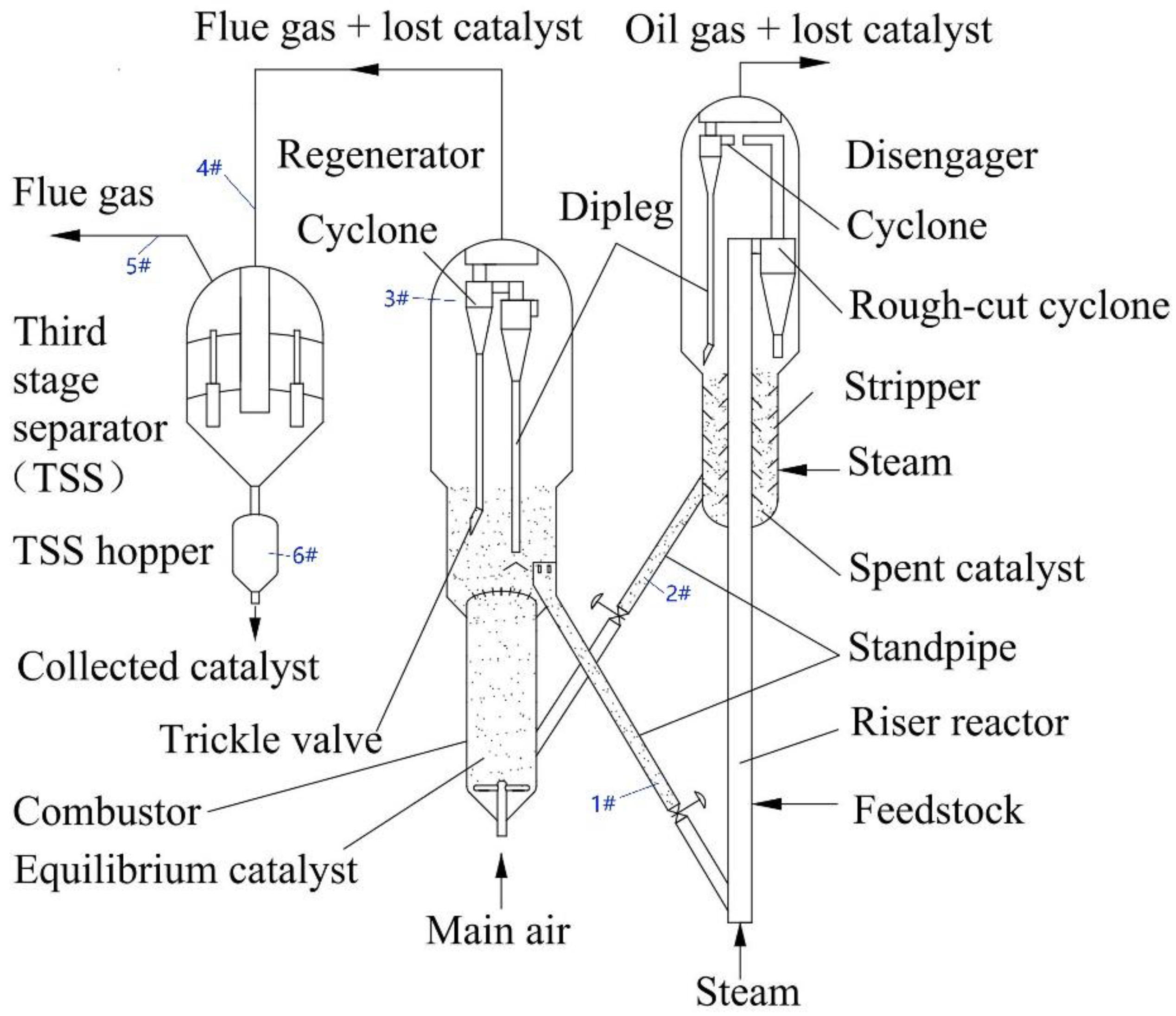
The FCC catalyst loss can be divided into the natural loss and the non-natural loss. Under normal operations, the catalyst PSD by the natural loss was presented from the different sampling positions in an industrial 2.0 Mt/a FCC unit, which suggested that the regenerated catalyst (equilibrium catalyst), the spent catalyst, and the fresh catalyst were the normal bell curves in the logarithmic coordinates. The characteristic sizes of the spent catalyst and the fresh catalyst were close to that of the equilibrium catalyst. The PSDs of the lost catalyst showed an irregular distribution curve.
8.
According to the industrial investigation, the catalyst loss faults of the cyclone separator were closely related to FCC operating conditions (such as the gas flow rate, solids’ loading, operating pressure, catalyst properties, etc.) and equipment performance and integrity. For the catalyst loss fault of the cyclone separator, there are three main characteristics, i.e., diversity and multifactor, delay and burst, and uncertainty. The catalyst loss rate, pressure drop, and PSD of catalyst particles are three key and measurable parameters for the identification of the catalyst loss fault of the cyclone separator.
9.
Given the complexity of the catalyst loss fault, a stepwise diagnosis method based on the measurable data was proposed and the detailed flow diagnosis diagram was introduced. A commercial case suggested the stepwise diagnosis method is effective and helpful, which can be applied in the commercial operations of the FCC unit.

Author Contributions

Conceptualization, J.S. and Y.W.; investigation, D.W.; Y.H., P.L. and W.P.; writing—original draft preparation, J.S.; writing—review and editing, Y.W.; supervision, Y.W.; funding acquisition, J.S. All authors have read and agreed to the published version of the manuscript.

Funding

The research was funded by the National Natural Science Foundation of China (22178382).

Institutional Review Board Statement

Not applicable.

Informed Consent Statement

Not applicable.

Data Availability Statement

All data generated or analyzed during this study are included in the published article.

Conflicts of Interest

The authors declare no conflict of interest.

References

  1. Sadeghbeigi, R. Fluid Catalytic Cracking Handbook, 2nd ed.; Gulf Professional Publishing Company: Houston, TX, USA, 2000. [Google Scholar]
  2. Chen, Y.-M. Recent advances in FCC technology. Powder Technol. 2006, 163, 2–8. [Google Scholar] [CrossRef]
  3. Bollas, G.M.; Vasalos, I.A.; Lappas, A.A.; Iatridis, D.K.; Voutetakis, S.S.; Papadopoulou, S.A. Integrated FCC riser—Regenerator dynamics studied in a fluid catalytic cracking pilot plant. Chem. Eng. Sci. 2007, 62, 1887–1904. [Google Scholar] [CrossRef] [Green Version]
  4. Jarullah, A.T.; Awad, N.A.; Mujtaba, I.M. Optimal design and operation of an industrial fluidized catalytic cracking reactor. Fuel 2017, 206, 657–674. [Google Scholar] [CrossRef] [Green Version]
  5. John, Y.M.; Mustafa, M.A.; Patel, R.; Mujtaba, I.M. Parameter estimation of a six-lump kinetic model of an industrial fluid catalytic cracking unit. Fuel 2019, 235, 1436–1454. [Google Scholar] [CrossRef] [Green Version]
  6. Hoffmann, A.C.; Stein, L.E. Gas Cyclones and Swirl Tubes: Principles, Design and Operation, 2nd ed.; Springer: Berlin/Heidelberg, Germany, 2008. [Google Scholar]
  7. Niccum, P.K. 20 questions: Identify probable causes for high catalyst loss. Hydrocarb. Process. 2010, 9, 29–38. [Google Scholar]
  8. Fletcher, R. Stepwise method determines source of FCC catalyst losses. Oil Gas J. 1995, 93, 79–81. [Google Scholar]
  9. Saidulu, G.; Palappan, K.G.; Bhuyan, M.K.; Satheesh, V.K.; Bhattacharyya, D.; Rajagopal, S. Optimizing conditions, modifying design improve FCC regenerator. Oil Gas J. 2010, 108, 123–129. [Google Scholar]
  10. Koebel, J.; Davison, G. Troubleshooting FCC Catalyst Losses. Refin. Oper. 2011, 2, 1–4. [Google Scholar]
  11. Hunt, D.A.; Krishnaiah, G. Optimizing FCC regenerator can minimize catalyst losses. Oil Gas J. 2001, 99, 56–58, 60–61. [Google Scholar]
  12. McLean, J.B. FCC catalyst properties can affect cyclone erosion. Oil Gas J. 2000, 98, 33–36. [Google Scholar]
  13. Shaw, D.F.; Walter, R.E. How FCCU trickle valves affect catalyst losses. Hydrocarb. Process. 2007, 171, 75–84. [Google Scholar]
  14. Wang, J.; Lin, Y.; Xu, W.; Li, Q.; Dandekar, A. Effects of blade roughness on particle deposition in flue gas turbines. Powder Technol. 2019, 353, 426–432. [Google Scholar]
  15. Xu, W.; Zhu, K.; Wang, J.; Lin, Y.; Li, Q. Modeling and numerical analysis of the effect of blade roughness on particle deposition in a flue gas turbine. Powder Technol. 2019, 347, 59–65. [Google Scholar]
  16. Pan, J.; Wang, J.; Chen, S.; Zhang, X.; Liu, S. Numerical study of inlet Reynolds number in fine particles deposition processes in a flue gas turbine. Powder Technol. 2018, 339, 506–520. [Google Scholar] [CrossRef]
  17. Peng, W.; Wei, Y.; Liu, Y.; Han, S.; Bao, B. Effect of flow patterns in the recirculation catalyst standpipe on the performance of FCC high-efficiency regenerator. Chem. Eng. Sci. 2022, 248, 117145. [Google Scholar] [CrossRef]
  18. Zheng, M.; Chen, G.; Han, J. Failure analysis on two austenitic stainless steels applied in cyclone separators of catalytic cracking unit. Eng. Fail. Anal. 2011, 18, 88–96. [Google Scholar] [CrossRef]
  19. McPherson, L.J. Causes of FCC reactor coke deposits identified. Oil Gas J. 1984, 82, 139–143. [Google Scholar]
  20. Koten, H. Recent Research in Engineering Sciences; Livre de Lyon: Lyon, France, 2021; ISBN 978-2-38236-155-9. [Google Scholar]
  21. Thon, A.; Püttmann, A.; Hartge, E.-U.; Heinrich, S.; Werther, J.; Patience, G.S.; Bockrath, R.E. Simulation of catalyst loss from an industrial fluidized bed reactor on the basis of labscale attrition tests. Powder Technol. 2011, 214, 21–30. [Google Scholar] [CrossRef]
  22. Wang, D.; Sun, L.; Wang, J.; Liu, J.; Wei, Y.; Song, J. Experimental study of the dynamic characteristics of a cyclone by hot wire/film anemometry: Effects of gas leakage. Sep. Purif. Technol. 2020, 251, 117365. [Google Scholar] [CrossRef]
  23. Cahyadi, A.; Neumayer, A.H.; Hrenya, C.M.; Cocco, R.A.; Chew, J.W. Comparative study of Transport Disengaging Height (TDH) correlations in gas–solid fluidization. Powder Technol. 2015, 275, 220–238. [Google Scholar] [CrossRef]
  24. Whitcombe, J.; Cropp, R.; Braddock, R.; Agranovski, I. Application of sensitivity analysis to oil refinery emissions. Reliab. Eng. Syst. Saf. 2003, 79, 219–224. [Google Scholar] [CrossRef]
  25. Karri, S.; Knowlton, T.M. Effect of Aeration on the Operation of cyclone diplegs fitted with trickle valves. Ind. Eng. Chem. Res. 2004, 43, 5783–5789. [Google Scholar] [CrossRef]
  26. Bayham, S.C.; Breault, R.; Monazam, E. Particulate solid attrition in CFB systems–An assessment for emerging technologies. Powder Technol. 2016, 302, 42–62. [Google Scholar] [CrossRef] [Green Version]
  27. Kukade, S.; Kumar, P.; Rao, P.V.; Choudary, N.V. Comparative study of attrition measurements of commercial FCC catalysts by ASTM fluidized bed and jet cup test methods. Powder Technol. 2016, 301, 472–477. [Google Scholar] [CrossRef]
  28. Fulchini, F.; Ghadiri, M.; Borissova, A.; Amblard, B.; Bertholin, S.; Cloupet, A.; Yazdanpanah, M. Development of a methodology for predicting particle attrition in a cyclone by CFD-DEM. Powder Technol. 2019, 357, 21–32. [Google Scholar] [CrossRef]
  29. Whitcombe, J.M.; Agranovski, I.E.; Braddock, R.D. Attrition due to mixing of hot and cold FCC catalyst particles. Powder Technol. 2003, 137, 120–130. [Google Scholar] [CrossRef]
  30. Venkatasubramanian, V.; Rengaswamy, R.; Yin, K.; Kavuri, S.N. A review of process fault detection and diagnosis. Part I. Quantitative model-based methods. Comput. Chem. Eng. 2003, 27, 293–311. [Google Scholar] [CrossRef]
  31. Sotomayor, O.A.; Odloak, D. Observer-based fault diagnosis in chemical plants. Chem. Eng. J. 2005, 112, 93–108. [Google Scholar] [CrossRef]
  32. Agudelo, C.; Anglada, F.M.; Cucarella, E.Q.; Moreno, E.G. Integration of techniques for early fault detection and diagnosis for improving process safety: Application to a Fluid Catalytic Cracking refinery process. J. Loss Prev. Process Ind. 2013, 26, 660–665. [Google Scholar] [CrossRef]
  33. Tian, W.; Wang, S.; Sun, S.; Li, C.; Lin, Y. Intelligent prediction and early warning of abnormal conditions for fluid catalytic cracking process. Chem. Eng. Res. Des. 2022, 181, 304–320. [Google Scholar] [CrossRef]
  34. Bi, X.; Qin, R.; Wu, D.; Zheng, S.; Zhao, J. One step forward for smart chemical process fault detection and diagnosis. Comput. Chem. Eng. 2022, 164, 107884. [Google Scholar] [CrossRef]
  35. Arunthavanathan, R.; Khan, F.; Ahmed, S.; Imtiaz, S. An analysis of process fault diagnosis methods from safety perspectives. Comput. Chem. Eng. 2021, 145, 107197. [Google Scholar] [CrossRef]
Figure 1. A schematic diagram of the FCC process.
Separations 10 00028 g001
Figure 2. PSD of the catalyst samples (a) in the reactor and regenerator and (b) collected in the downstream of the regenerator.
Separations 10 00028 g002
Figure 3. Factors of catalyst loss in the cyclone separator.
Separations 10 00028 g003
Figure 4. Classification of catalyst loss fault.
Separations 10 00028 g004
Figure 5. Time-varying characteristics of catalyst loss rate.
Separations 10 00028 g005
Figure 6. Time-varying characteristics of pressure drop of the cyclone separator.
Separations 10 00028 g006
Figure 7. SEM of lost catalyst in FCC unit caused by surface abrasion (left) and high-velocity stream striking (right).
Separations 10 00028 g007
Figure 8. A stepwise diagnosis method for catalyst loss fault.
Separations 10 00028 g008
Figure 9. PSD of catalyst particles (a) in the TSS inlet pipeline, (b) in the TSS hopper, and (c) in the TSS outlet pipeline.
Separations 10 00028 g009aSeparations 10 00028 g009b
Figure 10. Pressure drop fluctuation of the cyclone separator.
Separations 10 00028 g010
Figure 11. The dipleg fracture in the commercial FCC unit.
Separations 10 00028 g011
Table 1. Characteristic sizes of catalyst samples.
NumberSampled CatalystMedian (μm)Mean (μm)Mode (μm)
1Regenerated catalyst (equilibrium catalyst)67.8272.1872.94
2Spent catalyst68.0372.2980.07
3Fresh catalyst71.0477.5372.94
4Catalyst in dilute zone of the regenerator38.2440.6937.97
5Catalyst in TSS inlet19.0717.5123.81
6Catalyst in TSS outlet1.6892.161.919
7Collected catalyst in TSS hopper14.9214.7121.69
Note: (1) median is read from the cumulative distribution as the 50% size; (2) mean is the arithmetic mean value of particle size; (3) mode is the most frequently occurring size.
Disclaimer/Publisher’s Note: The statements, opinions and data contained in all publications are solely those of the individual author(s) and contributor(s) and not of MDPI and/or the editor(s). MDPI and/or the editor(s) disclaim responsibility for any injury to people or property resulting from any ideas, methods, instructions or products referred to in the content.

