Article

Theory of Gas Purification by Liquid Absorber in Small Rotating Channels with Application to the Patented Rotational Absorber Device

by
J. J. H. Brouwers
Romico Hold VBA., 6226 GV Maastricht, The Netherlands
Separations 2024, 11(12), 338; https://doi.org/10.3390/separations11120338
Submission received: 21 October 2024 / Revised: 12 November 2024 / Accepted: 20 November 2024 / Published: 26 November 2024

Abstract

:
A new design for absorbing vapour-phase impurities from gases is presented. It consists of small channels packed in a rotating vertical cylinder. Gas flows through the channels adjacent to a thin film of absorber liquid. The liquid film is pressed to the radially outward side of each channel by the centrifugal force and flows downwards by gravity. Formulae are presented which describe the concentration distributions of gaseous impurities subject to absorption in gas and liquid. Results include expressions for laminar and turbulent diffusion coefficients to be used in mass balance equations. The role of rotation is quantified including the effect on wavy motion and enhanced diffusion in the liquid layer. Application in design is indicated for the case of separation of the greenhouse gas C O 2 from flue gases of fossil fuel combustion processes. At other equal dimensions, the height of the Rotational Absorber Device is calculated to be 25 times shorter than the enormous heights of conventional tray and packed columns.

1. Introduction

Removing gas phase impurities from gases by absorption is widely used in engineering applications. The gas is brought into contact with a liquid with the aim of allowing certain gaseous components of the gas to diffuse to the absorbing liquid. Absorption processes are used to purify gas streams or to limit emissions [1]. Examples are the removal of H 2 S and C O 2 from contaminated natural gas using Amines, contacting Glycol with gasses to absorb water vapour, and removing S O 2 from combustion gasses using salty water. Commonly applied techniques are [1] (i) spraying the absorbing liquid in the form of droplets in the gas flowing in a so-called spray chamber; (ii) dividing the gas into small bubbles moving through a continuous liquid phase in so-called tray columns; and (iii) letting the liquid flow in thin films over solid particles packed in a column through which the gas flows, the so-called packed column. Gas purification by spray chambers is economical in bulk applications where demands for degrees of purification are limited. Tray and packed columns are seen in cases where high degrees of purification are desired. Installations used in industrial processes can be as high as 10 m and more.
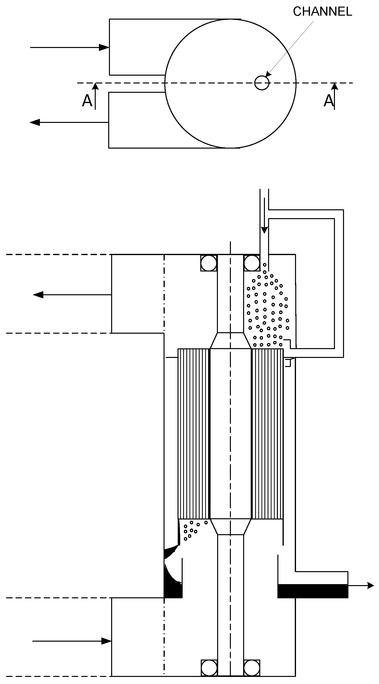
A new technology is provided by the Rotational Absorber Device patented in 2021 [2]. The core of the device is a rotating cylinder which consists of a multitude of channels whose diameter can be as small as one millimetre [2,3]. The channels are bundled in a cylindrical body and rotate as a solid body around the vertical central symmetry axis. Gas can be fed at the top or at the bottom with the outlet on the other side. Absorber liquid is injected at the top of the channels and driven by gravity leaves at the bottom. The liquid serves as a means to absorb gas phase impurities present in the gas, thus cleaning the gas. Because of rotation, the liquid flows as a thin film a few tens of micrometres in size downwards along the radially outward wall of the channel. Whilst the liquid flows always downwards, the gas can flow upwards, in which case we have a counter-current situation, which is shown in Figure 1, or downwards, in which case we have a co-current situation. Using the Rotational Absorber Device, high degrees of separation can be achieved, while the height of the installation is up to ten times smaller than that of the tray and packed columns with similar performance.
Different from the existing processes is the application of the new concept of thin vertically oriented channels in which gas and liquid streams are separated as a result of the rotation of the cylindrical body in which the channels are positioned. The aim of this article is to present formulae which describe the absorption process in these channels. In Section 2, the formulae for the changes in concentrations of gas phase impurities in gas and liquid due to absorption are presented. In these formulae, mass transfer coefficients are used, which are derived from general the diffusion theory in Section 3. Explicit expressions for the mass transfer coefficients as a function of design parameters are developed in Section 4. Section 5 treats wave-induced transfer in the liquid layer while Section 6 analyses the role of rotation. Application in design is discussed in Section 7 for the case of separation of the greenhouse gas C O 2 from flue gases of fossil fuel combustion processes. Conclusions are presented in Section 8.

2. Derivation of Absorption Formula

The core of the Rotational Absorber Device is the rotating cylindrical body consisting of a multitude of axially oriented channels of small diameter (a few millimetres), which rotate as a rigid body around the vertically positioned symmetry axis of the cylinder. Gas containing some unwanted gaseous constituents like S O 2 in flue gases flows through the channels downwards or upwards. Scrubbing liquid, the purpose of which is to absorb the components from the gas streams, flows downwards due to gravity. Because of rotation, the liquid is contained in a very thin film (some tens of micrometres in thickness) flowing along the radially outward side of the channels. By proper fluid-mechanical design, the flow through the channels is almost homogeneously distributed in radial and tangential directions over the bundle of channels. In accordance with this situation, we can derive formulae for absorption in a single channel and then directly extend these to the entire configuration of a multitude of channels.
Channels can have different forms but are mostly circular. We shall represent all these forms by a rectangle of width h. In Figure 2 and Figure 3, we have shown the representation of a circular channel by a square one. In the circular one, liquid will be forced to the outward side of the channel by the centrifugal force. The surface may exhibit a wavy structure, in particular for the high shear force of the gas. But the centrifugal force is generally strong enough to contain the liquid in a thin layer along the outward wall. A reasonable representation of this situation, which is much easier for mathematical modelling, is a square shape with the liquid film on one side; see Figure 2 and Figure 3. The area of the square channel is taken equal to that of the circular one, as follows:
h = π 2 d
where d is channel diameter. Note that h equals the hydraulic diameter of the square channel. As can be seen from Figure 2 and Figure 3, the size of the contact surface between liquid and gas in the square channel can be different from that in the circular channel. A correction on the formulae of this section which accounts for this difference is presented in Section 4.4. Views of the single-channel configuration considered in the subsequent analysis are shown in Figure 3.
Liquid flows downwards due to gravity. Gas can flow upwards, in which case we have a counter-current version of the Rotational Absorber Device, and downwards, in which case we have the co-current version of the Rotational Absorber Device. Different gas pressures between the top and bottom drive the gas flow. We shall first derive formulae for the co-current version, hereafter for the counter-current version.

2.1. Co-Current Rotational Absorber Device

The transport of constituent impurities (molecules) in gas and liquid can be described by the two equations
h w G M C G z = k G M ( C G C G i )
δ h w L M C L z = k L M ( C L C L i )
where
z = vertical distance from the top [m]
C G = C G ( z ) = mol concentration of constituent in gas averaged over cross-section
C L = C L ( z ) = mol concentration of constituent in liquid averaged over cross-section
C G i = C G i ( z ) = mol concentration of constituent in gas at gas–liquid interface
C L i = C L i ( z ) = mol concentration of constituent in liquid at gas–liquid interface
h = channel width [m]
δ h = thickness of liquid film [m]
k G M = mol-based mass transfer coefficient in gas [ mol / m 2 s ]
k L M = mol-based mass transfer coefficient in liquid [ mol / m 2 s ]
w G M = mol-based gas velocity [ mol / m 2 s ]
w L M = mol-based liquid velocity [ mol / m 2 s ]
Mol-based transfer coefficients and mol-based velocities are related to coefficients and velocities based on the units metres and mass as
k G M = ρ G M G k G ; k L M = ρ L M L k L
w G M = ρ G M G w G ; w L M = ρ L M L w L
where ρ G and ρ L are densities of gas and liquid in [ kg / m 3 ] and M G M L are mol weights of gas and liquid in [ kg / mol ] . We shall assume that the concentrations of molecular constituents in gas and liquid to be absorbed are small so that molecular properties of gas and liquid are those of the bulk disregarding the effect of the constituent and that velocities remain constant with vertical distance z. Effects of finite values of the constituents can be approximately taken into account by taking average properties over the input and output of the channels. The mass transfer coefficients k G and k L have the unit [ m / s ] . Expressions for these coefficients in terms of bulk diffusion coefficients, average flow, and channel dimensions will be derived in subsequent sections. Concentrations presented in (2) and (3) are average values defined as
C = C l w d A w d A
where C l is local concentration, A is the cross-areal surface of the gas section or the liquid section of the channel, and w is the axial velocity through that section.
Boundary condition for Equations (2) and (3) are
C G = C G 0 ; C L = C L 0 a t z = 0
where C G 0 and C L 0 are the average concentrations at the inlet. Near the impermeable walls, the conditions are those pertinent to zero transport. These boundary conditions are accounted for in the value of the transport coefficients k G and k L . Expressions for these are derived in the subsequent sections. At the interface of gas and liquid, we have
k G M ( C G C G i ) = k L M ( C L i c L ) = j
that is, mol flows j at each side are equal, j in [ mol / ( m 2 s ) ] , and
G L i C G i = H M
where H M is Henry’s constant. It describes the jump in constituent concentrations due to solubility. At the surface, equilibrium is generally assumed. That is, the value of H M in (9) is equal to the concentrations of molecular constituents, which settle after a time between gas and liquid contained in a vessel. The unit of H M in (9) is mol to mol concentration of the constituent in the gas. In general, H M is proportional to pressure, so the solubility of the constituent in the absorber liquid increases with pressure. The value of H M will be independent of concentrations. Data for H M can be found in the literature. It should be noted that the above formulations do not take account of reactions in the liquid. Transport of molecules only takes place by diffusion through gradients in concentration perpendicular to z. In practice, transport is sometimes enhanced by adding reagents to the liquid, e.g., Amines dissolved in water to provide the reaction of H 2 S and C O 2 with methane. In that case, the situation becomes more complicated. For amines there are data for an equivalent value of H M at various values of constituent concentration, pressure, and temperature [1]. It leads to H M values, which vary with C and the solution of (2) and (3) becomes more complicated.
From (8) and (9), we can derive expressions for C G i and C L i , which when substituted in (8), yield for j a function of C G and C L
j = K ( C G C L H M )
where
K = 1 1 k G M + 1 k L M H M
is a generalised transfer coefficient.
Add up (2) and (3), use (10), integrate over z, and apply boundary condition (7), as follows:
C G = C G 0 Q L M Q G M ( C L C L 0 )
or
C L = C L 0 Q G M Q L M ( C G 0 C G )
where Q G M and Q L M are the mol flows of gas and liquid through the channels, as follows:
Q G M = w G M h 2                      Q L M = w L M h δ
The above equations connect concentrations in liquid and gas. The equation describing the concentration in the gas is obtained as follows: subtract (2) and (3) and multiply with h
h 1 z ( Q G M C G Q L M C L ) = 2 K ( C G C L H M )
Substitute in (15) Equation (12) to eliminate C L with the result
h 1 Q G M C G z = K ( 1 + c R ) C G c R C G 0 + K H M C L 0
where
c R = Q G M H M Q L M
The integration of (16) and application of boundary condition (7) yields
C G C G 0 = 0 x K [ ( 1 + c R ) C G c R C G 0 ] + K H M C L 0 h Q G M d z
Note that up to now, we can allow H M and K to be dependent on z, which will be the case of reagents in the liquid.
If H M = constant (as well as Q G M and Q L M , which is the case for low constituent concentrations) we can solve Equation (16) explicitly as
C G = C G 0 1 + c R c R + e N T U ( 1 + c R ) z L + C L 0 H M ( 1 + c R ) 1 e N T U ( 1 + c R ) z L
where
N T U = K L h Q G M
where L is the length of the channel and L h is the wetted surface of the square channel. We can rewrite N T U and c R in solution (19) as
c R = Q G ρ G M L H M Q L ρ L M G
and
N T U = k G L h w G ( 1 + α )                      α = ρ G k G M L H M ρ L k L M G = k G M H M K L M
where w G is the average gas velocity in the channel [ m / s ] . The factor α compares the resistance in diffusional transport in the gas and liquid section, respectively. In several cases, α < < 1 , so that transport is limited and determined by diffusion in the gas section only.
The core of the Rotational Absorber Device consists of a cylinder in which a large number of co-axial small and straight identical channels are packed together. The objective of the design is to achieve identical flow conditions in each channel. In that case, formulae (21) and (22) apply to all channels combined. The gas flow through all channels combined ψ G is then specified by
ψ G = ϵ f π 4 D 0 2 w G
where D 0 is the diameter of the cylinder and ϵ f specifies the effective cross-sectional area provided by the channels. In practice, ϵ f 0.8 .
The above equations provide formulea for the calculation of the absorption performance of the co-current Rotational Absorber Device for constant H M . If H M varies with C G or C L as is, for example, the case in Amine absorption processes, approximate solutions can be derived assuming approximate descriptions for H M ( C G ) using experimental data and integrating (18).

2.2. Counter-Current Rotational Absorber Device

In the case of the counter-current absorber, we take z, starting at the bottom of the channel. Here, C G = C G 0 , while at z = L , we set C L = C L 0 . We initially assume that C L ( z = 0 ) is known and can proceed as if the problem is the same as for the co-current case but replace Q L M by Q L M . Once we have solved the distribution for C G with C L ( z = 0 ) as parameter, we can use the solution for C L ( z ) according to Equation (13) again with Q L M Q L M at C L ( z = 0 ) as a function of C L ( z = L ) = C L 0 . This relation is subsequently used to eliminate C L ( z = 0 ) in the solution for C G , yielding for the counter-current case
C G ( L ) = C G 0 ( 1 c R ) e N T U ( 1 c R ) 1 c R e N T U ( 1 c R )
where we assumed C L 0 = 0 .

2.3. Co-Current vs. Counter-Current

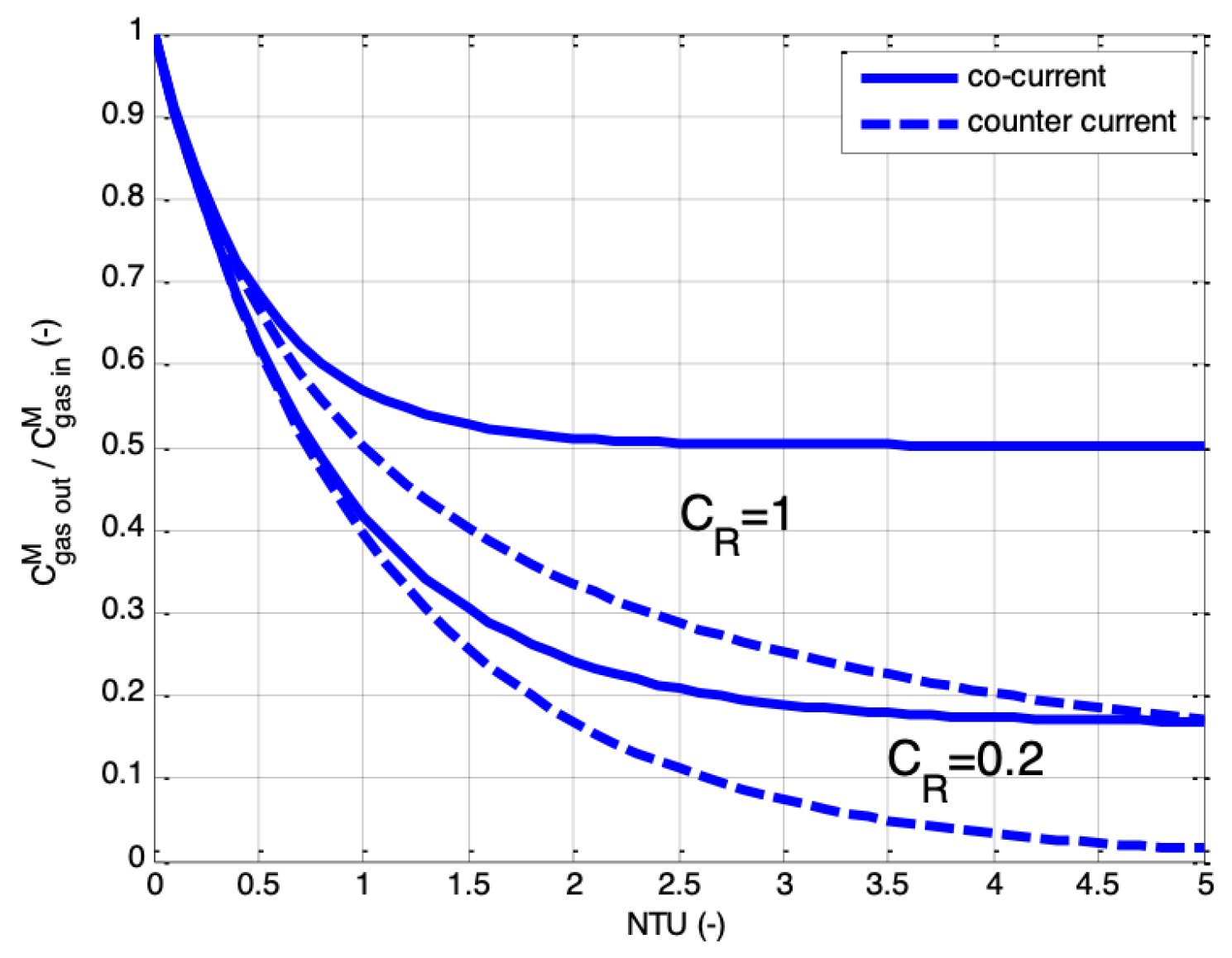
In Figure 4, we have shown the reduction in constituent concentration in the gas phase
R = C G ( L ) C G 0
versus N T U for values of c R of 1 and 0.2 . It is seen that for equal values of N T U , a lower value of R can be achieved in the case of the counter-current version. It should be noted that a counter-current version is not always possible. Only for sufficiently high liquid flow does the liquid flow downwards by gravity, despite the opposing shear force of the gas at the interface, which acts upwards. In Section 4, we shall derive a formula for this condition. The performance of the co-current can be improved by increasing N T U in combination with lower c R . It is also possible to connect co-current jointly rotating filters in series by which the performance becomes comparable to that of the counter-current version but with a more complicated in- and out-flow configuration for the liquid.

3. Mass Transfer Coefficients Derived from Diffusion Theory

The mass transfer coefficients k presented in the previous section represent an approximate description of mass transfer. The precise description follows from diffusion theory. In this section, we shall show how these approximate descriptions can be derived from diffusion theory. We also indicate its accuracy.
In the channels of the Rotational Absorber Device, we can distinguish two flow regions: the gas flow and the liquid flow, both parallel to each other. From a transfer point of view, both regions can be treated as flow along an impermeable wall on one side and an absorbing wall on the other. To derive the concept of the k-factor, both cases are similar. We therefore consider the diffusion problem described by a balance between convective transport and diffusion as
w C z = x ( D C x ) 0 x h 0 z L
where
C = C ( x , z ) = concentration of a constituent
w = w ( z ) = axial velocity
D = D ( x ) = diffusion coefficient
x = distance perpendicular to the wall
z = axial distance
h = width of the square channel according to Figure 2
L = length of the channel
At the impermeable wall we have
C x = 0 a t x = 0
while at the absorbing surface
C = C s ( z ) a t x = h
At channel entrance
C = C 0 ( x ) a t z = 0
Typical for the channels of the Rotational Absorber Device is that the width is much less than the length. Differences in concentration in the x-direction are small. This property will be used to derive an approximate description of the solution of (26)–(29). In fact, this approximation is similar to that applied in the theories of mechanics of thin plates and slender beams. It was first introduced in physics in the first half of the previous century [4].
Integrate (26) over x between x = 0 and x
D C x = C z Q ( x ) w i t h Q ( x ) = 0 x w d x
where we applied partial integration to introduce the approximation
0 x w C z d x = C z Q ( x ) 0 x Q 2 C z x d x + C z Q ( x )
because concentration variations in the x-direction are small. In (30), we applied boundary condition (27)
The average concentration or bulk concentration C ¯ is defined by
C ¯ = 0 h C w d x Q 1 with Q 1 ( x ) = 0 x w d x = Q ( x = h )
Applying partial integration, we can derive
C ¯ = Q 1 1 0 h w C d x = Q 1 1 0 h C d Q = C s 0 h C x Q Q 1 d x = C s + C ¯ z 0 h Q 2 Q 1 D d x
where in the last step, we used (30) and (31).
Result (33) can also be written as
Q 1 C ¯ z = k ( C ¯ C s )
where
k = 0 h ( Q / Q 1 ) 2 D d x 1
is mass transfer coefficient. This is the desired result with k properly defined. In (34), we can introduce
Q 1 = w 0 h
where w 0 is the average velocity of gas or liquid in the channel. In other words, using the concept of mass transfer coefficient as defined by (35) enables us to use as velocity of the bulk the average velocity. Hence, velocities in (2) and (3) are average velocities! The value of k, however, depends on the x-shape of the velocity distribution; (30) with Q = Q ( w ( x ) ) . Furthermore, while laminar flow D is constant, it will vary with x in turbulent flow. In Section 5, we will derive explicit expressions for k for the various cases occurring in the Rotational Absorber Device.

Comparison with an Exact Result

There is a simple way to verify the accuracy of description (34) for the case of homogeneous flow w = w 0 and constant diffusion coefficient D. Furthermore, we consider a general 3D configuration, as follows:
w C z = D ( 2 C x 2 + 2 C y 2 )
Boundary conditions are
x = 0 : C x = 0 ( non absorbing )
x = h : C = 0 ( full absorbing )
y = 1 2 h , + 1 2 h : C y = 0 ( non absorbing )
The boundary conditions describe a square channel with full absorption at one wall.
As the initial condition, we choose
C = C 0 ( x ) a t z = 0
The solution of Equation (37) can be constructed by the method of separation of variables. It leads to eigenfunctions in the x and y directions, which decay exponentially in the z-direction, as follows:
C = n = 0 n = 0 a n , k e ( α n , k z ) cos x h n + 1 2 π cos ( 2 y h k π )
where
α n , k = D π 2 w 0 h 2 ( n + 1 2 ) 2 + ( 2 k ) 2
The values of α n , k are determined by substituting (42) for z = 0 into boundary condition (41), multiplying the left- and right-hand sides with the eigenfunctions, integrating over the surface x y , and applying orthogonality, as follows:
1 2 h 1 2 h 0 h C 0 cos x h ( n + 1 2 ) π cos 2 u ¯ h k π d x d y = a n , k 0 h cos 2 x h ( n + 1 2 ) π d x 1 2 h 1 2 h cos 2 2 y h k π d y = a n , k
where the first double integral yields the RHS of (43) and the second double integral yields unity. From (44), it can be verified that for the symmetrical distribution of C 0 , with respect to y = 0 , we obtain α n , k = α n , 0 . The distribution of the concentration is then constant in the direction y parallel to the absorbing surface over the entire length z. That is also the situation described in (26)–(29). More importantly, from solutions (42) and (43), it can be concluded that higher eigenfunctions decay considerably faster with z than the lowest one, which corresponds to n = 0 and k = 0 . After a relatively short distance from the inlet z = 0 , the concentration can be described by
C = α 0 , 0 e π 2 D z 4 w 0 h 2 cos ( π x 2 h )
The average concentration reads as
C ¯ = C 0 ¯ e π 2 D z 4 w 0 h 2
Compare this result now with that of the k-based model. According to the description of the k-based model of (34)–(35) with assumptions w = w 0 and boundary condition (39) (note: C s = 0 , Q = w 0 x , Q 1 = w 0 h 2 and k = 3 D h )
d C ¯ d z = 3 D C ¯ h 2 w 0
with, as solution,
C ¯ = C 0 ¯ e 3 D w 0 z h 2
When we compare (46) and (48), we see that the exact solution (46) predicts a decay length of 4 w 0 h 2 π 2 D = 0.4 w 0 h 2 D , while the approximate k-based model reveals a decay length of 0.33 w 0 h 2 D . The deviation is 8%, which is well acceptable for engineering applications, noting that all other parameters suffer from some degree of uncertainty in actual values. A general conclusion is that the k-model approach with k defined by (35) works quite well. In the next section, we will discuss the flow situations in the channel and derive explicit expressions for k to be used in the formula of Section 2.

4. Fluid Flow in the Channels of the Rotational Absorber Device

To evaluate the parameters which determine the molecular transport in the channels of the Rotational Absorber Device, the fluid flow needs to be described. A distinction can be made between the gas flow section and the liquid flow section. We focus on the square channel configuration and later compare results with those of the cylindrical channel. In the square channel, the liquid flow basically occurs in a thin layer a tens of microns in size, which covers one side of the channel. The gas flow covers the remaining section, which is by a good approximation the entire square channel of width h, as the liquid part covers only a small part of the channel area. The flow in the gas section can be laminar or turbulent, depending on what the Reynolds number is.For a circular channel, this is
R e G = ρ G w G d μ G
where
ρ G = gas density in [ kg / m 3 ]
μ G = dynamic viscosity [ Pas ]
w G = average gas velocity [ m / s ]
d = diameter of circular channel [ m ]
The gas velocity is typically 2 to 5 [ m / s ] in practical applications. The dynamic viscosity is rather constant in value for various kinds of gases and amounts to about 1.8 · 10 5 [ kg / ( ms ) ] . The channel diameter is about 2 · 0 3 [ m ] while ρ G heavily depends on pressure. For air at atmosphere pressure, we have ρ G = 1.3 [ kg / m 3 ] , which increases proportionally with pressure P G . Taking w g = 4 [ m / s ] , one calculates
R e G = 580 R e G = 5800 when P G = 1 bar when P G = 10 bar
The flow will be laminar for R e G 2000 and turbulent for R e G 2000 . Both cases can occur in applications of the Rotational Absorber Device. The flow on the liquid side is generally laminar. We first consider the laminar flow case both for gas and liquid and later turbulent gas flow.

4.1. Laminar Flow in the Gas Section

From a fluid mechanical point of view, the laminar flow case is the simplest one to analyse and describe. The velocity profile in the gas section will be of a parabolic type. Assuming zero-slip at the non-absorbing wall and absorbing surface (the latter because liquid velocities are very low), the velocity in the equivalent square channel of Figure 2 will be
w g = 6 w ¯ G 1 x h x h
where w ¯ G is the average velocity and h the height of the square channel. Implementing this in the k-formula Equation (35) and taking D = D G as constant, we have
k G = 35 13 D G h
which is a bit lower than the value obtained with constant w G = w 0 over the channel cross-section, solution (48). The shear force τ 0 which the gas executes on the liquid surface and the resulting pressure drop Δ P E are given by
τ 0 = μ G w G x | x = 0 = 6 w ¯ G μ G h = 12 π w ¯ G μ G d
Δ p G = 4 τ 0 L h = 24 L μ G w ¯ G h 2 = 96 π L μ G w ¯ G d 2
where we used (1) to replace h by d. In (54), we assumed that τ 0 acts on all four sides of the square channel. It is noted that there are exact solutions for laminar flow in pipes and these lead to coefficients of 8 and 32 instead of 12 π = 6.8 and 96 π = 30.6 in the above equations, respectively; that is, they are 17% and 5% higher, respectively. The formulae appropriate for laminar flow in pipes instead of (53) and (54) are therefore preferred.

4.2. Laminar Flow in the Liquid Section

The liquid flow can be described according to a thin film along a surface of large two-dimensional extent. The liquid flows downwards due to gravity, while at its outer surface due to the gas flow, a shear force τ 0 acts, either downwards (co-current situation) or upwards (counter-current situation). Our sign convention is that τ 0 is positive in value in the downward direction (the co-current case). A solution for the laminar velocity distribution is obtained by applying film theory to the Navier–Stokes equations, thereby taking account of viscous forces [5,6]:
w L = ρ L g δ h x 1 2 x 2 + τ 0 x μ L 1
where
x = distance from the wall [ m ]
ρ L = liquid density [ kg / m 3 ]
g = gravitational acceleration
μ L = dynamic viscosity liquid [ Pas ]
τ 0 = shear force gas [ Pa ]
δ h = thickness of the film [ m ]
The thickness of the film is related to the liquid flow in the channel Q L [ m 3 / s ] by
δ h = Q L w ¯ L h
where w ¯ L is average liquid film velocity which follows from the integration of (55) as
w ¯ L = μ L 1 1 3 ρ L g δ h 2 + 1 2 τ 0 δ h
Subsituting this result into (56) yields a cubic equation for δ h
1 3 ρ L g δ h 3 + 1 2 τ 0 δ h 2 = Q L μ L h
which can be solved numerically.
From solution (55), it is seen that if the axial velocity becomes negative, i.e., upwards, this will first happen at x = δ h , as follows:
w L ( x = δ h ) = 1 2 ρ L g δ h + τ 0 δ h μ L 1
Liquid flow in an upwards direction can only occur for a negative value of τ 0 , i.e., countercurrent flow. Clearly, such flow is unwanted, implying that a proper counter-current operation is only possible if
τ 0 < 1 2 ρ L g δ h
As δ h increases with liquid flow Q L , the above criterion for a proper countercurrent operation will be satisfied for a sufficient amount of liquid flow. Using (58), this can be calculated from (60).
The mass transfer coefficient of the liquid can be calculated by substituting solution (55) into Q L = 0 x w L d x and subsequently evaluating (35). However, the resulting description is quite elaborate. From solution (55), it is seen that the largest part of the velocity profile is linear, i.e., w L ÷ x . The linear velocity profile yields k = 5 D L δ h , where D L is the diffusion coefficient appropriate for the liquid. For a constant profile, one has k = 3 D L δ h . It reflects the situation that transport has to take place over the entire thickness, whereas in the linear case, more of the transport is near the absorbing surface. Considering the quadratic term in solution (55), we propose
k L = 4 D L δ h
where δ h follows from Equation (58).
Liquid is fed to the channels of the Rotational Absorber Device from stationary non-rotating injection points. As the channels rotate, this leads to a pulsation of the liquid velocity when entering the channels. The result is a wavy liquid flow from top to bottom, which is described in Section 5. The internal velocity circulations in the liquid layer enhance the diffusion through the liquid. The effect can be quantified by a diffusion-enhancement factor f e . The transfer coefficient for the liquid then reads as
k L = 4 D L δ h f e
where f e is specified by Equations (102) and (103).

4.3. Turbulent Flow in the Gas Section

For a sufficiently large Reynolds number, as in (49) and (50), the flow in the gas section will be turbulent.
In the centre part of the section, turbulent fluctuations are largest, but near the walls, they die out; close to the wall the flow will be laminar. This is reflected in the description of the diffusion coefficient, as follows:
D G t = κ u * x + D G
where
κ = Von K á rm á n s constant = 0.4
u * = τ 0 ρ G = shear velocity [ m / s ]
τ 0 = shear force executed by the gas on the wall [ Pa ]
x = distance from a solid wall [ m ]
D G = laminar diffusion coefficient appropriate for the gas [ m 2 / s ]
The first term on the right-hand side describes diffusion by turbulence, the second is laminar diffusion. The turbulent diffusion is generally large at a sufficient distance from the wall but diminishes as x 0 where the contribution of D G becomes important. In turbulent flow, the mean velocity profile is generally quite flat. We therefore assume w G to be constant, in which case the expression for the mass transfer coefficient is cf.Equation (35) becomes
k 1 = 0 h ( x / h ) 2 D G t d x
To evaluate the integral, we distinguish between the half-sections 0 x h 2 and h 2 x h δ h , where the first connects to the impermeable wall at x = 0 and the second at the absorbing liquid surface at x = h δ h .
(i)
For the region 0 x h 2 , we can write
k 1 1 = 0 d 2 ( x / h ) 2 κ u * x + D G d x = 1 4 κ u * 0 1 y 2 y + R e D * 1 d y
where we took x = h y / 2 and
R e D * = κ u * h 2 D G
is the Reynolds number based on shear velocity and diffusion coefficient. For turbulent flow at large Reynolds number R e D * will also be large. Evaluating the integral using an expansion involving small R e D * 1 and disregarding contributions of magnitude R e D * 1 directly compared to 1, we obtain
k 1 1 = 1 8 κ u * ( 1 2 R e D * 1 )
(ii)
For the region h 2 x h δ h , we can write
k 2 1 = h 2 h δ h ( x / h ) 2 κ u * ( h x ) + D G d x = 1 κ u * 2 δ h h 1 ( 1 1 2 y ) 2 y + R e D * 1 d y
where we took x = h h y / 2 . Integral (68) can be evaluated again using expansions based on small R e D * 1 . Disregarding terms of relative magnitude R e D * 1 directly compared to 1, we obtain
k 2 1 = 1 κ u * 7 8 + ln 1 1 R e D * + 2 δ h h
Adding the resistances k 1 for both parts of the gas section and again disregarding relative contributions of R e D * 1 , we finally obtain for k
k = κ u * 3 4 + ln 1 1 R e D * + 2 δ h h 1
The logarithmic term yields the largest contribution and it is entirely due to the diffusion process near the absorbing surface. Because of the reducing value of the turbulent diffusivity, when approaching this surface, it forms the main obstacle for transport to the liquid. The above analysis has been repeated for two opposite absorbing walls and for a cylinder with an absorbing wall all around. The only difference with result (70) was the factor 3 4 , which appeared to be 3 2 and 11 6 , respectively. These are relatively minor changes because the term ln Re D * is the dominant one. A more general derivation, which also took into account the logarithmic mean velocity profile instead of a constant profile, was presented in [7] (Equation (13.4.19)). The presented expression valid for a cylinder with a rigid non-wetted surface was
k = κ u * 1 1 + 1.1 ln R e D * 1
It yields values for k which are about 30% less than those obtained from (70) for δ h / h = 0 . The expression which is proposed to be used in this design is:
k = κ u * 1 1 + 1.1 ln 1 1 R e D * + 2 δ h h
This is an amended version of (71a), taking into account the effect of the wet surface and correcting (70) for the effect of a non-constant mean velocity profile. Note that for the cylindrical channel h = d in Equation (66), h equals the hydraulic diameter of the square channel.
For turbulent flow in a channel, the shear force exerted by the gas on the walls can be described by
τ 0 = ρ G u * 2 = 1 2 ρ G f 0 w ¯ G 2
where w ¯ G is the average gas velocity in the channel and f 0 is the friction factor for a dry channel
f 0 = 0.0791 R e G 4
where R e G 4 is defined by Equation (49) for a cylindrical channel. For a non-cylindrical channel, we have to use the hydraulic diameter of the channel d H , which equals 4 times the cross-sectional area divided by the circumference. For the square channel with heights h, we have d H = h .
Relation (73) has been confirmed by in-house experiments using horizontal glass pipes. We also tested the case that water was injected leading to a liquid film at the bottom of the horizontal pipe. The friction increased and could be summarised by the empirical relation
f = f 0 ( 1 + 0.56 F 0 0.82 ) w i t h F 0 = 10 4 μ L w l f 0 ρ G w G 2 d
Replacing f 0 by f in Equation (72) yields friction in the case of liquid flow along a wall. The pressure drop over the channel is given by
Δ ρ G = 4 L d H τ 0
where L is channel length.

4.4. The Contact Surface in Circular Channels

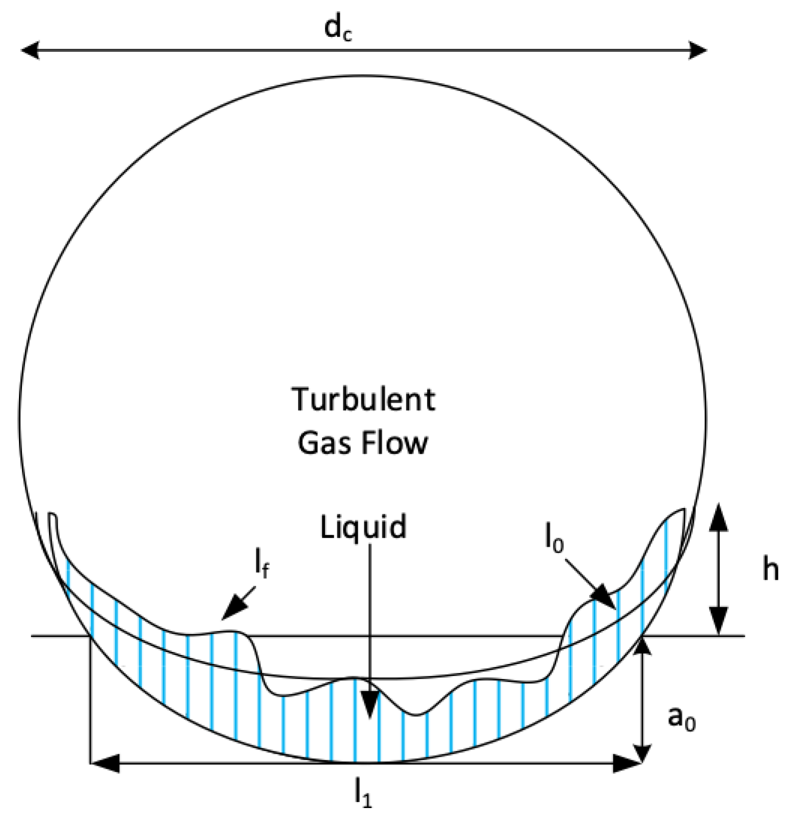
In the derivation of expressions for absorbance in Section 2, we considered a square section as representative of the shape of the channels in the Rotational Absorber Device. The consequence is that the contact surface between liquid and gas is represented by h L . Channels in the Rotational Absorber Device are generally circular. A liquid film forms at the radially outward part of the channel; see Figure 5.
Without surface tension and a flat surface without waves the liquid film will be a straight horizontal line. Surface tension heightens the liquid film at the corners and thereby increases the contact line. A wavy surface further increases the surface but this effect will be conservatively disregarded. The fraction of wet surface is defined as
β w = l 0 π d c w i t h l 0 = l 1 + 2 h 1
where l 1 is the length without the effect of surface tension, d c = d , and h the heightening along the side walls by the surface tension. We can write
l 1 = 2 δ h d c 2 3 a n d h 1 = 0.6 σ ρ l Ω 2 R 0
where R 0 is the radial position of the channel. The first equation follows from goniometric calculations based on a stationary area of liquid with a flat surface at the bottom of a circular pipe and δ h being defined as the average height as calculated from Equation (58) with h = d ; the second equation has been obtained from relations presented in ([8], p. 66). The above formula allows one to calculate the correction in the N T U formula of Section 2. These were based on the square channel configuration of Figure 2, in which case the ratio of wetted length and cross-sectional area equals 1 / h . For the circular channel, this ratio is 4 β w / d so that the N T U formula (22) becomes
N T U = K L l 0 Q G M = 4 β w k G L d w G ( 1 + α )
Note that k G and k L express the transport per unit surface. Their values are only slightly influenced by the shape of the channel and the size of the liquid surface.

5. Wave-Enhanced Transfer in the Liquid Film

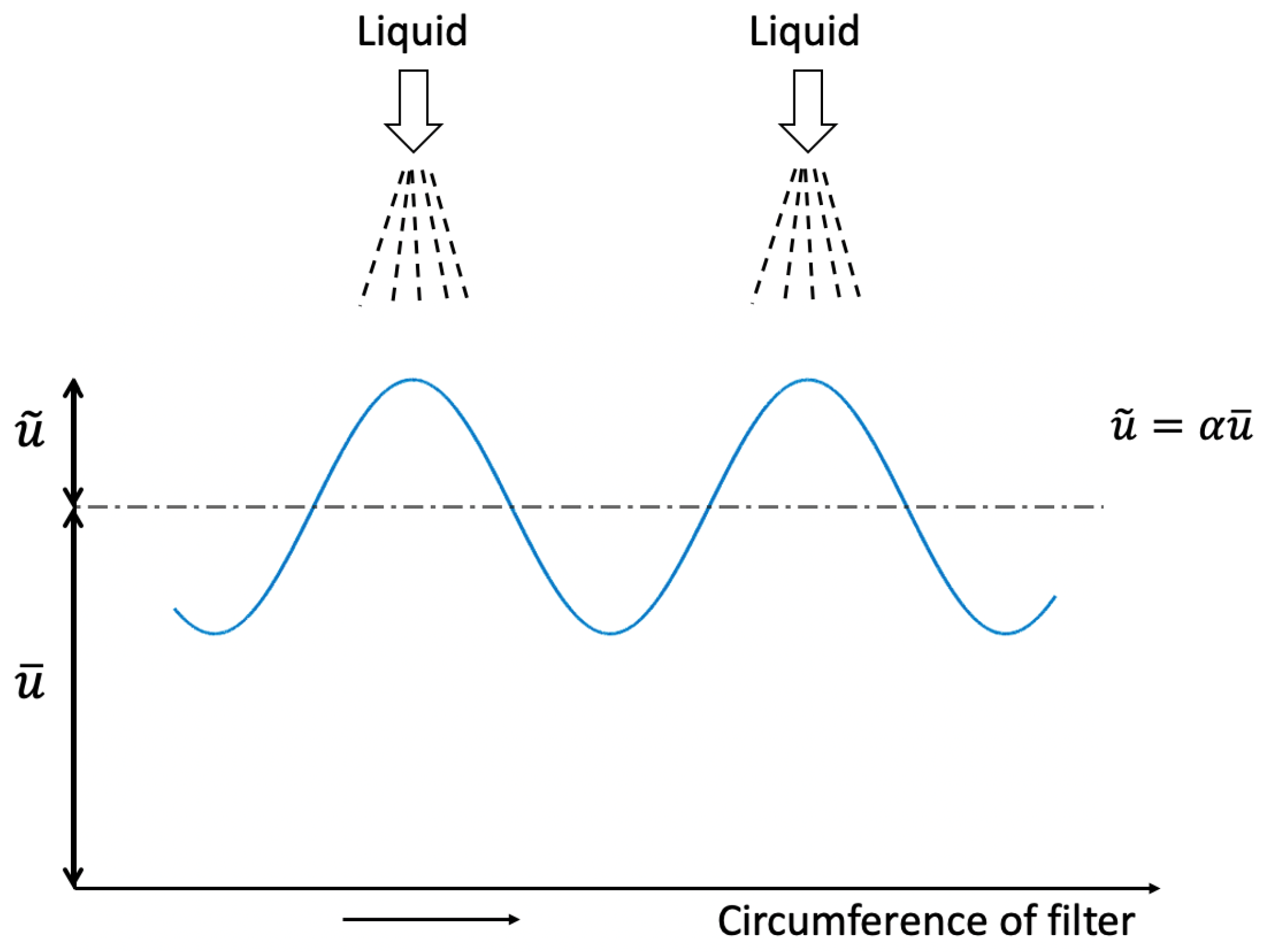
In the Rotational Absorber Device, scrubbing liquid is injected above the rotating cylinder. While the injection takes place from a stationary position, the cylinder rotates. In general, the liquid injection will be homogeneously distributed over the circumference of the rotating cylinder. As a consequence, the channels of the rotating cylinder will receive liquid in a non-stationary time-dependent manner. This causes waves in the liquid film that propagate downwards. They lead to secondary fluctuating velocities in the film and they will enhance the diffusion from gas into the liquid. The aim of this section is to quantify this process.

5.1. Generation of Waves

Waves are due to the stationary liquid injection on top of the rotating element; see Figure 6.

5.2. Wave Motion

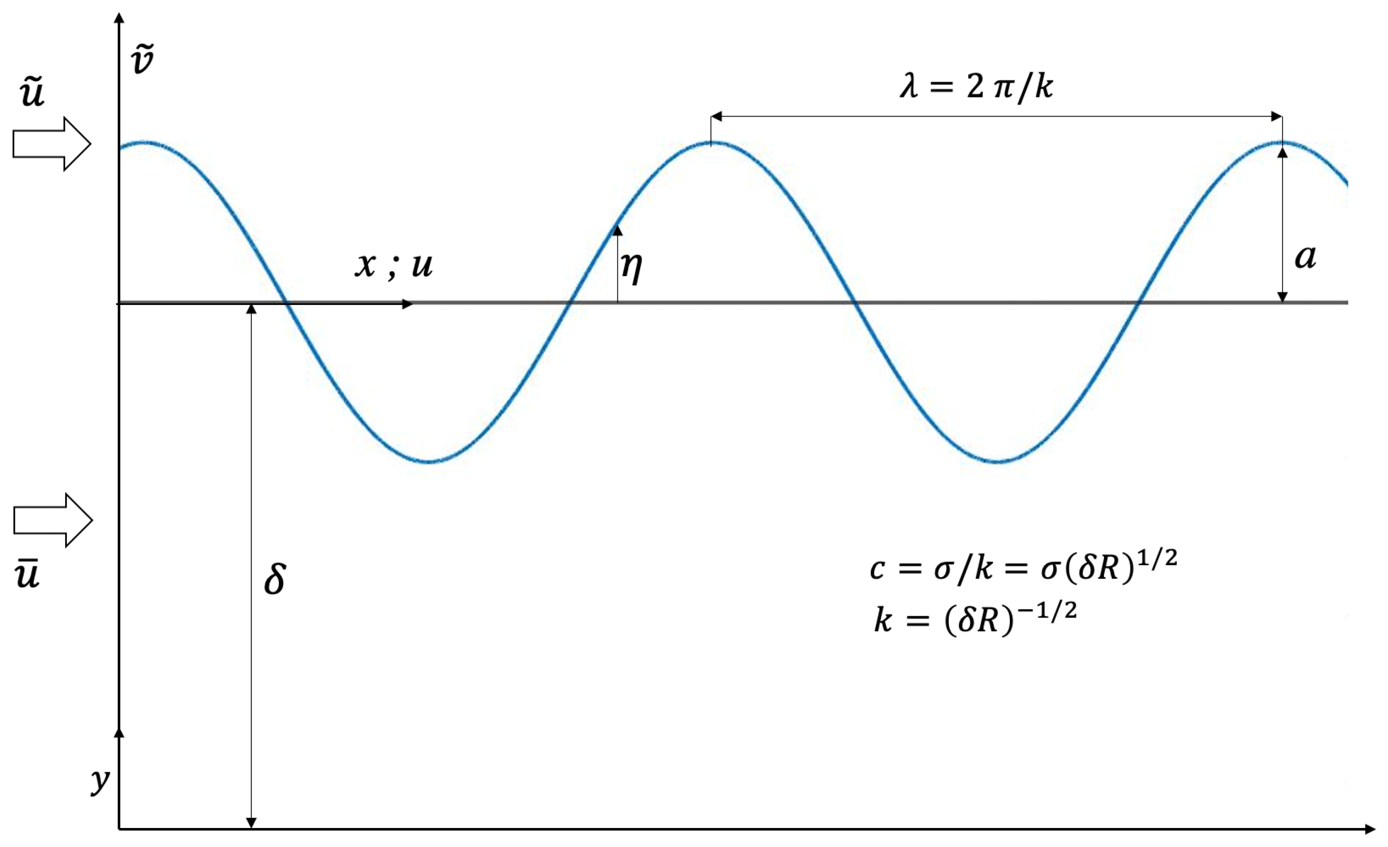
The theory of gravity waves in liquids has been extensively described by [9,10]. The theory of gravity waves can directly be translated to that of centrifugal waves by replacing g by Ω R . Furthermore, in our case, we have a thin layer compared to the radius R so that we can apply the shallow water limit. The solutions thus obtained are given in formula (79a)–(79c) and illustrated in Figure 7.
u = u ¯ + u ˜ cos ( k x σ t ) f o r 0 x L
y = a cos ( k x σ t ) w i t h a = 1 σ δ R 1 2 u ˜
v ˜ = y δ u ˜ sin ( k x σ t ) f o r 0 y δ
In the case of n injection points in the circumference, we will have
σ = n Ω
while
u ˜ = α w u ¯
where α w is the amplitude of fluctuating liquid entering the channel relative to the mean liquid velocity: u ¯ = w ¯ L . We thus have
a = α W n Ω δ R 1 2 u ¯ w i t h v ˜ = y δ α W u ¯ δ R 1 2 sin ( k x n Ω t )

5.3. Decay of Wave Motion

The viscosity of the liquid leads to decay of the wave in x-direction: ([9] p. 627 and [10] p. 314). This decay can be described by multiplying the solutions for fluctuating velocities and wave height by the factor
e ϵ 1 x L w i t h ϵ 1 = 2 ν L L ( R δ ) 3 2 n Ω
Shear force by the gas flowing over the waves leads to decay for counter-current flow and increase for co-current flow (own derivation)
counter - current : e ϵ 2 x L
co - current : e + ϵ 2 x L
where
ϵ 2 = τ 0 L 2 ρ L Ω 2 R 2 δ
In co-current flow the total value of ϵ 1 + ϵ 2 can become negative, in which case the amplitude of the wave increases exponentially with length. That is, when
ϵ 2 > ϵ 1
or
Ω < τ 0 4 η L δ R 1 2
The liquid film may break from the wall and become a mist, an unwanted situation for optimal absorption. The frequency of the co-current Rotational Absorber Device should preferably be larger than the above value of τ 0 ( δ / R ) 4 η L . In case of counter-current flow the amplitude of the wave will always decrease.

5.4. Fluid Particle Path

As described in [9], each fluid particle follows an elliptic harmonic path defined by
x 1 = a k δ cos ( k x n Ω t )
x 2 = a y δ sin ( k x n Ω t )
x 1 l 1 2 + x 2 l 2 2 = 1
where the semi-axis of the ellipsoid is defined by
l 1 = a k l 2 = a
The period of one cycle is
T = 2 π n Ω
To describe the effect of fluid particle motion on diffusion, we are only concerned with motion in the y-direction, i.e., perpendicular to the wall, which is the direction where diffusion is the transport of the admixture. During one cycle, the fluid particle will be displaced in the y-direction by a distance of 2 a . At any y-position, we may write
Δ s = 2 a s δ
as displacement over one cycle. Hence,
Δ s Δ t = a n Ω s π δ
or in infinitesimal terms,
d s d t = a n Ω π δ s
with boundary condition
s = s 0 = δ A t t = 0
The solution is
s = δ e 2 a n Ω t c π δ
The displacement decays because the fluid velocity decays as 1 / y

5.5. Enhanced Diffusion by Wave Motion

The stirring as a result of wave motion described by the solution for s can be translated to the enhancement of the laminar diffusion [11]. We can write
τ c = D L t s 2 = D L t δ 2 e 2 a n Ω t c π δ
where t is time of diffusion and τ c is a dimensionless paramater, which is of O ( 1 ) . Diffusion has been practically completed when t t c . We can determine the value of τ c by considering the case of zero wave-induced motion. For zero wave flow, i.e., for Ω = 0 in Equation (96), τ c = D L t c δ 2 . The transfer coefficient k L is related to t c as k L = δ t c . As we know that for laminar diffusion k L = 4 D L δ , cf. Equation (61), we find that
τ c = 1 4
Diffusion over the liquid layer is completed when
τ c = 1 4 = D L t δ 2 e 2 a n Ω t c π δ
This relation can be converted to one for k L (because k L = δ / t c ), which reads as
k L = 4 D L δ 2 f e
where fe is the solution of the irreducible equation
f e = e P e / f e
P e being the Peclet number defined by
P e = α w w ¯ L δ 2 π D L
The Peclet number can be corrected for decay by viscosity and gas shear by multiplying w ¯ with the decay function presented in Section 5.3. The Peclet number describes the enhancement of diffusion by wave motion, quantified by the factor f e . The larger P e is, the larger the enhancement becomes. For P e < < 1 , f e approaches unity, which corresponds to diffusion by molecular motion only. For P e = 10 , 10 2 , 10 3 (100) yields for f e values of about 6 , 29 , and 190, respectively.

6. The Role of Rotation

In the Rotational Absorber Device, the channels in which the absorption process takes place rotate as a rigid cylindrical body around the symmetry axis of the cylinder. The formulae for absorption presented in Section 2 and Section 3 do not show an explicit dependency on the angular speed of the body. Yet rotation has an important function to fulfil.

6.1. Liquid Pressing to Outer Channel Wall

Rotation leads to a centrifugal force, which presses the liquid to the radially outward wall of the channel. It prevents the blocking of the channel by capillary forces, which can create a bridge of fluid over the entire channel cross-section.

6.2. Wave Motion Generated by Stationary Liquid Injection

As described in Section 5, stationary liquid injection on top of the rotating cylinder leads to waves in the liquid layer along the walls of the channels. When the rotation becomes too small in a co-current absorber, the liquid layer may separate from the wall and form a mist. This situation is not preferred and is prevented by choosing a sufficiently larger value of Ω : cf. Equation (88).

6.3. Limitation of the Wave Amplitude of the Liquid Layer

Wave motion in the liquid layer will increase the transport coefficient of the liquid. This is especially welcome in situations where diffusion in the liquid layer is the limiting factor for the overall absorbance performance of the Rotational Absorber Device. At the same time, the amplitude of the waves must not become too large in comparison with the average thickness of the liquid layer. It hampers the diffusion through the layer when it is thickest in value. It is preferred to keep a δ < 0.1 , where the amplitude is specified by Equations (79)–(81).

6.4. Liquid Separation from the Gas

At the bottom of the cylinder, the liquid leaves the channels. Here, it is propelled radially by rotation in the form of droplets. The droplets arrive in a collection chamber positioned in the side wall of the housing of the rotational absorbing device; see Figure 1.

6.5. Particle Separation

The rotational absorbing device can also serve as a separator of particles from gases. The driving force for separation is rotation. The dimensioning of the rotational absorbing device as a particle separator has been reported in [3]. The functions of absorption and particle separation can be combined in one Rotational Absorber Device. This combination is of interest to certain applications [12].

7. Application in Design

Application of the formula is illustrated for the case of removing C O 2 from flue and combustion gases. Inlet concentration of C O 2 is 12 % and the target is to reduce this concentration by a factor of 100 to a concentration of 0.12 % . The pressure is atmospheric and the temperature is 70 °C. In line with conditions often seen in applications of the tray and packed columns, the absorber fluid is a mixture of Amine ( M E A ) in water at 30 % by weight. The flow rate of liquid and gas is Q L M Q G M = 4.5 , which corresponds to a mol ratio of M E A to C O 2 of 5. The Henry constant H M decreases strongly with C O 2 at the contact surface between liquid and gas [1]. It ranges from 0.46 at the inlet to 23 at the outlet; see Table 2.6 at [1]. In the present approximate analysis, a conservative average value of H M = 1 is taken over the entire height of the unit. The value of c R calculated from Equation (17) is then c R = 0.22 . The value of N T U necessary to arrive at a reduction of a factor of 100 in the case of a counter-current absorber unit can be calculated from Equation (52). For c R = 0.22 , one obtains N T U = 5.6 . This value applies to the Rotational Absorber Device, the tray column, and the packed column. The formulae specifying N T U as a function of internal parameters such as mass transfer coefficients and velocities enable the dimensions and operating conditions of the absorber to be determined.
According to Equation (78), we have
N T U = K L l 0 Q G M = 4 β w k G L d w G ( 1 + α )
where according to Equation (22)
α = ρ G k G M L H M ρ L k L M G
We assume that the wetted surface in the channels of the Rotational Absorber Device equals 1 4 of the circumference, in which case 4 β W = 1 in Equation (104). For the gas velocity in the channels, w G = 2 m / s , which is in line with velocities in the tray and packed columns. The external diameter of the absorbers of all three technologies is thus similar. The difference will be the required height to achieve the targeted reduction in C O 2 concentration.
The diameter of the channels in the Rotational Absorber Device is taken as d = 1.3 mm . The Reynolds number calculated from Equation (49) is about 130 (dynamic viscosity of the gas μ G = 2 · 10 5 Pas , density of the gas ρ G = 1 kg / m 3 ) implying that the flow is laminar. Noting that the diffusion constant of the gas D G = 1.8 · 10 5 m 2 / s and taking for h of the equivalent square channel in Figure 2 value somewhat less than the diameter d of the circular channel, i.e., h = 1.2 mm , one calculates for the mass transfer coefficient of the gas from Equation (52) k G = 4 · 10 2 m / s , which corresponds to k G M = 1.4 mol / ( m 2 s ) (molecular weight of the gas M G = 28 g / mol ).
To calculate the mass transfer coefficient of the liquid k L according to Equation (61) and mass transfer ratio α according to Equation (105), we need to know the thickness of the liquid layer in the channels δ h . Its value follows from Equation (58). In this equation, the liquid flow in the channel Q is given by
Q L = Q L Q G w G h 2
For Q L M Q G M = 4.5 , one has Q L Q G = 3.7 · 10 3 (molecular weight of the liquid M L = 23 g / mol , density of the liquid ρ L = 10 3 kg / m 3 ). The shear stress τ 0 executed by the gas on the walls and liquid layer has been specified by Equation (53) and is found to be τ 0 = 0.21 Pa . The pressure drop per unit length follows from Equation (54) as Δ P G / L = 180 Pa / m . Taking g = 10 m / s 2 and for the dynamic viscosity of the liquid μ L = 2 · 10 3 Pas , one calculates from Equation (58) as thickness for the liquid layer δ h = 0.13 mm . The diffusion coefficient of the liquid layer D L = 0.33 · 10 8 m 2 / s so that k L = 10.2 · 10 5 m / s and k L M = 4.1 mol / ( m 2 s ) . For H M = 1 , the value for α obtained from Equation (105) becomes α = 0.34 .
Having specified the values of 4 β , k G , d, w G , and α , the required height of the Rotational Absorber Device L to obtain a value for N T U of 5.6 is calculated from Equation (104) as 0.49 m . With this height, the inlet concentration of C O 2 is estimated to be reduced by a factor of 100. The calculated height is considerably less than the height of the tray and packed columns seen in practice. Their height can raise from 20 m to 30 m under similar conditions [1]. In the case of the packed column, the large height can be explained from the size of the packing material, such as Raschig rings and Pall rings [1]. Sizes are of the order of 10 mm . The gas flow between the packings takes place in channels which are 5 to 10 times larger than those of the Rotational Absorber Device. The required height of the absorber calculated from Equation (104) is proportional to d 2 , d explicitly according to Equation (104) and once again d because of dependency of k G on d according to Equation (52). For a channel height which is 5 to 10 times larger, the required height of the absorber becomes 25 to 100 times larger.

8. Conclusions

Applying the principles of absorption in small channels which are packed together in a rotating cylinder forms the core of the Rotational Absorber Device. Its function is based on well-established physics and is confirmed by full-scale applications in specific areas of industrial absorption [3]. The main advantage over existing absorption techniques is its compact size. At other equal dimensions, its height can be 25 times less than that of tray and packed columns which can be as high as 40 m [1]. Particularly interesting is application in the emerging market of C O 2 capture from flue gasses of fossil fuel combustion installations to mitigate climate change [13].

Funding

This research received no external funding.

Informed Consent Statement

Not applicable.

Data Availability Statement

No new data were created or analyzed in this study. Data sharing is not applicable to this article.

Acknowledgments

The author wishes to thank V. H. J. Brouwers and G. M. Janssen for their contribution to the preparation of this article.

Conflicts of Interest

The author declares no conflict of interest. Author J.J.H. Brouwers was employed by the company Romico Hold VBA., 6226 GV, Maastricht, The Netherlands. The remaining authors declare that the research was conducted in the absence of any commercial or financial relationships that could be construed as a potential conflict of interest.

References

  1. Kohl, A.; Nielsen, R. Gas Purification; Gulf Professional Publishing: Houston, TX, USA, 1997. [Google Scholar]
  2. Brouwers, J.J.H. Rotational Absorber Device and Method for Scrubbing an Adsorbate from a Gas. European Patent EP3624923B1, 14 April 2021. Patent Granted in Countries Worldwide. [Google Scholar]
  3. Brouwers, J.J.H. Innovative Methods of Centrifugal Separation. Separations 2023, 10, 181. [Google Scholar] [CrossRef]
  4. Bramley, A. On the Theory of the Separation of Isotopes by Thermal or Centrifugal Methods. Science 1940, 92, 427–428. [Google Scholar] [CrossRef] [PubMed]
  5. Willems, G.P. Condensed Rotational Cleaning of Natural Gas. Ph.D. Thesis, Eindhoven University of Technology, Eindhoven, The Netherlands, 2009. Available online: https://pure.tue.nl/ws/portalfiles/portal/2808690/200911885.pdf (accessed on 1 January 2020).
  6. Mondt, E. Compact Separator of Dispersed Phases. Ph.D. Thesis, Eindhoven University of Technology, Eindhoven, The Netherlands, 2005. Available online: https://pure.tue.nl/ws/files/3339334/200513466.pdf (accessed on 1 January 2020).
  7. Bird, R.B.; Stewart, W.E.; Lightfoot, E.N. Transport Phenemena; John Wiley and Sons: New York, NY, USA, 1960. [Google Scholar]
  8. Batchelor, G.K. An Introduction to Fluid Dynamics; Cambridge University Press: New York, NY, USA, 2006. [Google Scholar]
  9. Lamb, H. Hydrodynamics; Cambridge University Press: Cambridge, UK, 1932. [Google Scholar]
  10. Basset, A.B. A Treatise on Hydrodynamics; Bell and Co., Ltd.: Cambridge, UK, 1888; Volume 2. [Google Scholar]
  11. Villermaux, E. Mixing Versus Stirring. Annu. Rev. Fluid Mech. 2019, 51, 245–273. [Google Scholar] [CrossRef]
  12. Brouwers, J.J.H. Separation and Disinfection of Contagious Aerosols From the Perspective of SARS-CoV-2. Separations 2021, 8, 190. [Google Scholar] [CrossRef]
  13. Koonin, S.E. Unsettled; BenBella Books, Inc.: Dallas, TX, USA.
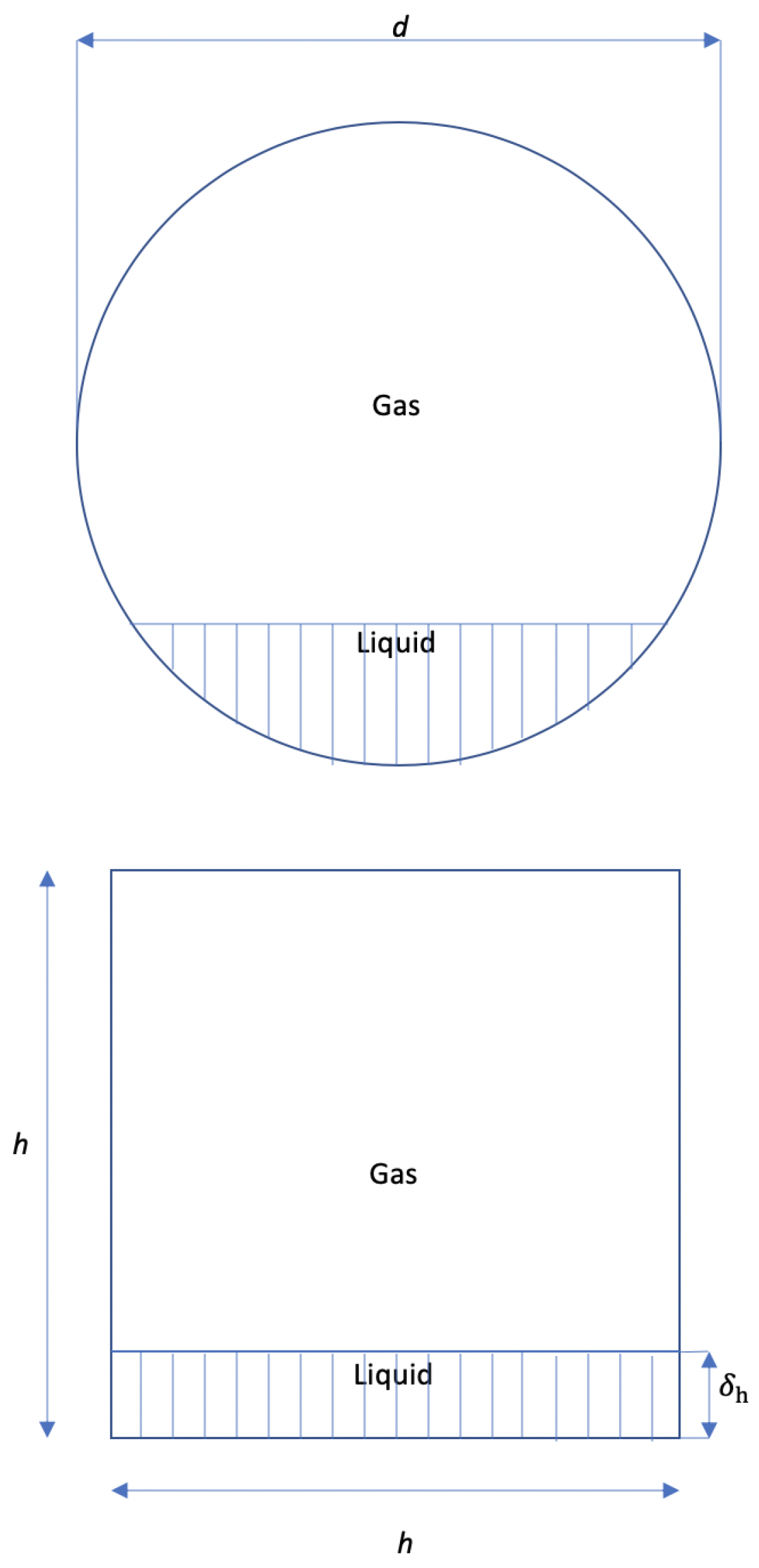
Figure 1. Schematic drawing of the counter-current Rotational Absorber Device [2,3].
Separations 11 00338 g001
Figure 2. Circular channel and “equivalent” square channel.
Separations 11 00338 g002
Figure 3. Vertical cross-section of part of a single channel.
Separations 11 00338 g003
Figure 4. Reduction in constituent concentration.
Separations 11 00338 g004
Figure 5. h is heightening by surface tension, a 0 static liquid level in the absence of surface tension, l 0 length of the liquid contact line in the absence of fluctuations, and l f length of the contact line in case of fluctuations.
Separations 11 00338 g005
Figure 6. Liquid injection on top of the rotating element: u ¯ is the average speed and u ˜ is the fluctuating part seen in a frame that rotates with the rotating cylinder.
Separations 11 00338 g006
Figure 7. Wave motion in the liquid layer.
Separations 11 00338 g007
Disclaimer/Publisher’s Note: The statements, opinions and data contained in all publications are solely those of the individual author(s) and contributor(s) and not of MDPI and/or the editor(s). MDPI and/or the editor(s) disclaim responsibility for any injury to people or property resulting from any ideas, methods, instructions or products referred to in the content.