Article

Semi-Analytical Solution of Two-Dimensional Viscous Flow through Expanding/Contracting Gaps with Permeable Walls

by
Mohammad Mehdi Rashidi
1,2,*,
Mikhail A. Sheremet
3,
Maryam Sadri
1,
Satyaranjan Mishra
4,
Pradyumna Kumar Pattnaik
5,
Faranak Rabiei
6,
Saeid Abbasbandy
7,
Hussein Sahihi
8 and
Esmaeel Erfani
9
1
Institute of Fundamental and Frontier Sciences, University of Electronic Science and Technology of China, Chengdu 610054, China
2
Faculty of Mechanical and Industrial Engineering, Quchan University of Technology, Quchan, Iran
3
Laboratory on Convective Heat and Mass Transfer, Tomsk State University, 634050 Tomsk Oblast, Russia
4
Department of Mathematics, Siksha ‘O’ Anusandhan Deemed to be University, Bhubaneswar, Odisha 751030, India
5
Department of Mathematics, College of Engineering and Technology, Bhubaneswar, Odisha 751029, India
6
School of Engineering, Monash University Malaysia, Selangor 47500, Malaysia
7
Department of Applied Mathematics, Faculty of Science, Imam Khomeini International University, Qazvin 34149-16818, Iran
8
Department of Mathematics, Science and Research Branch, Islamic Azad University, Tehran, Iran
9
Graduate Student of Mechanical Engineering, Mechanical Engineering Department, Engineering Faculty, Bu-Ali Sina University, Hamedan, Iran
*
Author to whom correspondence should be addressed.
Math. Comput. Appl. 2021, 26(2), 41; https://doi.org/10.3390/mca26020041
Submission received: 2 April 2021 / Revised: 20 May 2021 / Accepted: 20 May 2021 / Published: 23 May 2021
(This article belongs to the Special Issue Advances in Computational Fluid Dynamics and Heat & Mass Transfer)

Abstract

:
In this research, the analytical methods of the differential transform method (DTM), homotopy asymptotic method (HAM), optimal homotopy asymptotic method (OHAM), Adomian decomposition method (ADM), variation iteration method (VIM) and reproducing kernel Hilbert space method (RKHSM), and the numerical method of the finite difference method (FDM) for (analytical-numerical) simulation of 2D viscous flow along expanding/contracting channels with permeable borders are carried out. The solutions for analytical method are obtained in series form (and the series are convergent), while for the numerical method the solution is obtained taking into account approximation techniques of second-order accuracy. The OHAM and HAM provide an appropriate method for controlling the convergence of the discretization series and adjusting convergence domains, despite having a problem for large sizes of obtained results in series form; for instance, the size of the series solution for the DTM is very small for the same order of accuracy. It is hard to judge which method is the best and all of them have their advantages and disadvantages. For instance, applying the DTM to BVPs is difficult; however, solving BVPs with the HAM, OHAM and VIM is simple and straightforward. The extracted solutions, in comparison with the computational solutions (shooting procedure combined with a Runge–Kutta fourth-order scheme, finite difference method), demonstrate remarkable accuracy. Finally, CPU time, average error and residual error for different cases are presented in tables and figures.

1. Introduction

Significant interest has been paid to the analysis of nonlinear challenges in different fields of nature and engineering. To solve this type of problem, the wide group of analytical solutions and computational simulations has been considered. A general analytical method to solve the non-linear differential equations is the perturbation technique [1,2]. Practical problems such as solution of the Bernoulli problem [3] have been solved by the perturbation procedure. However, the perturbation methods have their own limitations. In the analytic perturbation method, perturbation parameters should be exerted into the equation and this is the downside of the perturbation methods. Therefore, developing a new kind of nonlinear analytical method that requires no perturbation parameter is essential. However, with the development of parametric computational software including MATHEMATICA, MAPLE, MATLAB, etc., approximate analytical techniques for nonlinear challenges have been approved by various scientists. The Adomian decomposition method (ADM) [4,5,6], variational iteration method (VIM) [7] and homotopy perturbation method (HPM) [8] are a few types of analytical method. These semi-numerical-analytical methods provide promising results in solving a set of problems with fast and efficient convergence. Certainly, each of these methods has its strengths and weaknesses.
Thus, Zhou [9] and Pukhov [10] were among the early researchers to apply the differential transform method to engineering challenges. This approach differs from the conventional Taylor series technique that illustrates expansion of the derivatives. By employing the DTM, the control equations are transformed to a recurrent relation and the border restrictions reduce into a system of algebraic equations. Due to the independence of the DTM from the existence of a small parameter, it can overcome the limits of perturbation techniques. Chen and Ho [11] defined a closed-view series solution for linear and nonlinear initial value problems (IVPs) with development of this method for PDEs. The DTM is employed to work out Burgers’ and nonlinear energy transport equations, the heat boundary-layer along a plane surface and several initial-value problems [12,13,14,15]. Rashidi et al. [16] analyzed MHD laminar motion in a partially porous duct employing the DTM. In 1992, the homotopy analysis method (HAM) dealing with a homotopy in topology was proposed to generate an analytic technique for nonlinear challenges [17]. Recently, the HAM has been used to work out different nonlinear problems [18,19]. The optimal homotopy asymptotic method (OHAM) is a new analytical procedure that was developed by Marinca et al. [20]. The independence of this technique from the small parameter has resulted in the power of the OHAM in solving nonlinear differential equations [21,22]. By this technique, an effective method for managing the convergence of approximation series and adjusting convergence regions is available. Hence in the current paper, the authors chose this boundary value problem to compare three analytical methods (DTM, OHAM, HAM). Another semi-analytical method that can be applied for this problem is the reproducing kernel Hilbert space method (RKHSM); recently many researchers have implemented this method on complicated problems [23,24,25,26,27]. As a general conclusion, for CPU time, the DTM has the minimum CPU time in all of the mentioned methods. Numerical methods like the FDM are more general and robust, but when changing any physical parameter, one must perform the simulation again; however, in analytical methods when changing physical parameters there is no need to redo the calculation. Another limitation of analytical problems might be related to solving PDEs; some of them can only be applicable to ODEs that can be obtained from the similarity solutions for converting PDEs to ODEs, for instance in fluid mechanics; by using similarity solutions one can convert Navier–Stokes equations (PDEs) to a set of coupled nonlinear ODEs that can be solved by the HAM, VIM or DTM. In other words, the corresponding Navier–Stokes equations (PDEs) in many cases cannot be solved by the HAM, VIM or DTM. In conclusion, for similar problems, analytical methods have a big advantage in respect of numerical methods as one can obtain the solution in parametric form, and when changing physical parameters there is no need for performing the calculation again. When obtaining the analytical solution by different methods, it should be mentioned that the simplest method is the homotopy perturbation method (HPM). After the HPM, the DTM is simpler with respect to other methods. The VIM and HAM are in the same order but the HAM is more robust and powerful for solving different problem with respect to VIM. The OHAM is much better than the HAM but sometimes obtaining the optimal h values for the OHAM might be challenging. The RKHSM is a new method and is developing for solving ODEs and PDEs.

2. Basic Ideas

2.1. Differential Transform Method

Using [9,12,13], the major description of the differential transformation can be described easily. Consider a function u(x) that is defined by a power series with a center in a point x0. The differential reduction of u(x) can be defined as
U ( k ) = 1 k ! [ d k u ( x ) d x k ] x = x 0
Here U(k) is the transformed function. In addition, the inverse transformation is determined as
u ( x ) = k = 0 ( x x 0 ) k U ( k )
In combination with Equations (1) and (2), the following equation is generated:
u ( x ) = k = 0 ( x x 0 ) k k ! [ d k u ( x ) d x k ] x = x 0
Considering Equation (3), Taylor series expansion is the basis of differential transformation. This technique does not allow us to perform an evaluation of the derivatives symbolically. In physical problems, the finite series of u(x) is considered and Equation (2) can be formulated as
u ( x ) k = 0 m ( x x 0 ) k U ( k )
assuming that u ( x ) = k = m + 1 ( x x 0 ) k U ( k ) has negligible values. Mainly, the magnitude of m is defined by convergences of the series parameters.

2.2. Optimal Homotopy Asymptotic (Analysis) Method

To describe the methodology of the OHAM, the nonlinear differential relation is studied:
A ( f ( η ) ) + g ( η ) = 0
with additional restrictions of
B ( f ) = 0
Generally, the operator A can be presented as a combination of linear term L and nonlinear term N. Therefore, Equation (5) is formulated as
L ( f ( η ) ) + N ( f ( η ) ) + g ( η ) = 0 , B ( f ) = 0
Here η is an independent parameter, f(η) is an unknown function, g(η) is a known function and B is a border function. Using the OHAM, one can define a family of equations
( 1 p ) [ L ( φ ( η , p ) ) + g ( η ) ] = H ( p ) [ L ( φ ( η , p ) ) + g ( η ) + N ( φ ( η , p ) ) ] B ( φ ( η , p ) ) = 0
Here p [ 0 , 1 ] is an embedding coefficient, H(p) is a nonzero function for p ≠ 0 and H(0) = 0, φ(η,p) is an unknown function having additional restrictions for p = 0 and p = 1:
φ ( η , 0 ) = f 0 , φ ( η , 1 ) = f ( η )
Here f 0 ( η ) is defined employing Equation (8) at p = 0:
L ( f 0 ( η ) ) + g ( η ) = 0 , B ( f 0 ) = 0
Additionally, H(p) is assumed as follows:
H ( p ) = C 1 p + C 2 p 2 + C 3 p 3 +
Here C1, C2, … are constants which are determined in the continuation of the paper. Representing φ(η,p) as a series of p, it can be defined as
φ ( η , p , C i ) = f 0 ( η ) + k 1 f k ( η , C i ) p k ,   i = 1 , 2 ,
Now using Equation (12) for Equation (8), and matching the parameters of like powers of p, the set of differential relations with additional restrictions is obtained. As a result, the solution of Equation (5) can be defined as follows:
f ˜ ( m ) f 0 ( η ) + k = 1 m f k ( η , C i )
The last parameter Cm is a function of η. Using Equation (13) for Equation (5), one can find the residual error:
R ( η , C i ) = L ( f ˜ ( m ) ( η , C i ) ) + g ( η ) + N ( f ˜ ( m ) ( η , C i ) )
If R ( η , C i ) = 0 then f ˜ ( m ) ( η , C i ) is an exact solution. Such situation is not valid for nonlinear challenges. However, by minimizing the sum of the square of the residual error
J ( C 1 , C 2 , , C n ) = a b R 2 ( η , C 1 , C 2 , , C m ) d η
the unknown parameters Ci (i = 1, 2, …, m) can be defined employing the equations
J C 1 = J C 2 = = 0
where a and b are the upper and lower magnitudes, depending on the considered problem. In this way, the approximate solution (Equation (13)) is well defined.

3. Solution

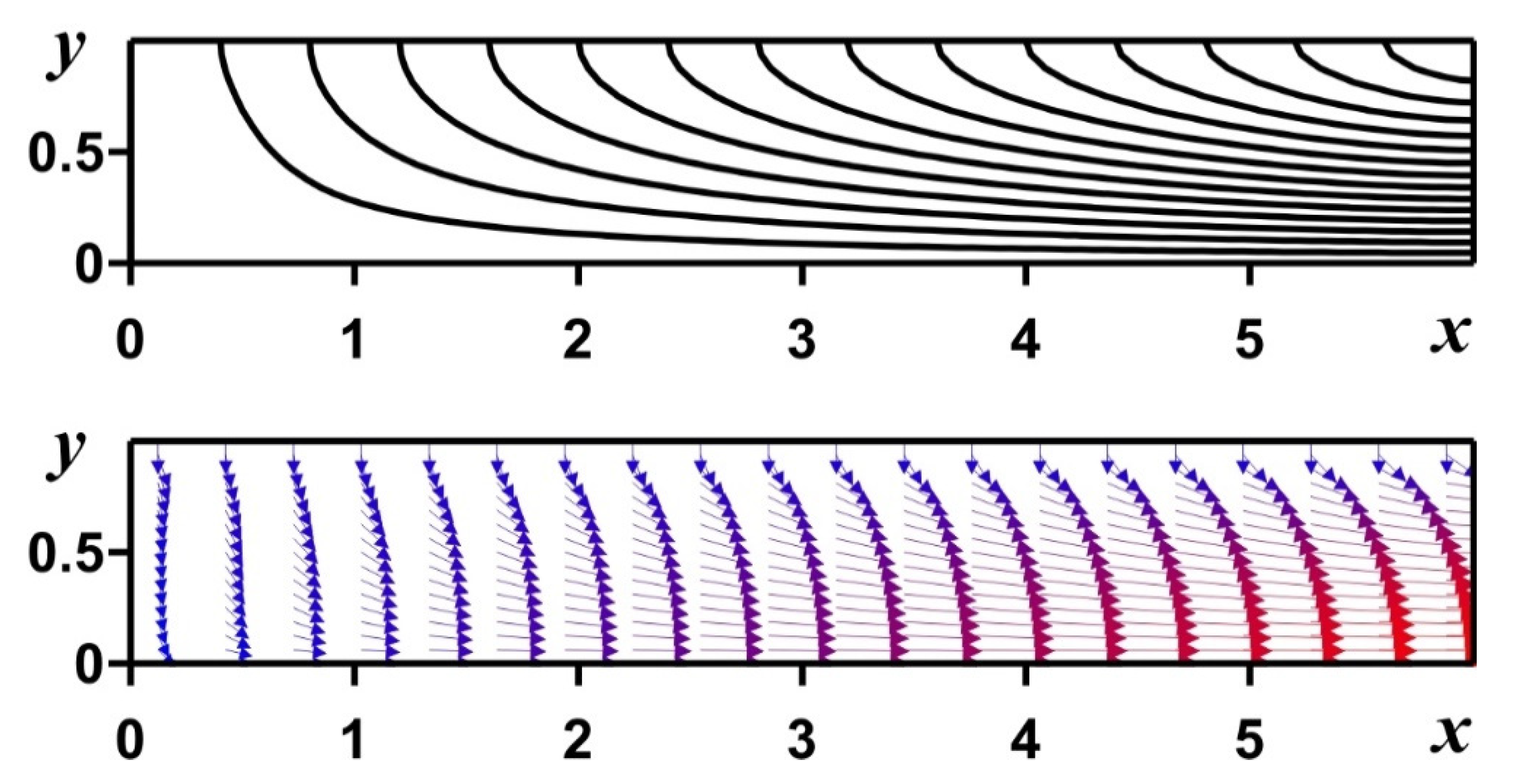
In this section, six analytical methods and two numerical techniques are applied to work out the boundary value challenge. Hence, 2D viscous circulation in a channel bordered by two moved porous plates can be described using the following equations (Figure 12 shows streamlines and velocity field for Re = 5 and α = 1):
f I V ( y ) + α ( y f ( y ) + 3 f ( y ) ) + R e f ( y ) f ( y ) R e f ( y ) f ( y ) = 0
with additional border restrictions
f = 0 , f = 0   at   y = 0
f = 1 , f = 0   at   y = 1
where α is a dimensionless border stretching rate and Re is the penetration Reynolds number.

3.1. Differential Transform Method

Employing the differential conversion from Equation (17), the following form of equation is obtained:
( k + 1 ) ( k + 2 ) ( k + 3 ) ( k + 4 ) F ( k + 4 ) + 3 α ( k + 1 ) ( k + 2 ) F ( k + 2 ) + R e r = 0 k { ( k + 3 r ) ( k + 2 r ) ( k + 1 r ) F ( r ) F ( k + 3 r ) R e ( k + 1 r ) ( k + 2 r ) ( r + 1 ) F ( r + 1 ) F ( k + 2 r ) } = 0
where F(k) denotes the differential transforms of n f(y) and it is defined as
f ( y ) k = 0 m F ( k ) y k
The reduced border restrictions are
F ( 0 ) = 0 , F ( 1 ) = a F ( 2 ) = 0 , F ( 3 ) = b
where a and b are constants. Employing Equation (22) for Equation (20) and by the recurrent technique, all magnitudes of F(k) are calculated. Hence, substituting all F(k) into Equation (21), the series of solutions is defined as below:
f ( y ) k = 0 m F ( k ) y k a y + b y 3 1 5 b α y 5 + 1 840 ( 12 b 2 R e + 8 a b R e α + 24 b α 2 ) y 7 +
Then, by applying the boundary conditions of Equation (19), the constants a and b are calculated. For example, for Re = 1 and α = 1, the values and the solutions are as follows:
a = 1.607412616389382 , b = 0.732958779309001
f ( y ) { + 1.607412616389382 y 0.732958779309001 y 3 + 0.1465917558618002 y 5 0.024487625417451822 y 7 + 0.0040548656166754194 y 9 0.0007243900882554326 y 11 + 0.00014026681559397154 y 13 0.0000287098687570248 y 15
For Re = 1 and α = −1 the values and the solutions are as follows:
a = 1.4233303927298635 , b = 0.34993947766497535
f ( y ) { + 1.4233303927298635 y 0.34993947766497535 y 3 0.06998789553299507 y 5 0.0035052617311971406 y 7 + 0.00008207843066926752 y 9 + 0.00001839421662864927 y 11 + 1.6177454188405032 × 10 6 y 13 + 1.5180717845107875 × 10 7 y 15

3.2. Optimal Homotopy Asymptotic Method

Employing Equation (7), the linear part is defined as
L ( φ ( y , p ) ) = 4 φ ( y , p ) y 4
and the nonlinear part as
N ( φ ( y , p ) ) = α ( y 3 φ ( y , p ) y 3 + 3 2 φ ( y , p ) y 2 ) + R e φ ( y , p ) 3 φ ( y , p ) y 3 R e φ ( y , p ) y 2 φ ( y , p ) y 2
Using the OHAM, a system of equations is constructed.
( 1 p ) 4 φ ( y , p ) y 4 = H ( p ) [ 4 φ ( y , p ) y 4 + α ( y 3 φ ( y , p ) y 3 + 3 2 φ ( y , p ) y 2 ) + R e φ ( y , p ) 3 φ ( y , p ) y 3 R e φ ( y , p ) y 2 φ ( y , p ) y 2 ]
with additional restrictions
φ ( y , p ) = 0 , 2 φ ( y , p ) y 2 = 0   at   y = 0 , φ ( y , p ) = 1 , φ ( y , p ) y = 0   at   y = 1
The f(y) and H(p) are considered as follows:
f ( y ) = f 0 ( y ) + p f 1 ( y ) + p 2 f 2 ( y ) + p 3 f 3 ( y ) , H ( p ) = C 1 p + C 2 p 2 + C 3 p 3
By using f(y) and H(p) from Equation (32) for Equation (30) and some transformation with the help of powers of p-terms, the following solutions can be obtained.
p0: Zero-order problem
f 0 I V = 0 , f 0 ( 0 ) = 0 , f 0 ( 0 ) = 0 , f 0 ( 1 ) = 1 , f 0 ( 1 ) = 0
from which we obtain
f 0 ( y ) = 1 2 ( 3 y y 3 )
p1: First-order problem
f 0 I V C 1 ( ( 3 α R e f 0 ) f 0 + ( α τ + R e f 0 ) f 0 + f 0 I V ) + f 1 I V = 0 , f 1 ( 0 ) = 0 , f 1 ( 0 ) = 0 , f 1 ( 1 ) = 0 , f 1 ( 1 ) = 0
it is obtained that
f 1 ( y ) = 1 280 ( 1 + y ) 2 y ( 1 + y ) 2 ( 2 R e + 28 α + R e y 2 ) C 1
p2: Second-order problem
N ˜ 2 ( ( 3 α R e f 0 ) f 0 + ( α τ + R e f 0 ) f 0 + f 0 I V ) f 1 I V R e f 1 f 0 N ˜ 1 ( ( 3 α R e f 0 ) f 1 + R e f 1 f 0 + ( α τ + R e f 0 ) f 1 + f 1 I V ) + f 2 I V = 0 , f 2 ( 0 ) = 0 , f 2 ( 0 ) = 0 , f 2 ( 1 ) = 0 , f 2 ( 1 ) = 0
and therefore
f 2 ( y ) = 1 3880800 ( 1 + y ) 2 y ( 1 + y ) 2 × (   27720 R e   C 1 388080 α   C 1 13860 R e y 2 C 1 27720 R e C 1 2 2109 R e 2 C 1 2 388080 α   C 1 2 34188 R e α   C 1 2 + 44352 α 2 C 1 2 13860 R e y 2   C 1 2 1590 R e 2 y 2   C 1 2 22792 R e α   y 2   C 1 2 55440 α 2 y 2 C 1 2 1071 R e 2 y 4   C 1 2 3080 R e α   y 4   C 1 2 +   42 R e 2 y 6   C 1 2 27720 R e   C 2 388080   α   C 2 13860 R e y 2   C 2 )
the terms f3(y) are too large to be illustrated graphically. As a result, the final form of f(y) is
f ( y ) f 0 ( y ) + f 1 ( y ) + f 2 ( y ) + f 3 ( y )
Using Equation (14) for f(y) in Equation (17), R(y,C1,C2,C3) and J are defined as follows:
J ( C 1 , C 2 , C 3 ) = 0 1 R 2 ( y , C 1 , C 2 , C 3 ) d y
The constants C1, C2 and C3 are obtained as follows:
J C 1 = J C 2 = J C 3 = 0
For example, for the case of Re = 1 and α = 1, the following 3rd-order approximate solution is determined.
C 1 = 0.91786 04175046 ,   C 2 = 0.01 278230075958 ,   C 3 = 0.00146537709213
f ( y ) f 0 ( y ) + f 1 ( y ) + f 2 ( y ) + f 3 ( y ) = 1.6073181707872106 y 0.73198498827499 y 3 + 0.14375873179501897 y 5 0.020691139639845986 y 7 + 0.0014494859057353551 y 9 + 0.00015553850614010158 y 11 5.901005731747683 × 10 6 y 13 + 1.019264626392781 × 10 7 y 15
and for the case of Re = 1 and α = −1, the following 3rd-order approximate solution is determined.
C 1 = 0.9 3053114640402 ,   C 2 = 0.0 05495179728 ,   C 3 = 0.00062979731698
f ( y ) f 0 ( y ) + f 1 ( y ) + f 2 ( y ) + f 3 ( y ) = 1.4233291737591052 y 0.3499265757711927 y 3 0.07002742585799336 y 5 0.003451123525236634 y 7 + 0.00004662467373035329 y 9 + 0.000027767167732590777 y 11 + 1.453347678263735 × 10 6 y 13 + 1.062061764885037 × 10 7 y 15

3.3. Homotopy Analysis Method

Dinarvand and Rashidi [26] studied this problem by the HAM. Yabushita et al. [23] employed the HAM to solve two coupled nonlinear ODEs by an optimization technique. The optimal characteristics are calculated by minimization of the square residual error defined in the considered physical domain. In the present research, the same as for the OHAM (Equations (14)–(16)), the optimal convergence-control parameter ( ) is found below.
The nth-order approximation of the solution defined using the HAM f(y) is
f ( y ) = f 0 ( y ) + k = 1 n f k ( y )
which depends on the convergence characteristic ( ) . Let
J ( ) = Ω N [ f ( y ) ] 2 d Ω
denote the square residual error of the control relation. The optimal value of ( ) is gained by solving the nonlinear algebraic equation.
d J ( ) d = 0

3.4. Adomian Decomposition Method

In this section, the ADM is employed for the solution of Equation (17) along with the boundary conditions (18) and (19). Let us introduce the fourth-order derivative operator L and inverse operators L−1 as follows:
L = d 4 d η 4 ( ) ,   L 1 ( ) = 0 η 0 η 0 η 0 η ( · ) d η d η d η d η
Thus Equation (17) becomes
L 1 ( L f ) = α L 1 ( y f ( y ) 3 L 1 f ( y ) ) R e L 1 ( f ( y ) f ( y ) ) + R e L 1 ( f ( y ) f ( y ) )
The function f(η) is
f ( η ) = m = 0 f m
The remaining terms of (17) can be expressed as
m = 0 A m = f ,   m = 0 B m = f ,   m = 0 C m = f   f ,   m = 0 D m = f   f
Here, a recursive formula is used to find all the components. The exact solutions of (17) are given by
f ( η ) = lim m = 0 f m
Therefore, the RHSs of Equation (50) are given by
L 1 ( L f ) = f ( η ) f ( 0 ) f ( 0 ) η 1 2 ! f ( 0 ) η 2 1 3 ! f ( 0 ) η 3
From (18), (19) and invoking the border restrictions
f ( 0 ) = 0 , f ( 0 ) = p , f ( 0 ) = 0 , f ( 0 ) = q
The solutions of Equation (50) can therefore be written as
f ( y ) = p y + 1 3 ! y 3 α L 1 ( y f ( y ) 3 L 1 f ( y ) ) R e L 1 ( f ( y ) f ( y ) ) + R e L 1 ( f ( y ) f ( y ) )
The unknowns p, q should be evaluated numerically. Utilizing Equation (55), the initial imposed solutions along with higher-order recursive solutions are
f 0 ( η ) = p y + 1 6 q η 3
f m + 1 ( y ) = α L 1 ( y m = 0 A m 3 L 1 ( m = 0 B m ) ) R e L 1 ( m = 0 C m ) + R e L 1 ( m = 0 D m )
Employing m = 0, 1, 2 in Equation (58) with the help of Equation (57), we can generate the solutions of Equation (17) as follows
For Re = 1, α = 1, p = 1.607455717997487, q = −4.398102771374896 and
f 0 ( y ) = { 1.6074557179974873211136809914024 y 0.73301713541899167954814705202201 y 3 }
f 1 ( y ) = { 0.1466034270837983359096294104044 y 5 + 0.007675916011683776946257081725633 y 7 }
f 2 ( y ) = { 0.0209433467262569051299470586292 y 7 0.00085287955685375299402856463618145 y 9 + 0.000108548307235932199239999135514 y 11 + 0.0000052462265422855138880469138211013 y 13 + 0.0000001510761195344189254895445928002 y 15 }
f 3 ( y ) = { 0.000000000000000012694101164392678338056024603325 y 31 + 0.00000000000000086762949995289280758585817353344 y 29 + 0.000000000000029731520143652335165850205073171 y 27 + 0.00000000000093736065343352189357406674780089 y 25 + 0.000000000022177051578771010688671916457026 y 23 + 0.000000000034676509888662690170844729029353 y 21 + 0.00000000034398042251646165604396405969283 y 19 + 0.000000043648911424223850740860729584406 y 17 + 0.00000077492790255587811387483310432703 y 15 0.0000083498697873793999415383950395387 y 13 + 0.000077534505168522999457142239652859 y 11 + 0.0023270385251396561255496731810222 y 9 }
Therefore, the solution can be expressed as
f ( y ) = { 1.6074557143337926401471804638277 y 0.73301712856248268934677980723791 y 3 + 0.14660342571249653786935596144758 y 5 0.013267430662271115762682676828017 y 7 + 0.0014741589624745684180758529808908 y 9 + 0.00018608280892328563646953151048126 y 11 0.0000031036432361043054169820277481217 y 13 + 0.000000926004005212156828355314473975 y 15 + 0.000000043648910282497716362697136445564 y 17 + 0.00000000034398040233136267872854810633553 y 19 + 0.000000000034676508591231637192383384345989 y 21 + 0.000000000022177050655663200110526485898967 y 23 + 0.00000000000093736060854598511032723057595758 y 25 + 0.000000000000029731518475032976571409343222361 y 27 + 0.00000000000000086762944314335441420517237892509 y 29 + 0.000000000000000012694100214486197835630960202222 y 31 + }

3.5. Variation Iteration Method

The illustration of the basic concept of the approximate analytical solution, i.e., the variation iteration method (VIM) is as follows.
Let us analyze the standard view of the nonlinear differential relation as
L u + N u = g ( t )
The linear function is represented as L, the nonlinear part is N and g(t) is an inhomogeneous part. The construction of the correct operator employing the VIM is presented as
u n + 1 ( t ) = u 0 ( t ) + 0 t λ ( ξ ) { L u n ( ξ ) + N u n ( ξ ) ¯ g ( ξ ) } d ξ
Here u 0 ( t ) is the initial assumed solution obtained using the initial conditions and the suitable choice of unknown initial conditions, u n ( ξ ) ¯ is the restricted function and λ ( ξ ) is the Lagrangian multiplier obtained using the Wronskian conditions.
Employing the aforesaid methodology, the present problem can be expressed as
f n + 1 ( y ) = f 0 ( y ) + 0 y λ ( ξ ) { f n I V ( ξ ) + α ( y f n ( ξ ) + 3 f n 2 ( ξ ) ) + R e ( f n ( ξ ) f n ( ξ ) f n ( ξ ) f n ( ξ ) ) ¯ } d ξ
The Lagrangian multiplier is
λ 1 = 1 3 ! ( ξ y ) 3
With the initial choice of
f ( 0 ) = p = 1.607455717997487   and   f ( 0 ) = q = 4.398102771374896
the initial approximate solutions along with the final iterative solution are presented.
f 0 ( y ) = 1.6074557179974873211136809914024 y 0.73301713541899167954814705202201 y 3
f 1 ( y ) = { 1.6074557143337926401471804638277 y 0.73301712856248268934677980723791 y 3 + 0.14660342571249653786935596144757 y 5 + 0.0076759158680855325043681748073517 y 7 }
f 2 ( y ) = { + 1.6074557143337926401471804638277 y 0.73301712856248268934677980723791 y 3 + 0.14660342571249653786935596144758 y 5 0.024489264681435983644897385698975 y 7 0.0023912421276245363169726643489703 y 9 + 0.00014264877677319694670045689130833 y 11 + 0.000005246226395068768014343104132445 y 13 + 0.0000001510761138818648052282723601165 y 15 }
f ( y ) = { + 1.6074557143337926401471804638277 y 0.73301712856248268934677980723791 y 3 + 0.14660342571249653786935596144758 y 5 0.024489264681435983644897385698981 y 7 + 0.0040551170043726611238632715930647 y 9 + 0.00042680238907571681642647340812367 y 11 0.000063984600147030603517386683748288 y 13 + 0.0000029583457301427006366300521381065 y 15 + 0.00000012929372864415645394815279192283 y 17 + 0.0000000039645266013200060992361776978167 y 19 0.000000000648366750674015784910314949795 y 21 + 0.000000000028604802064534090334445320171667 y 23 + 0.00000000000139872973728563581077768259875 y 25 + 0.000000000000032666998091001325672803509771667 y 27 + 0.00000000000000086762944314335441420517237891667 y 29 + 0.000000000000000012694100214486197835630960202333 y 31 + }

3.6. Reproducing Kernel Hilbert Space Method

The reproducing kernel Hilbert space method (RKHSM) without the Gram–Schmidt orthogonalization process, is analyzed in this manuscript. Some applications of the RKHSM to solve various differential equations are presented in [25,26,27,28]. We consider the reproducing kernel space W5[0,1] for Equations (17)–(19), such that f (4)(y) is absolutely continuous and f (5)(y) ∈ L2[0,1] should satisfied the following conditions f ( 0 ) = 0 , f ( 0 ) = 0   and   f ( 1 ) = 0 ,   f ( 1 ) = 0 . The inner product and norm are as follows:
f ( y ) , g ( y ) W 5 = i = 0 4 f ( i ) ( a ) · g ( i ) ( a ) + a b f ( 5 ) ( y ) g ( 5 ) ( y ) d y
for all f, gW5[0,1] and we analyze the reproducing kernel operator for space W5[0,1] in the form [24]
R x ( y ) = { R ( y , x ) R ( x , y )
After homogenization of Equations (17)–(19) with function A ( x ) = 3 x 3 x 2 + x 3 we obtain
L ( f ( y ) ) = 6 R e f ( y ) + 6 R e f ( y ) 6 R e y f ( y ) 3 R e f ( y ) + 6 R e y f ( y ) 3 R e y 2 f ( y ) + 3 α f ( y ) + 3 R e y f ( y ) 3 R e y 2 f ( y ) + R e y 3 f ( y ) + y α f ( y ) + f ( 4 ) ( y )
Analyze N ( f ( y ) ) = R e f ( y ) f ( y ) + R e f ( y ) f ( y ) and F ( y ) = 18 R e + 36 R e y 36 R e y 2 + 12 R e y 3 + 18 α 24 α y on [0,1] where L(f(y)) is a linear function, N(f(y)) is a non-linear function and F(y) is a right-hand-side function. It is not difficult to understand that L is a bordered linear function. Assume L:W5[0,1]→W1[0,1], and ry(x) is a reproducing kernel operator for W1[0,1]. We choose a dense set { x i } i = 1 in [0,1] and define φ i ( y ) = r x ( y ) x = x i and ψ i ( y ) = L * φ i ( y ) where L* is an adjoint function of L and L–1 exists. This can be proved by ξ i ( y ) = R x ( y ) x = x i , which are a complete function system in W5[0,1]. In this method we assume
f ( y ) = i = 1 c i ξ i ( y )
is an exact solution of Equation (17) where { x i } i = 1 are dense points on [0,1]. Consider an approximate solution for Equation (17) as f n ( y ) = i = 1 c i ξ i ( y ) , where n is the number of collocation points on [0,1] and ξ i ( y ) = R x ( y ) x = x i . One can obtain ci by solving the following iterative system of algebraic equations
L [ f n [ l ] ( y j ) ] = F ( y j ) + N ( f n [ l 1 ] ( y j ) ) ,   j = 1 , 2 , , n ,   l = 1 , 2 , , M
where f n [ 0 ] 0 .

3.7. Finite Difference Method for ODEs

The main idea of the finite difference method is to approximate the derivatives in ODEs using the finite differences, taking into account the Taylor series and after that solving the obtained system of equations. For this purpose, the uniform mesh is introduced as a first step of this technique. As a result, the numerical solution of the boundary value problem (17)–(19) has been performed using the finite difference method and a uniform mesh. The uniform mesh has been introduced as follows:
y i = i · h ,   i = 0 , N ¯ ; h = 1 / N
Derivatives presented in Equation (17) have been approximated using the following central differences of second-order accuracy
f ( y i ) = f ( y i + 1 ) f ( y i 1 ) 2 h + O ( h 2 )
f ( y i ) = f ( y i + 1 ) 2 f ( y i ) + f ( y i 1 ) h 2 + O ( h 2 )
f ( y i ) = f ( y i + 2 ) 2 f ( y i + 1 ) + 2 f ( y i 1 ) f ( y i 2 ) 2 h 3 + O ( h 2 )
f I V ( y i ) = f ( y i + 2 ) 4 f ( y i + 1 ) + 6 f ( y i ) 4 f ( y i 1 ) + f ( y i 2 ) h 4 + O ( h 2 )
Using these mentioned central differences, Equation (17) has been reduced to the set of equations that was determined by the successive over-relaxation procedure as follows:
f ˜ i [ 6 h 4 6 α h 2 + R e f i + 2 s 2 f i + 1 s + 2 f i 1 s + 1 f i 2 s + 1 2 h 3 + R e f i + 1 s f i 1 s + 1 h 3 ] = R e 2 h 3 ( f i + 1 s f i 1 s + 1 ) ( f i + 1 s + f i 1 s + 1 ) α y i 2 h 3 ( f i + 2 s 2 f i + 1 s + 2 f i 1 s + 1 f i 2 s + 1 ) 3 α h 2 ( f i + 1 s + f i 1 s + 1 ) f i + 2 s 4 f i + 1 s 4 f i 1 s + 1 + f i 2 s + 1 h 4 , f i s + 1 = f i s + κ ( f ˜ i f i s ) , 1 < κ < 2
The convergence condition used is
| f i s + 1 f i s | ε
It should be noted that boundary conditions (18) and (19) have been approximated as follows:
f 0 = 0 , f 1 = 2 f 0 + 4 f 2 f 3 5 , f N 1 = 3 f N + f N 2 4 , f N = 1
The mesh sensitivity analysis has been carried out for this technique using two different uniform meshes of 21 nodes and 40 nodes. Table 1, Table 2, Table 3 and Table 4 show that a mesh of 21 nodes is enough for this analysis, because the differences between these two grids are too small.

3.8. Finite Difference Method for PDE

It should be noted that the formulated boundary value problem (17)–(19) for ODEs was obtained using the original Navier–Stokes equations with appropriate initial and boundary conditions that were written for laminar, isothermal and incompressible fluid circulation between two horizontal permeable plates.
Therefore, the finite difference method was employed for the numerical solution to the following problem:
u ¯ x ¯ + v ¯ y ¯ = 0
u ¯ t + u ¯ u ¯ x ¯ + v ¯ u ¯ y ¯ = 1 ρ p ¯ x ¯ + μ ρ ( 2 u ¯ x ¯ 2 + 2 u ¯ y ¯ 2 )
v ¯ t + u ¯ v ¯ x ¯ + v ¯ v ¯ y ¯ = 1 ρ p ¯ y ¯ + μ ρ ( 2 v ¯ x ¯ 2 + 2 v ¯ y ¯ 2 )
with additional restrictions that were written as
t = 0 : u ¯ = v ¯ = 0
t > 0 : u ¯ = 0 , v ¯ = V w   at   y ¯ = a ( t ) u ¯ y ¯ = 0 , v ¯ = 0   at   y ¯ = 0 u ¯ = 0   at   x ¯ = 0
These formulated boundary value problems for partial differential equations were reduced using the stream function and vorticity that were determined as
u ¯ = ψ ¯ y ¯ , v ¯ = ψ ¯ x ¯ , ω ¯ = v ¯ x ¯ u ¯ y ¯
Taking into account these new functions, governing Equations (81)–(83) were rewritten as
2 ψ ¯ x ¯ 2 + 2 ψ ¯ y ¯ 2 = ω ¯
ω ¯ t + ψ ¯ y ¯ ω ¯ x ¯ ψ ¯ x ¯ ω ¯ y ¯ = μ ρ ( 2 ω ¯ x ¯ 2 + 2 ω ¯ y ¯ 2 )
Additional restrictions (84) and (85) were formulated as
t = 0 : ψ ¯ = ω ¯ = 0
t > 0 : ψ ¯ = V w x ¯ , ω ¯ = 2 ψ ¯ y ¯ 2   at   y ¯ = a ( t ) ψ ¯ = 0 , ω ¯ = 0   at   y ¯ = 0 ψ ¯ = 0 , ω ¯ = 2 ψ ¯ x ¯ 2   at   x ¯ = 0
Taking into account the following dimensionless parameters
x = x ¯ a ( t ) , y = y ¯ a ( t ) , u = u ¯ a ˙ ( t ) , v = v ¯ a ˙ ( t ) , τ = t a ˙ ( t ) a ( t ) , ψ = ψ ¯ a ( t ) a ˙ ( t ) , ω = ω ¯ a ( t ) a ˙ ( t )
Using these parameters, the non-dimensional governing equations are
2 ψ x 2 + 2 ψ y 2 = ω
ω τ + ψ y ω x ψ x ω y = 1 α ( 2 ω x 2 + 2 ω y 2 )
Non-dimensional restrictions are
τ = 0 : ψ = ω = 0
τ > 0 : ψ = R e α x , ω = 2 ψ y 2   at   y = 1 ψ = 0 , ω = 0   at   y = 0 ψ = 0 , ω = 2 ψ x 2   at   x = 0
Here α = ρ · a · a ˙ μ and R e = ρ · a · V w μ .
These formulated boundary-value problems (92)–(95) were solved by the finite difference method with second-order accuracy for a uniform mesh. The employed schemes of the second-order were used for the diffusive part and convective part, where the first-order approximation was applied for the unsteady term. The convective terms were discretized by means of the monotonic Samarskii procedure and the central difference scheme was used for diffusive terms.
The solution of Equation (93) was obtained using the Samarskii locally one-dimensional technique with an additional time level:
ω i , j n + 1 / 2 ω i , j n Δ τ + u i , j n + 1 ω i + 1 , j n + 1 / 2 ω i 1 , j n + 1 / 2 2 h x | u i , j n + 1 | ω i + 1 , j n + 1 / 2 2 ω i , j n + 1 / 2 + ω i 1 , j n + 1 / 2 2 h x = 1 α ( 1 + | u i , j n + 1 | α h x 2 ) 1 ω i + 1 , j n + 1 / 2 2 ω i , j n + 1 / 2 + ω i 1 , j n + 1 / 2 h x 2
ω i , j n + 1 ω i , j n + 1 / 2 Δ τ + v i , j n + 1 ω i , j + 1 n + 1 ω i , j 1 n + 1 2 h y | v i , j n + 1 | ω i , j + 1 n + 1 2 ω i , j n + 1 + ω i , j 1 n + 1 2 h y = 1 α ( 1 + | v i , j n + 1 | α h y 2 ) 1 ω i , j + 1 n + 1 2 ω i , j n + 1 + ω i , j 1 n + 1 h y 2
where i and j are the indexes for the nodes over the x and y coordinates, n is the time zone index, Δτ is the time step, and hx and hy are the grid steps for the x and y coordinates. At the final level of solution, the discretized Equations (96) and (97) were solved by the Thomas method.
The difference relation for the stream function was worked out employing the successive over-relaxation procedure as follows
{ ψ ˜ i , j = h y 2 ( ψ i + 1 , j k + ψ i 1 , j k + 1 ) 2 ( h x 2 + h y 2 ) + h x 2 ( ψ i , j + 1 k + ψ i , j 1 k + 1 ) 2 ( h x 2 + h y 2 ) + h x 2 h y 2 ω i , j 2 ( h x 2 + h y 2 ) ψ i , j k + 1 = ψ i , j k + κ ( ψ ˜ i , j ψ i , j k )
where k is an index of iterations and κ is the relaxation parameter.
It should be noted that this formulated finite difference technique has previously been validated using the mesh sensitivity analysis and some model problems.

4. Results and Discussion

The program code was developed by MATHEMATICA and the simulations were defined using a PC with 756 MB of RAM and 2.40 GHz CPU. In the case of the FDM for ODEs and PDEs the computational code was developed using C++ programming language. Table 1, Table 2, Table 3 and Table 4 show a comparison of the five analytical methods and the FDM and show the absolute error for computational results and the analytical solutions. We have deliberately provided many digits for comparison in the tables to better show the accuracy of each method. In fact, few digits cannot show the accuracy clearly. The numerical solution, the OHAM and HAM by 3rd-order approximate solution and the DTM (m = 10) by 10th-order approximate solution for the case of Re =5 and α = 1 are presented in Table 1. In addition, for the same case we compared the computational results with the OHAM and HAM by 4th-order approximate solution and the DTM (m = 20) by 20th-order approximate solution. Numerical results obtained by the OHAM and HAM (5th-order) and the DTM (m = 30) for the same case are shown in Table 3. For all approaches, the absolute error diminishes quickly with the order of approximation increment. Table 4 compares the numerical simulation results with the ADM and VIM. In the case of the FDM for ODEs, it should be highlighted that the uniform mesh of 21 nodes that was used was enough for obtaining the convergent result.
From Table 1, Table 2, Table 3 and Table 4 it can be highlighted that the OHAM approximate relation defined in this research allows us to obtain better outcomes than the DTM and HAM approximations, and the HAM approximate expression is more accurate than the DTM approximation for this problem. In addition, the ADM is more accurate than the VIM.
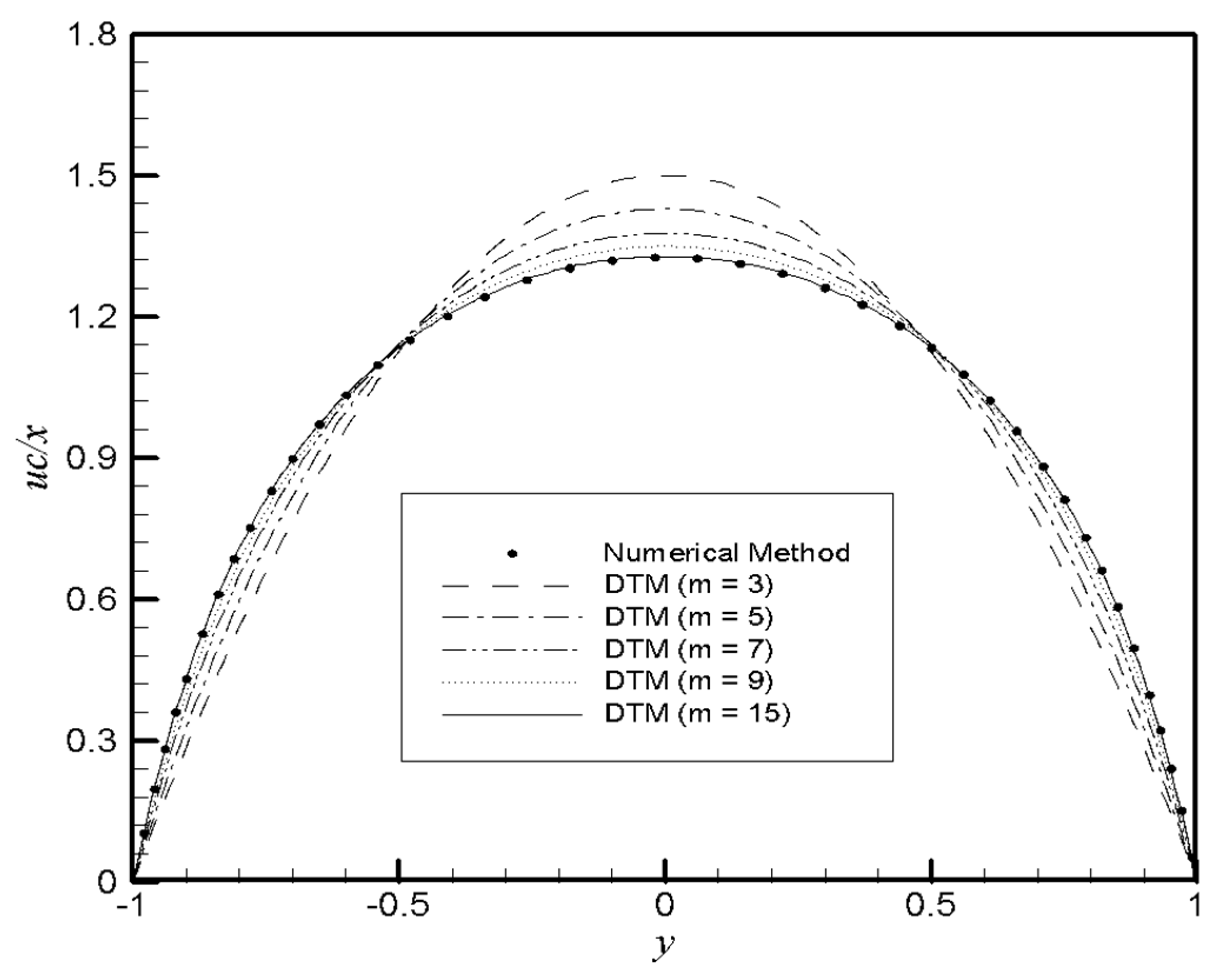
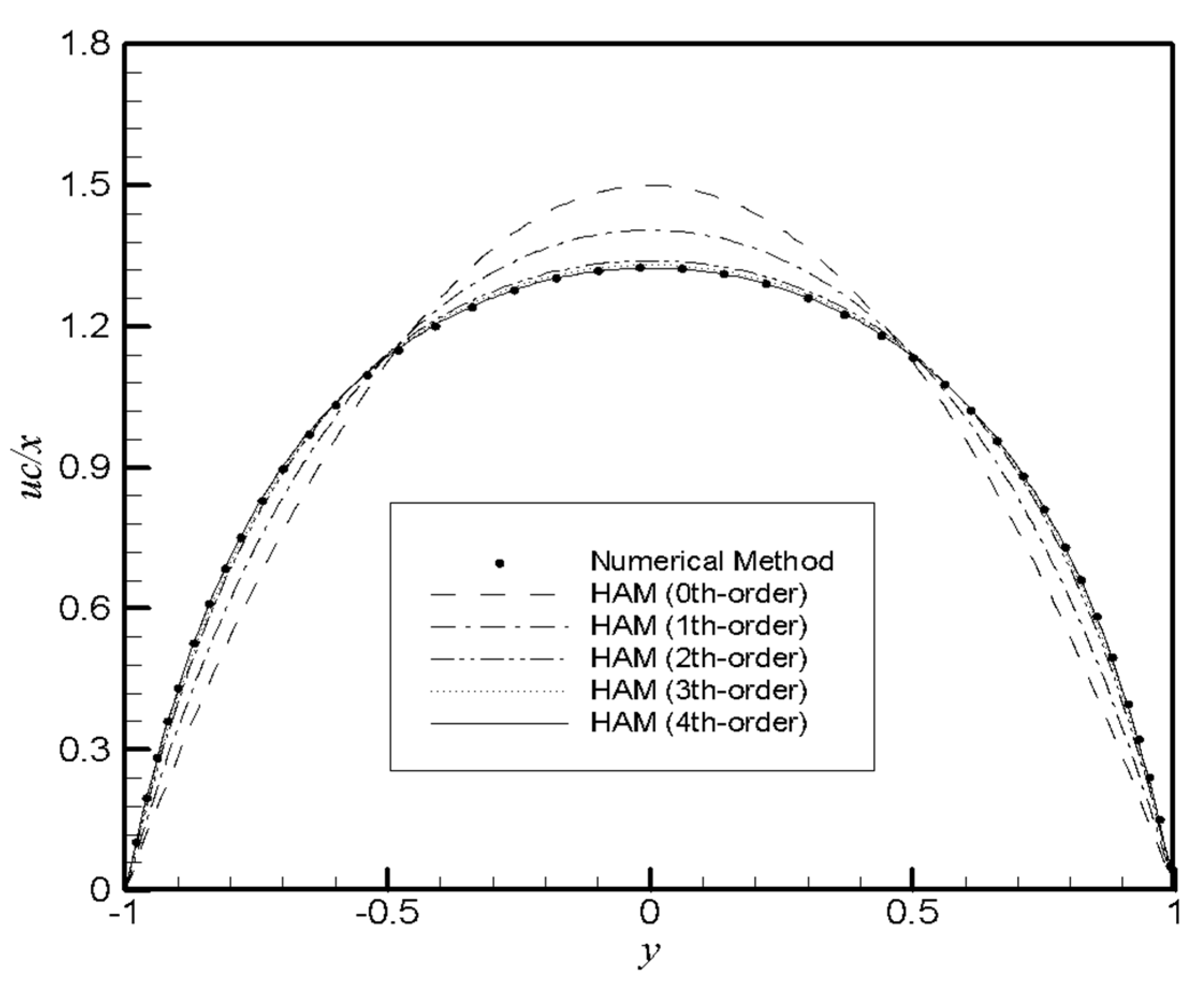
The function uc/x (f′(y)) obtained by the OHAM, HAM and the DTM at various orders of approximation for the case of contraction combined with suction (Re = −5 and α = −1) are compared with the computational outcomes in Figure 1, Figure 2 and Figure 3.
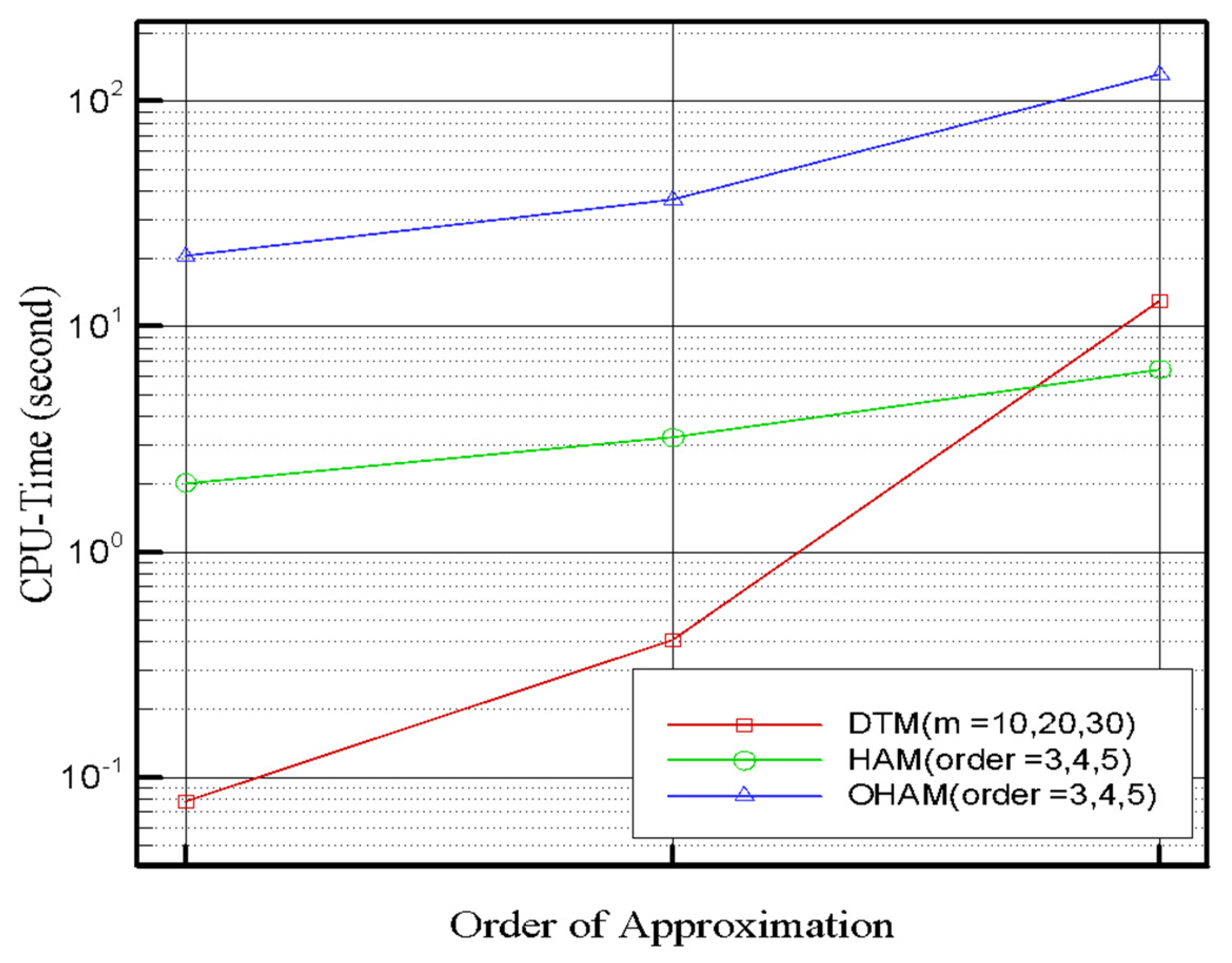
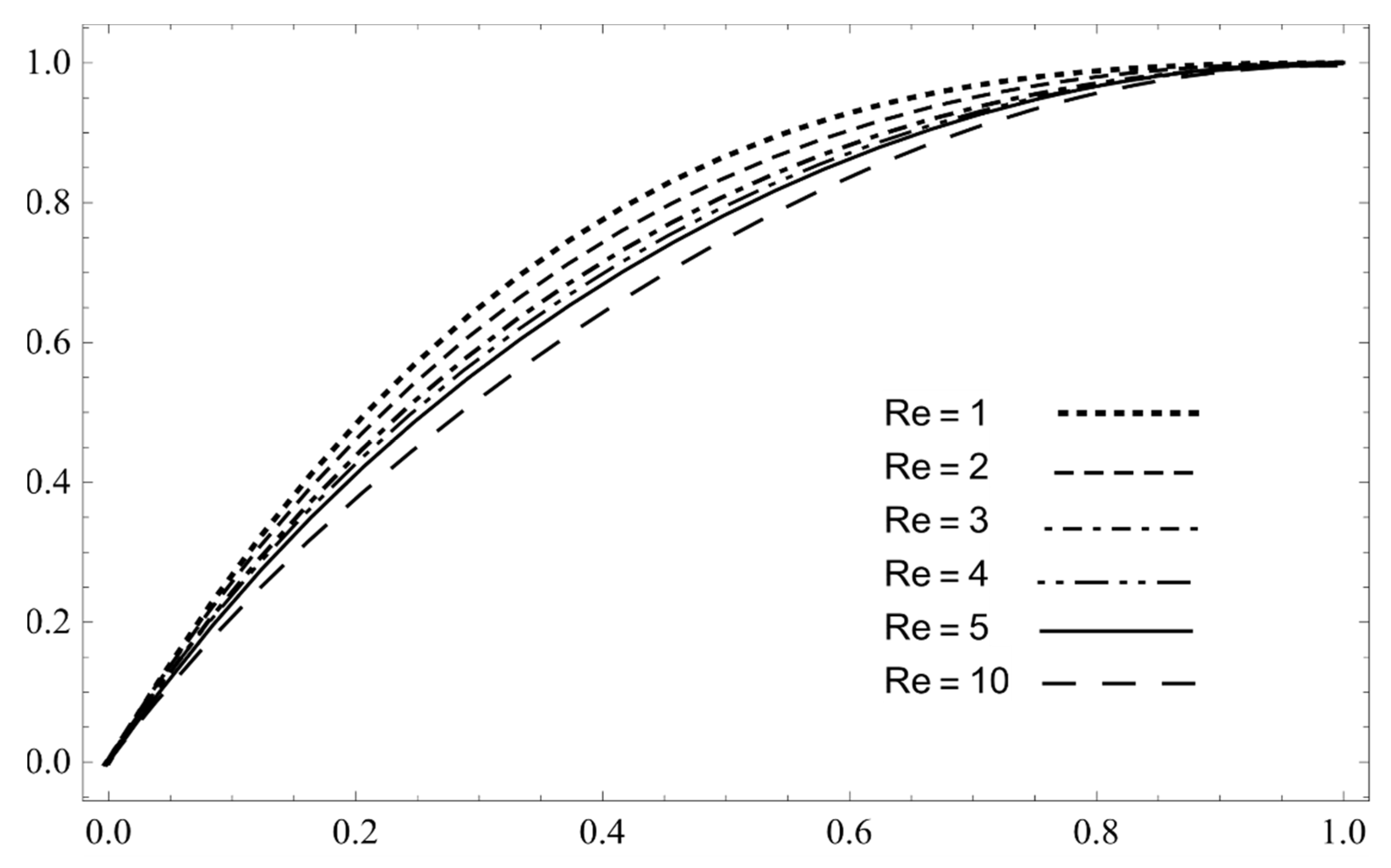
The comparison of CPU time given by the OHAM, DTM and HAM at various orders of approximation for the case of Re = 5 and α = 1 is given in Table 5 and Figure 4. Since the DTM method uses the transformed function to convert the differential equations to algebraic equations, it is easier to calculate than the HAM and OHAM. In the other two methods, the differential equations are solved in each iteration. From Table 5 and Figure 4, it is inferred that the OHAM has more unknown parameters and takes more CPU time to converge, especially for high-order approximations.
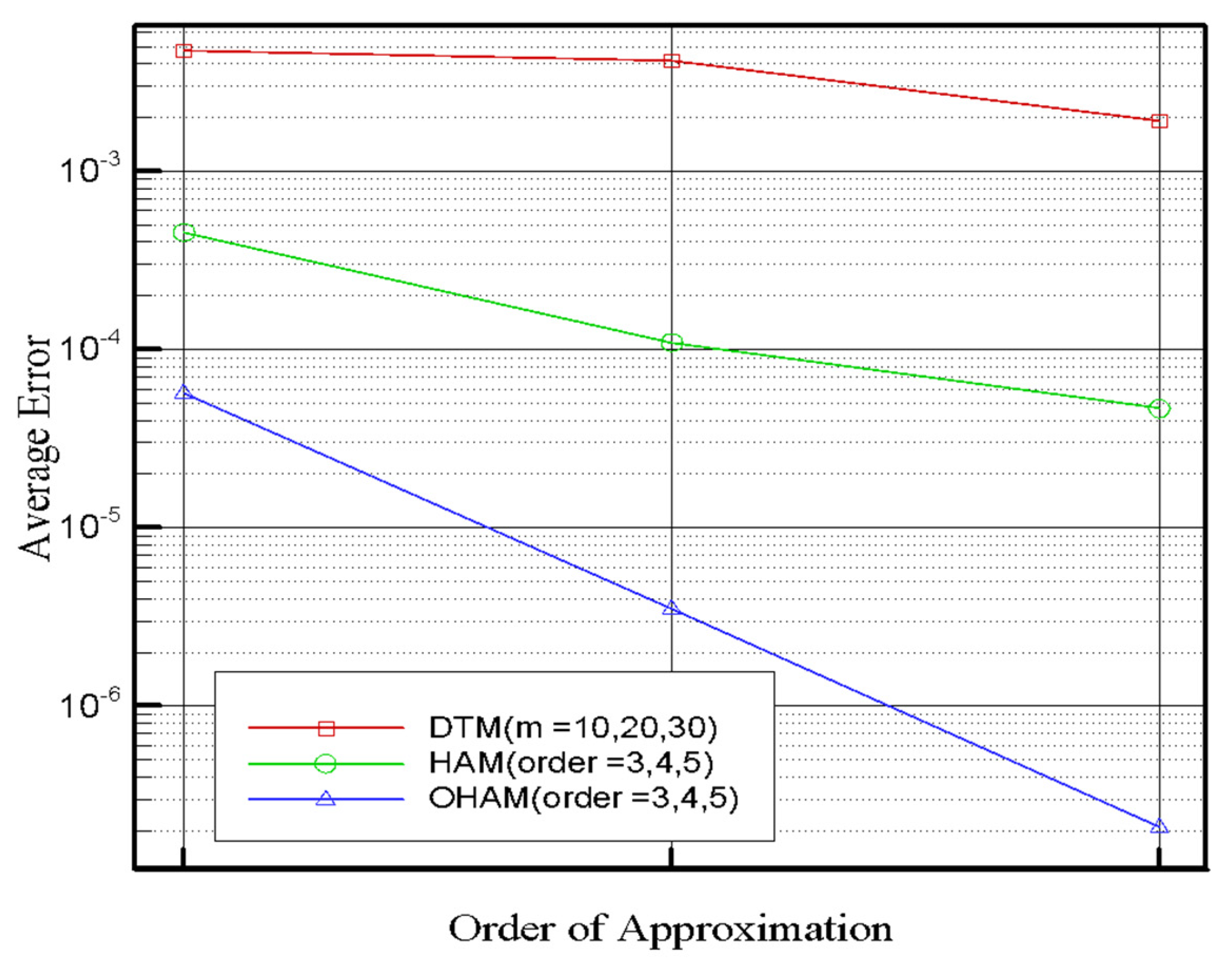
The average error Equation (73) for K = 100 obtained by different approaches at different orders of approximation for the case of (Re = 5 and α = 1) is shown in Figure 5. Figure 5 illustrates that the accuracy of the solution obtained by the OHAM is better than the HAM and DTM in all orders of approximation (3rd order OHAM is better that 3rd order HAM and DTM with 10 terms of polynomials, …).
Error = 1 K i = 0 K | f N u m e r i c a l ( y = i K ) f A n a l y t i c a l ( y = i K ) |
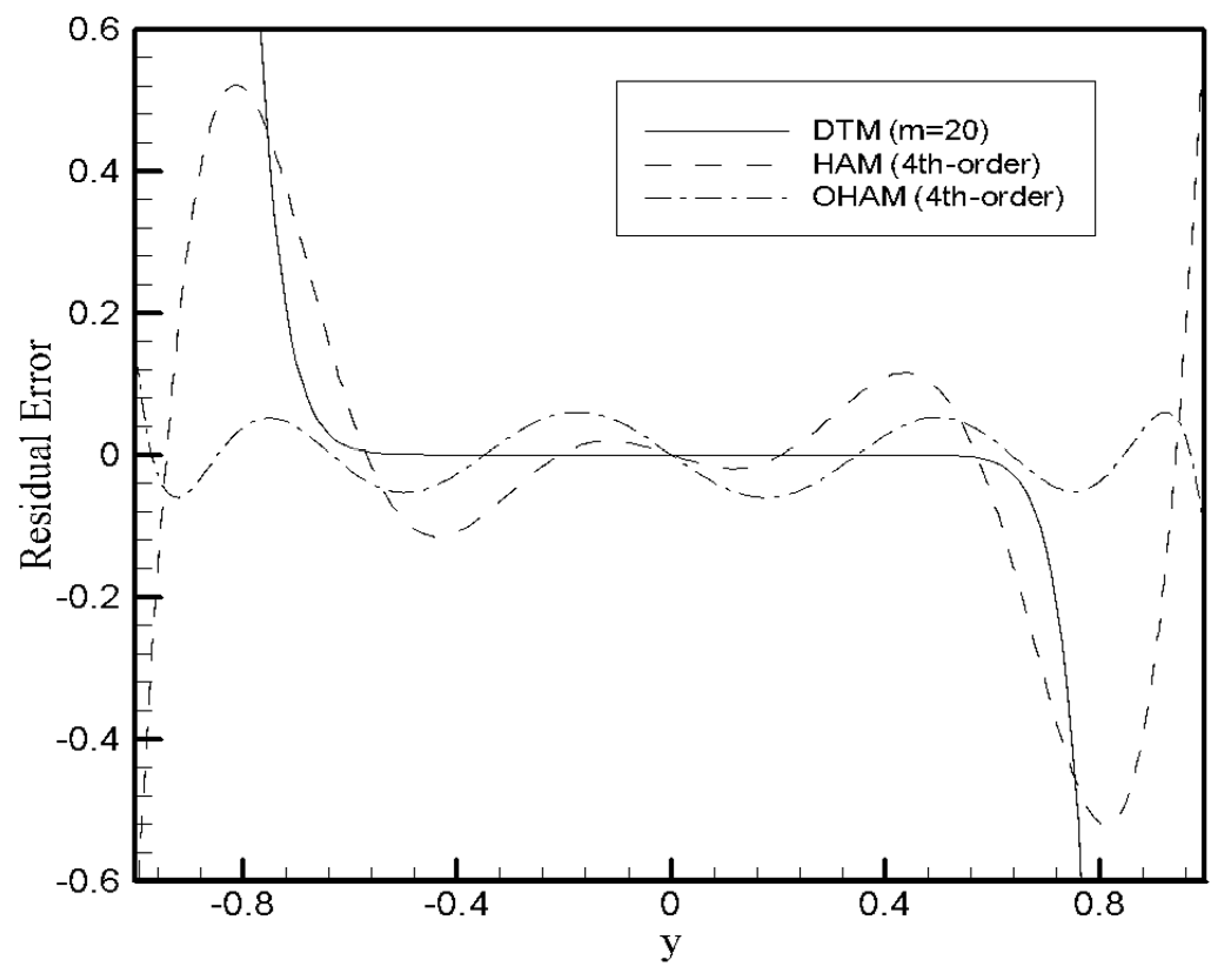
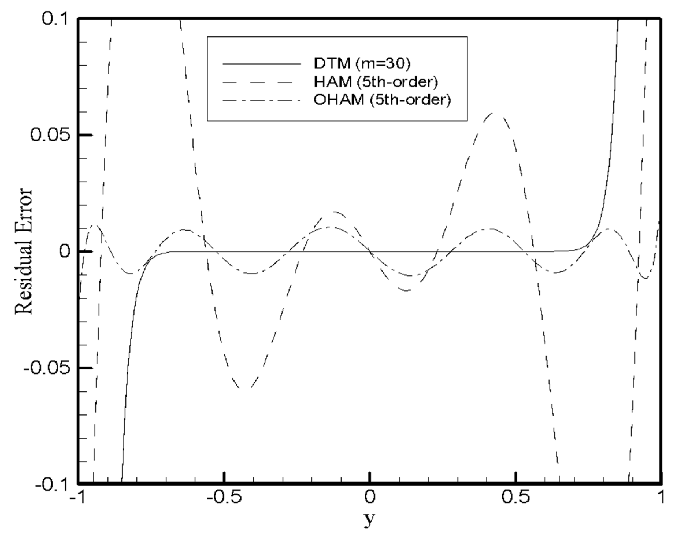
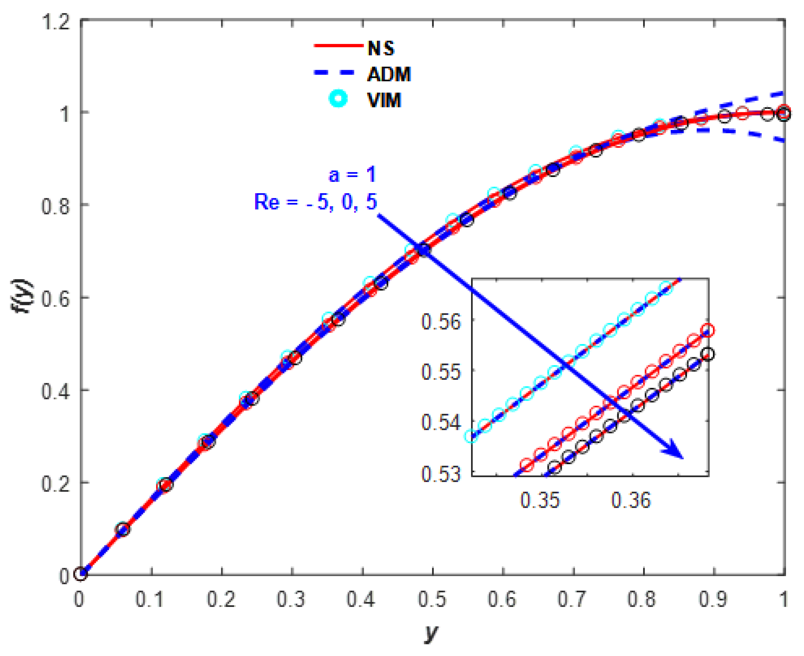
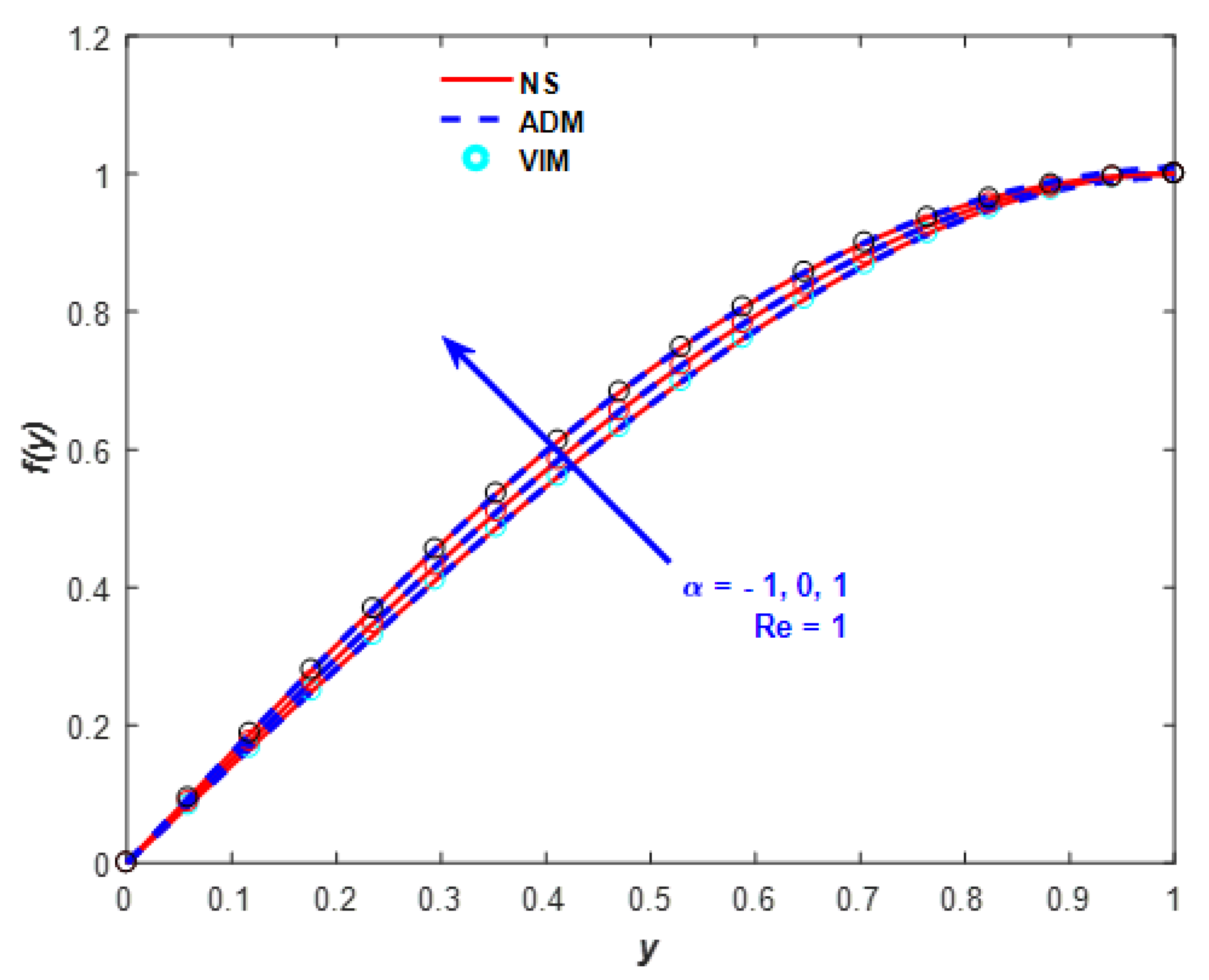
Substituting the approximate solution into Equation (17) yields the residual error. In Figure 6 and Figure 7, we present the residual error of different approaches for the case of Re = 5, α = 1. Figure 6 presents the residual error for the OHAM and HAM by 4th-order approximate solution and the DTM by m = 20, and Figure 7 presents the residual error for the OHAM and HAM by 5th-order approximate solution and the DTM by 30th-order approximate solution (with a polynomial by 30 terms). It can be seen from Figure 6 and Figure 7 that the accuracy of the solution defined using the OHAM is very good in both cases. In addition, the residual error obtained by the DTM increases as y increases. This is because in the DTM the Taylor expansion is used about (y = 0). For the case of the ADM and VIM solutions, Figure 8 and Figure 9 show the f(y) solution with various Re and α. The ADM shows different results in larger y and especially in high Reynolds numbers.
In the RKHSM, the residual error (RError) is calculated using
RError = i = 1 n [ L ( f n ( y i ) ) + N ( f n ( y i ) ) F ( y i ) ] 2 / n
in Table 6, and we consider M = 10 and n = 40 for Figure 10 and Figure 11. The obtained results show the high accuracy of this method for large Reynolds numbers.
Figure 12 shows the streamlines and velocity field for Re = 5 and α = 1 that were obtained employing the FDM for PDEs.

5. Conclusions

In this study, different analytical/numerical methods were proposed to solve 2D viscous fluid motion between expanding/contracting horizontal permeable plates. The results were compared with the HAM, ADM, VIM, … and numerical results (shooting procedure combined with a Runge–Kutta fourth-order integration technique and the FDM), and obtained satisfactory outcomes. The result can be further improved by increasing the order of approximation. These approaches are simple to use because, unlike other numerical and approximate methods, they do not require linearization, discretization or perturbation. The proposed procedures are also valid for nonlinear differential equations. The OHAM and HAM provide a convenient method to manage the convergence and the user can easily adjust the desired convergence regions. It is clear that the OHAM has a high accuracy compared to the DTM. However, having many unknown constants is time-consuming when simulating the square residual errors for high-order approximation, as shown in Figure 4 and Table 5. The HAM uses less CPU time compared to the OHAM, which first has the unique convergence managing characteristic ( ) as an unknown and then gives its effective magnitude by minimizing the square residual error.

Author Contributions

All sections related to DTM, HAM, OHAM are carried out by M.M.R., E.E., M.S., F.R. FDM is done M.A.S.; ADM and VIM is done by S.M., P.K.P.; RKHSM is studied by S.A., H.S. All authors have read and agreed to the published version of the manuscript.

Funding

This research received no external funding.

Conflicts of Interest

The authors declare no conflict of interest.

References

  1. Nayfeh, A.H. Introduction to Perturbation Technique; Wiley: New York, NY, USA, 1981. [Google Scholar]
  2. Rand, R.H.; Armbruster, D. Perturbation Methods, Bifurcation Theory and Computer Algebraic; Springer: New York, NY, USA, 1987. [Google Scholar]
  3. Bouchon, F.; Clain, S.; Touzani, R. A perturbation method for the numerical solution of the Bernoulli problem. J. Comput. Math. 2008, 26, 23–36. [Google Scholar]
  4. Adomian, G. New approach to nonlinear partial differential equations. J. Math. Anal. Appl. 1984, 102, 420–434. [Google Scholar] [CrossRef] [Green Version]
  5. Adomian, G. A Review of the Decomposition Method in Applied Mathematics. J. Math. Anal. Appl. 1988, 135, 501–544. [Google Scholar] [CrossRef] [Green Version]
  6. Adomian, G. Solving Frontier Problems of Physics: The Decomposition Method; Kluwer Academic Publishers: Boston, MA, USA, 1994. [Google Scholar]
  7. He, J.H. A new approach to non-linear partial differential equations. Commun. Nonlinear Sci. Numer. Simul. 1997, 2, 4. [Google Scholar] [CrossRef]
  8. He, J.H. Homotopy Perturbation Technique. Comput. Methods Appl. Mech. Eng. 1999, 178, 257–262. [Google Scholar] [CrossRef]
  9. Zhou, J.K. Differential Transformation and Its Applications for Electrical Circuits; Huazhong University Press: Wuhan, China, 1986. (In Chinese) [Google Scholar]
  10. Pukhov, G.E. Computational structure for solving differential equations by Taylor transformations. Cybern. Syst. Anal. 1978, 14, 383–390. [Google Scholar] [CrossRef]
  11. Chen, C.K.; Ho, S.H. Solving partial differential equations by two dimensional differential transform method. Appl. Math. Comput. 1999, 106, 171–179. [Google Scholar]
  12. Ayaz, F. On the two-dimensional differential transform method. Appl. Math. Comput. 2003, 143, 361–374. [Google Scholar] [CrossRef]
  13. Ayaz, F. Solutions of the systems of differential equations by differential transform method. Appl. Math. Comput. 2004, 147, 547–567. [Google Scholar] [CrossRef]
  14. Rashidi, M.M.; Erfani, E. New analytical method for solving Burgers’ and nonlinear heat transfer equations and comparison with HAM. Comput. Phys. Commun. 2009, 180, 1539–1544. [Google Scholar] [CrossRef]
  15. Rashidi, M.M.; Erfani, E. A Novel Analytical Solution of the Thermal Boundary-Layer over a Flat Plate with a Convective Surface Boundary Condition Using DTM-Padé. Int. Conf. Signal Process. Syst. 2009, 905–909. [Google Scholar]
  16. Rashidi, M.M.; Basiri Parsab, A.; Anwar Bég, O.; Shamekhi, L.; Sadri, S.M.; Bég, T.A. Parametric analysis of entropy generation in magneto-hemodynamic flow in a semi-porous channel with OHAM and DTM. Appl. Bionics Biomech. 2014, 11, 47–60. [Google Scholar] [CrossRef] [Green Version]
  17. Liao, S.J. Beyond Perturbation: An Introduction to Homotopy Analysis Method; Chapman Hall/CRC Press: Boca Raton, FL, USA, 2003. [Google Scholar]
  18. Rashidi, M.M.; Freidoonimehr, N.; Hosseini, A.; Anwar Bég, O.; Hung, T.-K. Homotopy simulation of nanofluid dynamics from a non-linearly stretching isothermal permeable sheet with transpiration. Meccanica 2014, 49, 469–482. [Google Scholar] [CrossRef]
  19. Marinca, V.; Herisanu, N. Application of optimal homotopy asymptotic method for solving nonlinear equations arising in heat transfer. Int. Commun. Heat Mass Transf. 2008, 35, 710–715. [Google Scholar] [CrossRef]
  20. Manafian, J.; Sindi, C.T. An optimal homotopy asymptotic method applied to the nonlinear thin film flow problems. Int. J. Numer. Methods Heat Fluid Flow 2018, 28, 2816–2841. [Google Scholar] [CrossRef]
  21. Khan, M.A.; Ali, N.H.M.; Ullah, S. Application of optimal homotopy asymptotic method for Lane-Emden and Emden-Fowler initial and boundary value problems. AIP Conf. Proc. 2019, 2184, 060022. [Google Scholar]
  22. Majdalani, J.; Zhou, C.; Dawson, C.A. Two-dimensional viscous flow between slowly expanding or contracting walls with weak permeability. J. Biomech. 2002, 35, 1399–1403. [Google Scholar] [CrossRef]
  23. Yabushita, K.; Yamashita, M.; Tsuboi, K. An analytic solution of projectile motion with the quadratic resistance law using the homotopy analysis method. J. Phys. A 2007, 40, 8403–8416. [Google Scholar] [CrossRef]
  24. Cui, M.; Lin, Y. Nonlinear Numerical Analysis in the Reproducing Kernel Space; Nova Science: Hauppauge, NY, USA, 2009. [Google Scholar]
  25. Wang, Y.; Chaolu, T.; Chen, Z. Using reproducing kernel for solving a class of singular weakly nonlinear boundary value problems. Int. J. Comput. Math. 2010, 87, 367–380. [Google Scholar] [CrossRef]
  26. Sahihi, H.; Abbasbandy, S.; Allahviranloo, T. Reproducing kernel method for solving singularly perturbed differential-difference equations with boundary layer behavior in Hilbert space. J. Comput. Appl. Math. 2018, 328, 30–43. [Google Scholar] [CrossRef]
  27. Sahihi, H.; Allahviranloo, T.; Abbasbandy, S. Solving system of second-order BVPs using a new algorithm based on reproducing kernel Hilbert space. Appl. Numer. Math. 2020, 151, 27–39. [Google Scholar] [CrossRef]
  28. Sahihi, H.; Abbasbandy, S.; Allahviranloo, T. Computational method based on reproducing kernel for solving singularly perturbed differential-difference equations with a delay. Appl. Math. Comput. 2019, 361, 583–598. [Google Scholar] [CrossRef]
  29. Dinarvand, S.; Rashidi, M.M. A Reliable Treatment of Homotopy Analysis Method for Two-Dimensional Viscous Flow in a Rectangular Domain Bounded by Two Moving Porous Walls. Nonlinear Anal. Real World Appl. 2010, 11, 1502–1512. [Google Scholar] [CrossRef]
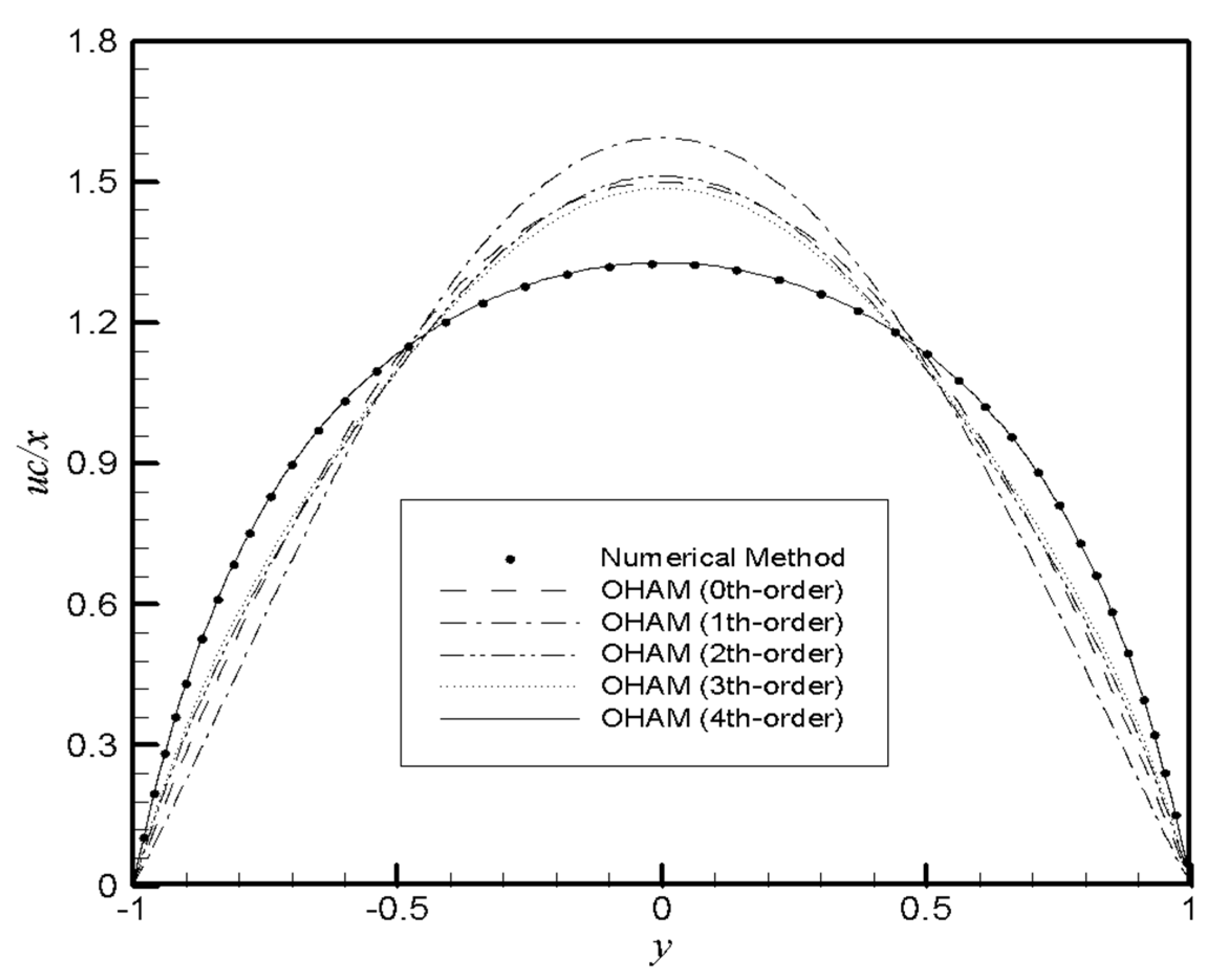
Figure 1. The analytical results for uc/x obtained by the OHAM at different orders of approximation compared with the numerical results Re = 5 and α = −1.
Mca 26 00041 g001
Figure 2. The analytical results for uc/x obtained by the DTM at different orders of approximation compared with the numerical results Re = 5 and α = −1.
Mca 26 00041 g002
Figure 3. The analytical results for uc/x obtained by the HAM at different orders of approximation compared with the numerical results Re = 5 and α = −1.
Mca 26 00041 g003
Figure 4. Comparison of CPU time of different approaches at different orders of approximation.
Mca 26 00041 g004
Figure 5. Comparison of average error of different approaches at different orders of approximation for the case of Re = 5 and α = 1.
Mca 26 00041 g005
Figure 6. Residual error of different approaches for the case of Re = 5 and α = 1.
Mca 26 00041 g006
Figure 7. Residual error of different approaches for the case of Re = 5 and α = 1.
Mca 26 00041 g007
Figure 8. Behavior of f(y) with variation of Re simulated by numerical simulation, ADM and VIM.
Mca 26 00041 g008
Figure 9. Behavior of f(y) with variation of α simulated by numerical simulation, ADM and VIM.
Mca 26 00041 g009
Figure 10. Behavior of f(y) using RKHSM with α = 1.
Mca 26 00041 g010
Figure 11. Behavior of f(y) using RKHSM with Re = 1.
Mca 26 00041 g011
Figure 12. Streamlines and velocity field for Re = 5 and α = 1.
Mca 26 00041 g012
Table 1. Comparison of the numerical solution (NS) with the OHAM and HAM by 3rd-order approximate solution and DTM (m = 10) for the case of Re = 5 and α = 1.
f(y) Error
yNSOHAMDTMHAM [29]FDM
(21 Nodes)
FDM
(41 Nodes)
|NS–OHAM||NS–DTM||NS–HAM|
0.050.079682970.079636880.081156410.079767730.07967220.07968160.000046090.001473430.00008475
0.100.158834390.158746840.161748630.159006600.1588170.1588320.000087540.002914230.00017221
0.150.236927960.236807610.241218060.237192250.2369080.2369250.000120350.004290090.00026428
0.200.313447830.313306180.319017170.313809220.3134270.3134450.000141650.005569330.00036138
0.250.387893390.387743260.394614660.388355390.3878730.387890.000150120.006721260.00046199
0.300.459783770.459637670.467500230.460346240.4597650.4597810.000146100.007716450.00056246
0.350.528661810.528530350.537188880.529319030.5286450.5286590.000131450.008527060.00065721
0.400.594097500.593988240.603224690.594836700.5940830.5940940.000109260.009127180.00073920
0.450.655690900.655607620.665184210.656491640.6556780.6556870.000083280.009493300.00080074
0.500.713074450.713017100.722679380.713908970.7130620.7130710.000057340.009604930.00083452
0.550.765914790.765880080.775360430.766749490.7659040.765910.000034700.009445640.00083470
0.600.813914110.813896530.822918840.814712140.8139030.8139090.000017580.009004720.00079803
0.650.856811000.856804210.865090880.857535780.85680.8568060.000006780.008279880.00072477
0.700.894380980.894379220.901662320.895000310.894370.8943760.000001760.007281340.00061932
0.750.926436630.926435820.932474770.926927040.9264260.9264310.000000810.006038130.00049040
0.800.952827500.952825770.957434750.953178190.9528170.9528220.000001730.004607240.00035068
0.850.973439700.973437200.976526260.973655470.973430.9734350.000002490.003086550.00021577
0.900.988195300.988193250.989828080.988297840.9881870.9881920.000002050.001632780.00010253
0.950.997051570.997050820.997537240.997078300.9970470.9970490.000000740.000485670.00002672
Table 2. Comparison of the numerical solution (NS) with the OHAM and HAM by 4th-order approximate solution and DTM (m = 20) for the case of Re = 5 and α = 1.
f(y) Error
yNSOHAMDTMHAM [29]FDM
(21 Nodes)
FDM
(41 Nodes)
|NS–OHAM||NS–DTM||NS–HAM|
0.050.079682970.079678580.079521100.079661840.07967220.07968160.000004390.000161860.00002112
0.100.158834390.158826350.158513880.158792370.1588170.1588320.000008040.000320510.00004201
0.150.236927960.236917590.236455230.236865480.2369080.2369250.000010370.000472730.00006248
0.200.313447830.313436740.312832430.313365350.3134270.3134450.000011090.000615400.00008248
0.250.387893390.387883140.387147900.387791370.3878730.387890.000010250.000745490.00010202
0.300.459783770.459775550.458923640.459662630.4597650.4597810.000008220.000860080.00012114
0.350.528661810.528656230.527705390.528522100.5286450.5286590.000005570.000956420.00013971
0.400.594097500.594094530.593065580.593940190.5940830.5940940.000002970.001031920.00015731
0.450.655690900.655689930.654606680.655517820.6556780.6556870.000000970.001084210.00017307
0.500.713074450.713074550.711963300.712888780.7130620.7130710.000000100.001111140.00018567
0.550.765914790.765915020.764804000.765721470.7659040.765910.000000220.001110790.00019331
0.600.813914110.813913760.812832580.813720030.8139030.8139090.000000340.001081520.00019408
0.650.856811000.856809820.855789010.856624770.85680.8568060.000001180.001021990.00018623
0.700.894380980.894379160.893449770.894212210.894370.8943760.000001820.000931210.00016877
0.750.926436630.926434660.925627890.926294670.9264260.9264310.000001970.000808740.00014196
0.800.952827500.952825900.952172190.952719670.9528170.9528220.000001600.000655310.00010783
0.850.973439700.973438760.972965230.973369340.973430.9734350.000000940.000474460.00007035
0.900.988195300.988194950.987918150.988159950.9881870.9881920.000000340.000277150.00003534
0.950.997051570.997051520.996958200.997041870.9970470.9970490.000000040.000093360.00000969
Table 3. Comparison of the numerical solution (NS) with the OHAM and HAM by 5th-order approximate solution and DTM (m = 30) for the case of Re = 5 and α = 1.
f(y) Error
yNSOHAMDTMHAM FDM
(21 Nodes)
FDM
(41 Nodes)
|NS–OHAM||NS–DTM||NS–HAM|
0.050.079682970.079682610.079690320.079673600.07967220.07968160.000000360.000007340.00000937
0.100.158834390.158833760.158848940.158815830.1588170.1588320.000000620.000014550.00001856
0.150.236927960.236927250.236949440.236900530.2369080.2369250.000000710.000021470.00002743
0.200.313447830.313447200.313475810.313411890.3134270.3134450.000000620.000027970.00003594
0.250.387893390.387892990.387927320.387849230.3878730.387890.000000400.000033920.00004416
0.300.459783770.459783640.459822970.459731620.4597650.4597810.000000130.000039190.00005215
0.350.528661810.528661910.528705470.528601850.5286450.5286590.000000090.000043660.00005995
0.400.594097500.594097720.594144710.594030050.5940830.5940940.000000210.000047200.00006744
0.450.655690900.655691100.655740630.655616640.6556780.6556870.000000190.000049730.00007426
0.500.713074450.713074520.713125590.712994680.7130620.7130710.000000070.000051140.00007976
0.550.765914790.765914710.765966140.765831670.7659040.765910.000000070.000051350.00008312
0.600.813914110.813913920.813964400.813830720.8139030.8139090.000000180.000050280.00008339
0.650.856811000.856810790.856858890.856731220.85680.8568060.000000200.000047890.00007977
0.700.894380980.894380830.894425090.894309100.894370.8943760.000000140.000044110.00007188
0.750.926436630.926436590.926475550.926376710.9264260.9264310.000000040.000038910.00005992
0.800.952827500.952827530.952859800.952782540.9528170.9528220.000000030.000032290.00004496
0.850.973439700.973439750.973463970.973410820.973430.9734350.000000050.000024260.00002888
0.900.988195300.988195330.988210340.988181070.9881870.9881920.000000020.000015040.00001423
0.950.997051570.997051570.997057130.997047750.9970470.9970490.000000010.000005560.00000381
Table 4. Comparison of the numerical solution (NS) with the ADM, VIM and FDM for the case of Re = 5 and α = 1.
f(y) Error
yNSADMVIMFDM
(21 Nodes)
FDM
(41 Nodes)
|NS–ADM||NS–VIM|
0.050.079682970.0796830030.0802812040.07967220.07968163.3 × 10−80.0005982340
0.10.158834390.158834450.1600140180.1588170.1588326 × 10−80.0011796280
0.150.236927960.2369281360.2386555150.2369080.2369251.76 × 10−70.0017275550
0.20.313447830.3134486170.3156736080.3134270.3134457.87 × 10−70.0022257780
0.250.387893390.387896740.3905522240.3878730.387893.35 × 10−60.0026588340
0.30.459783770.459795360.4627962210.4597650.4597811.159 × 10−50.0030124510
0.350.528661810.5286952890.5319359360.5286450.5286593.3479 × 10−50.0032741260
0.40.594097500.594181530.5975313180.5940830.5940948.403 × 10−50.0034338180
0.450.655690900.6558798570.6591755780.6556780.6556870.0001889570.0034846780
0.50.713074450.7134637760.7164983120.7130620.7130710.0003893260.0034238620
0.550.765914790.7666619340.7691680560.7659040.765910.0007471440.0032532660
0.60.813914110.8152660270.8168942570.8139030.8139090.0013519170.0029801470
0.650.856811000.8591392810.8594286380.85680.8568060.0023282810.0026176380
0.70.894380980.8982256070.8965659340.894370.8943760.0038446270.0021849540
0.750.926436630.9325595630.9281439970.9264260.9264310.0061229330.0017073670
0.80.952827500.9622772990.9540432280.9528170.9528220.0094497990.0012157280
0.850.973439700.9876287620.9741852970.973430.9734350.0141890620.0007455970
0.90.988195301.0089915050.9885310810.9881870.9881920.0207962050.0003357810
0.950.997051571.0268866190.9970776870.9970470.9970490.0298350490.0000261170
Table 5. Comparison of CPU time (second) given by OHAM, DTM and HAM at different orders of approximation for the case of Re = 5 and α = 1.
OHAMDTMHAM
OrderCPU-TimeOrderCPU-TimeOrderCPU-Time
3rd-order20.547m = 100.0783rd-order2.015
4th-order36.515m = 200.4064th-order3.219
5th-order131.25m = 3013.0305th-order6.438
Table 6. Comparison of the residual error (RError) with the RKHSM solutions for the case α = 1 and different values of Re and n.
RKHSMn = 10n = 20n = 30n = 40n = 50n = 60n = 70
Re = 51.21107 × 10−118.44965 × 10−126.85690 × 10−125.91752 × 10−125.28101 × 10−124.81348 × 10−124.45144 × 10⁻¹²
Re = 61.23870 × 10−108.63987 × 10−117.01099 × 10−116.05043 × 10−115.39960 × 10−114.92156 × 10−114.55138 × 10⁻¹¹
Re = 77.37340 × 10−105.14179 × 10−104.17230 × 10−103.60064 × 10−103.21332 × 10−102.92883 × 10−102.70854 × 10⁻¹⁰
Re = 83.05065 × 10−92.12697 × 10−91.72590 × 10−91.48942 × 10−91.32920 × 10−91.21152 × 10−91.12040 × 10⁻⁹
Re = 99.75283 × 10−96.79880 × 10−95.51670 × 10−94.76080 × 10−94.24867 × 10−93.87252 × 10−93.58124 × 10⁻⁹
Re = 102.57802 × 10−81.79689 × 10−81.45803 × 10−81.25824 × 10−81.12289 × 10−81.02348 × 10−89.46495 × 10⁻⁹
Publisher’s Note: MDPI stays neutral with regard to jurisdictional claims in published maps and institutional affiliations.