1. Introduction
2 µm laser sources are used in applications such as environmental sensing, biomedical therapies, remote sensing, directed energy, and 2 µm-band fiber communications [
1,
2,
3,
4,
5]. Applications such as fiber communications and spectral beam combination require multispectral output which is typically achieved using completely distinct and independent master oscillators [
6] or wavelength switchable sources [
7]. The ability to bring multiple 2 µm-band master oscillators into a single compact device will lead to smaller footprints and simpler design concepts for multiplexed signal generators in a 2 µm optical network, or as an integrated suite of spectrally distinct master oscillators for spectral beam combination.
Several developments now present an opportunity to develop such a compact multi-spectral laser device emitting in the 2 µm band. In 2015, Lancaster et al. [
8] demonstrated a free-space laser architecture using an ultrafast-inscribed depressed-cladding waveguide (WG) in a holmium-doped zirconium fluoride glass (Ho:ZBLAN), achieving over 1 W of lasing at 2 µm from a single WG. The considerable efficiency (>42%) of this Ho:ZBLAN “WG chip” laser represented an opportunity to realize multiple high power master oscillators in compact laser arrays of sub-millimeter pitch. Unfortunately, bulky free-space optics were needed to couple the large mode-area/low numerical aperture (NA) WGs to compact fiber components with very different mode-areas and NAs. In other later work, the free-space lenses were replaced by terminating the single mode fiber (SMF) with specific lengths of graded index fiber in a so-called graded index fiber tipped (GIF-tip) configuration [
9]. In that work the GIF-tip directly mode-matched small-core SMF to large-mode area erbium-doped ZBLAN WGs in a duplexed mode-locked 1.5 µm laser, demonstrating a way to fiber-couple the entirety of ZBLAN WG lasers. More recent work [
10] enhanced this approach by adding a mode-expansion coreless fiber section to further improve mode matching. In addition [
10] also generalizes the design principles for tailoring such GIF-tips for operation at other wavelengths and WG geometries.
By combining these key design features and innovations, herein we report on the development and characterization of a compact multispectral 2 µm laser array based on ultrafast-inscribed, wide-mode-area depressed cladding WGs in a Ho:ZBLAN substrate employing fiber Bragg gratings (FBGs) end mirrors for independent narrowband wavelength selection, tailored GIF-tips to mode-match between SMF and wide mode area WGs, and pumped by a single thulium fiber laser source. It is our understanding that this represents the first demonstration of a fiber-coupled, n-wavelength scalable multi-spectral 2 µm laser array employing a single element gain medium.
2. Materials and Methods
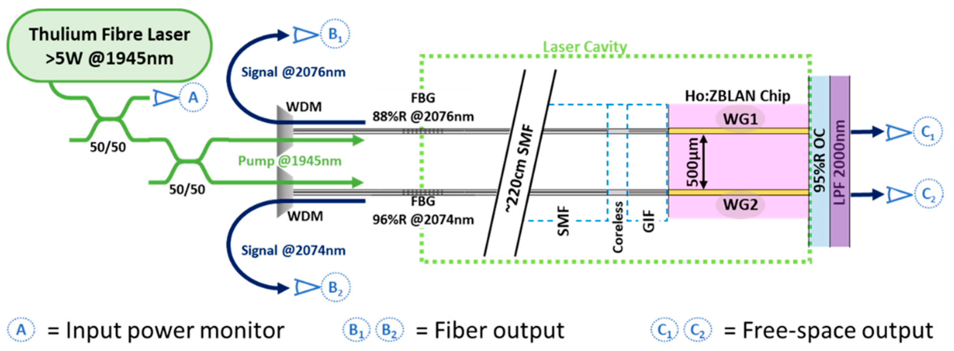
A schematic of the multichannel Ho:ZBLAN WG laser design is shown in
Figure 1. Each laser cavity is formed between a partially reflective FBG in SMF and a common R = 95% free-space resonator mirror, coupled through a holmium-doped ZBLAN WG for gain, with laser output emitted from both ends of the cavity. The free-space resonator mirror face is abutted against one ZBLAN WG facet, and at the opposite WG facet light is coupled between the WG and SMF using a section of custom-designed mode-matching fiber (e.g., GIF-tip). In-band pumping is provided by a home-built 1945 nm thulium fiber laser coupled into the cavity through the FBG. Forward-propagating signal is collected as a free-space output through the free-space resonator mirror at C
i,
Figure 1. Counter-propagating signal light is separated from the pump light path via a wavelength division multiplier (WDM) and is collected as direct fiber output at B
i,
Figure 1. The ~200 cm SMF length was chosen to be long enough to facilitate any re-splicing as might be required during setup, but would ideally be kept to a minimum for most applications. Specific physical parameters for each channel are tabulated in
Table 1.
A key component of this laser design is the mode-matching GIF-tips employed to couple light from the SMFs to the WGs. These are fusion-spliced combinations of coreless and graded-index fibers designed and fabricated as adapted from [
11]. Briefly, the fabrication process involves first splicing a length of SMF to a length of coreless fiber. The resulting spliced SMF/coreless fiber is then cleaved within the coreless fiber section at an offset from the splice point, leaving behind a length of SMF terminated by a designed length of coreless fiber. The process is then similarly repeated with GIF to add the desired length of GIF to the SMF/coreless fiber stack. The geometric parameters of the GIF-tips are noted in
Table 1. For mode-matching the key performance characteristics of a GIF-tip are divergence and beam diameter at the GIF-tip face. The GIF-tip divergences were determined by measuring the D
4σ beam diameters at 1945 nm with a pyroelectric scanning-slit camera (Ophir, NS2s-Py/9/5/STD) over ~4 mm of propagation. As the closely spaced pair of beams overlap in the far-field, a 7.9× magnifying imaging relay was fitted to the camera to image the beams near the WG aperture where the two beams are still distinct. The measured beam diameters as a function of propagation length are plotted in
Figure 2 and the divergence (half angle) is taken as the asymptotic slope of the hyperbolic fit of Gaussian beam radius as a function of propagation distance.
The WGs’ free-space emissions at ~2075 nm were similarly measured except that, due to equipment availability, a 2D pyroelectric camera (Ophir, Pyrocam VI) was used instead. These are also presented in
Figure 2. The divergence and beam waist of 1945 nm emission from SMF was similarly determined and compared using both imaging systems, confirming the equivalence of both methods within error as well as establishing a spatial resolution limit of 12 µm for these measurements.
GIF-tip and WG beam measurement and propagation fit results are presented in
Table 2. In all cases the measured beam waist diameters are 35 µm, agreeing well with the intended beam waist diameters for the GIF-tips and the expected mode field diameters for the WGs. The difference in the GIF-tip and WG divergences is primarily attributed to the ~7% difference in wavelengths used in each measurement. The position of the beam waist relative to the optical facets could not readily be determined as there was no means to calibrate the absolute position of imaging plane relative to GIF-tip/WG facet. Assuming the waist of the beam emerging from the GIF-tip is at the GIF-tip interface (per the intended design), these results suggest good mode overlap should be expected between the fundamental modes of the WG and the GIF-tip beams for efficient coupling in both directions.
To arrange the multiple GIF-tips as an array, the GIF-tip terminated fibers were rigidly pre-positioned into a glass V-groove array to affect a 500 µm pitch matching the Ho:ZBLAN WG pitch. The GIF-tips were set to protrude the V-groove by 300 µm, and bonded with UV-curable epoxy (NOA63, Norland Products Inc., Jamesburg, USA). This allowed the fibers to be aligned with their corresponding WGs as an array in a single alignment procedure. An image of the dual-channel GIF-tip array assembly is shown in
Figure 3b.
The array of WGs were fabricated by ultrafast-laser inscription into 2.5 mol% holmium-doped zirconium fluoride glass (University of Adelaide, Adelaide, Australia) as described elsewhere [
8,
12]. The waveguides have a nominal 40 µm core diameter, 110 µm cladding diameter, and 11.75 mm length, inscribed as a linear array with a 500.0 µm pitch. As the inscribed cladding is highly lossy, guided modes will largely be confined to diameters comparable or smaller than the core diameter.
The facet adjacent to the broadband 2 µm resonator mirror is polished to be perpendicular to the WG, facilitating laminated contact between the mirror and the facet. In this work the resonator mirror is R = 95% at 2075 nm and serves as a second output coupler. The small output coupling of this mirror aids in diagnostics and assembly but could be also replaced by a high reflector mirror coated directly on the WG chip. The facet adjacent to the GIF-tip is polished at an angle of 2° relative to the WG axis to mitigate potential etalons, and the GIF-tip array plane is tilted relative to the WG array plane to account for refraction into the WG chip. Because the GIF-tip face and WG facets are not parallel they cannot be brought into a laminated contact and instead were typically held at a nominal gap of ~1 µm. Both WG facets are broad-band anti-reflection (AR) coated around 2 µm (Edmond Optics) to reduce losses, whereas the GIF-tip face is uncoated in this work. The coating on the WG facets protects the optical surfaces from atmospheric moisture degradation of the fluoride glass.
The spectra of the fiber-side output (B
i, Figure 1) was collected by a wavemeter (Bristol, 771A-IR) and averaged over 64 scans of approximately 1 s duration each. Higher resolution spectra were also taken using a 1.5 GHz free-spectral range (FSR) scanning Fabry-Pérot interferometer (Thorlabs, SA200-18C) at a scan rate of 36 GHz/s to examine the underlying longitudinal modes.
To facilitate an indirect measurement of the 1945 nm pump power being supplied to the WGs during operation, the output power of each GIF-tip was measured by thermopile power sensor (Thorlabs, S401C) and calibrated against the power observed at A
Figure 1. Optical pump powers of 924 mW (channel 1) and 883 mW (channel 2) were used for the results presented herein. Laser output power was measured by thermopile power sensors (Thorlabs, S302C) at the positions B
i and C
i,
Figure 1. All power measurements are reported as an average of 100 measurements over 1 min of collection.
3. Results
Observed lasing performance for each channel is tabulated in
Table 3, with total output power presented as the sum of the outputs from both ends of the cavity (B
i and C
i,
Figure 1). It was observed that output powers at lower pump powers were unstable, likely due to the presence of a competing cavity between the uncoated GIF-tip face and the free-space output coupler, the potential etalon formed between the FBG and the GIF-tip face, as well as feedback to the pump laser from the GIF-tip face. To allow for experimental flexibility the WG substrate and the fiber array are mounted on independent multi-axis positioning stages, although it would be preferable to have rigidly bonded these two structures to a common baseplate. Because of this, there is also the potential for alignment instability (thermally or mechanically induced) between the V-groove and the WG chip which may also contribute to the observed power instability. Future work to improve this design will incorporate both anti-refection coatings on the GIF-tip face as well as a common rigid base between the fiber array and WG elements.
High and low resolution spectra of the fiber-side outputs of the laser are presented in
Figure 4. At low resolution the spectra exhibit the expected pair of distinct spectral channels (2074.3 nm and 2076.5 nm) and compare well with the measured FBG reflection peaks (2074.4 nm and 2076.6 nm). The signals are more than 25 dB above the background, and the observed linewidth is instrument resolution limited (~0.2 nm, FWHM) but in agreement with the FBG bandwidths. At higher resolution the longitudinal modes are observed, revealing that the modes are not evenly spaced over the measurement timeframe, attributed to changes in the optical path length on the timescales of the measurement and intra-cavity etalons. The average mode spacing was determined by examination of the average of the Fourier transform of nine individual scans giving an average mode spacing 46 ± 3 MHz, in agreement with the predicted FSR of 45 ± 3 MHz of the laser cavities. Occasionally the longitudinal modes would be stable through a few scans for the characterization of a single mode, giving an instrument-resolution limited FWHM of <6 MHz. Intensities were also observed to rapidly fluctuate between individual modes, again explainable by parasitic intra-cavity etalons and vibrations.
The most complicated part of the assembly process is aligning the fibers with their corresponding WGs in three angular and three spatial dimensions. This was greatly simplified by employing a commercially available glass V-groove array allowing the fiber-array assembly to be aligned to the array of WGs in one alignment procedure. Because these two components are not bonded to a common baseplate but were instead held in place by their positioning hardware, they remain more susceptible to transient misalignment due to thermal and vibrational perturbations than they might have if rigidly bonded to a common baseplate.
4. Discussion
The laser concept presented here is fundamentally a hybrid fiber/WG photonic device. Through the use of ultrafast laser inscribed WGs, parallelized lasing channels of compact pitch (500 µm) result in numerous independent lasers in a compact footprint. As each channel’s lasing wavelength is selected by an FBG, the lasing wavelengths can readily be reconfigured to match required application requirements anywhere along the gain pedestal of the Ho:ZBLAN substrate. For example, one might select wavelengths aligned with atmospheric transmission windows for propagation through air, tailor the output wavelengths to optimal gain in an array of amplifiers, or select a set of wavelengths with a specific spectral fingerprint in a molecular sensing configuration. Although in this work the FBGs were directly fusion-spliced into the cavity to limit intra-cavity losses, the design can conceivably accommodate connectorized FBGs. This would enable complete and independent reconfiguration of any or all of the device’s multiple wavelengths across the entire Ho:ZBLAN gain bandwidth without any specialist equipment or training.
Here, both free-space and fiber-coupled laser output were also simultaneously demonstrated, with the fiber-coupled output collected as a counter-propagating signal to the pump laser. This was made possible because the similarity of pump/laser wavelengths afforded by in-band pumping allow the fiber components to support and couple both wavelengths similarly. However, if the pump were instead coupled into the opposite side of the cavity using a dedicated SMF/GIF-tip, this architecture could still result in a fully fiber-coupled and reconfigurable, compact multi-spectral laser device for a number of rare-earth doped ZBLAN substrates with disparate pump/laser wavelengths.
Compared to the other reported Ho:ZBLAN depressed-cladding WG laser [
8], the absolute efficiencies measured here are low (<15% vs. ~42%). However, these results are not directly comparable due to different dopant concentrations, lengths and diameters of WGs, different intracavity losses, potential glass quality differences, and the different output coupling arrangements employed in each work. Exploration of all of these parameters were beyond the scope of this work. It does, however, suggest that improvements in this work’s design, including addressing instability-inducing power losses, should result in a better overall efficiency. Applying anti-reflective coatings to the GIF-tip facets could be an obvious first step in this direction, as well as a more rigid mounting arrangement between GIF-tip and WG substrate to limit vibration induced misalignment between these components.
In principle this design can scale to as many WGs as can be physically fit into the ZBLAN substrate, provided heat loads are adequately managed. During WG inscription, stress-induced cracking between WGs limits pitches to no smaller than ~500 µm (for the WG geometries used herein). The present substrate dimensions (~2 × 7 × 12 mm3), allowing for a ~0.75 mm margin at the edges of the WG array, can accommodate up to twelve independent channels. To date we have been able to procure substrates of up to ~40 mm in length, which in principle could support over 75 parallel lasers, (150 if WGs were written from both the top and bottom surfaces of the substrate). However, the largest V-groove array available as a standard product from our commercial supplier is 8 mm in width, so larger V-groove arrays with suitable tolerancing would need to be sourced to realize these extended configurations.
Aside from limitations of the physical geometry thermal management is frequently a scale-limiting factor. In this work up to 850 mW of power per channel is dissipated without any specific thermal management. Managing the thermal load of more lasers across the substrate width remains a challenge to be addressed in future work and, although standard active thermal management strategies might be employed, an overall increase in laser efficiency may also be a viable strategy whilst also improving output power.
5. Conclusions
The laser design presented here is a compact 2 µm oscillator capable of multiple independent spectral channels, in this case demonstrating two channels. The design can be used as either an intrinsically fiber-coupled laser through use of a reflective broadband mirror on one end of the cavity, or as a free-space laser through the use of a completely reflective FBG at the other side of the cavity. Here, both were employed simultaneously as an experimental convenience. The lasing wavelengths are also easily reconfigurable across the gain bandwidth of the Ho:ZBLAN substrate through a straightforward replacement of the FBGs, making this design highly adaptable to specific multispectral application requirements.
The observed efficiency is lower than reported in similar, indirectly comparable works, which suggests that the efficiency could exceed 45% with further design improvements. Given the clear drawbacks of an uncoated surface within the cavity (e.g., GIF-tip face) and the mechanically decoupled fiber-array/WG components, there are obvious routes to progress towards this goal. However, there are a number of other physical parameters which also may be limiting (WG geometries, dopant concentration, etc.)
In principle this laser can scale to as many WGs as can be physically fit into the ZBLAN substrate provided heat loads are adequately managed and appropriate V-groove arrays can be sourced. Currently that is limited twelve independent channels by commercially V-groove availability, but over 75 could potentially be accommodated by available ZBLAN substrates. Thermal management in larger scales of this device remains a challenge to be addressed in future work, although increasing overall laser efficiency to approach that demonstrated in other similar work would both help manage thermal load and improve output power.
Author Contributions
Conceptualization, D.Y.S. and D.G.L.; Formal analysis, D.E.O.; Funding acquisition, D.Y.S. and D.G.L.; Investigation, D.E.O., L.H. and Y.H.; Methodology, D.E.O., Y.H. and D.G.L.; Project administration, D.G.L.; Resources, D.Y.S. and D.G.L.; Supervision, D.G.L.; Visualization, D.E.O.; Writing—original draft, D.E.O.; Writing—review and editing, Y.H., D.Y.S. and D.G.L. All authors have read and agreed to the published version of the manuscript.
Funding
This research was funded by Commonwealth of Australia’s Next Generation Technologies Fund (NGTF) [Research Agreement 10738] through the NGTF Directed Energy (DE) Science and Technology (S&T) Network of Australian Universities and Industry Partners.
Data Availability Statement
The data presented in this study are available on request from the corresponding author.
Conflicts of Interest
The authors declare no conflict of interest. The funders had no role in the design of the study; in the collection, analyses, or interpretation of data; in the writing of the manuscript. The funders have provided permission for the publication of these results.
References
- Li, Z.; Heidt, A.M.; Daniel, J.M.O.; Jung, Y.; Alam, S.U.; Richardson, D.J. Thulium-doped fiber amplifier for optical communications at 2 µm. Opt. Express 2013, 21, 9289–9297. [Google Scholar] [CrossRef] [PubMed] [Green Version]
- Gunning, F.; Corbett, B. Time to Open the 2-µm Window? Opt. Photonics News 2019, 30, 42–47. [Google Scholar] [CrossRef]
- Ahmed, S.A.; Mohsin, M.; Ali, S.M.Z. Survey and technological analysis of laser and its defense applications. Def. Technol. 2021, 17, 583–592. [Google Scholar] [CrossRef]
- Sprangle, P.; Ting, A.; Penano, J.; Fischer, R.; Hafizi, B. Incoherent Combining and Atmospheric Propagation of High-Power Fiber Lasers for Directed-Energy Applications. IEEE J. Quantum. Electron. 2009, 45, 138–148. [Google Scholar] [CrossRef]
- Alharbi, A.G.; Kanwal, F.; Ghafoor, S.; Habib, N.; Kanwal, B.; Atieh, A.; Kousar, T.; Mirza, J. Performance Optimization of Holmium Doped Fiber Amplifiers for Optical Communication Applications in 2–2.15 μm Wavelength Range. Photonics 2022, 9, 245. [Google Scholar] [CrossRef]
- Kracht, D.; Sayinc, H.; Yilmaz, S.; Wysmolek, M.; Hausmann, K.; Ottenhues, C.; Wandt, D.; Wienke, A.; Neumann, J. Innovative Laser Sources Operating around 2 μm. Phys. Procedia 2016, 83, 1184–1195. [Google Scholar] [CrossRef] [Green Version]
- Qin, Q.; Yan, F.; Liu, Y.; Cui, Z.; Dan, C.; Yu, C.; Jiang, Y.; Suo, Y.; Zhou, H.; Feng, T. Twelve-Wavelength-Switchable Thulium-Doped Fiber Laser with a Multimode Fiber Bragg Grating. IEEE Photonics J. 2021, 13, 7100710. [Google Scholar] [CrossRef]
- Lancaster, D.G.; Stevens, V.J.; Michaud-Belleau, V.; Gross, S.; Fuerbach, A.; Monro, T.M. Holmium-doped 2.1 μm waveguide chip laser with an output power > 1 W. Opt. Express 2015, 23, 32664. [Google Scholar] [CrossRef] [PubMed] [Green Version]
- Lancaster, D.G.; Chen, G.Y.; Genest, J.; Hébert, N.B.; Michaud-Belleau, V. Highly coherent free-running dual-comb chip platform. Opt. Lett. 2018, 43, 1814–1817. [Google Scholar]
- Riesen, N.; Phillips, N.; Lancaster, D.G. Design guidelines for collimating or focusing graded-index fiber tips. Opt. Express 2021, 29, 29982–29995. [Google Scholar] [CrossRef] [PubMed]
- Hwang, Y.; Phillips, N.; Otten, D.E.; Riesen, N.; Lancaster, D.G. Efficient coupling between single mode fibers and glass chip waveguides via graded refractive index fiber tips. Opt. Express 2022, 30, 12294–12307. [Google Scholar] [CrossRef] [PubMed]
- Gross, S.; Lancaster, D.G.; Ebendorff-Heidepriem, H.; Monro, T.M.; Fuerbach, A.; Withford, M.J. Femtosecond laser induced structural changes in fluorozirconate glass. Opt. Mater. Express 2013, 3, 574–583. [Google Scholar] [CrossRef]
| Disclaimer/Publisher’s Note: The statements, opinions and data contained in all publications are solely those of the individual author(s) and contributor(s) and not of MDPI and/or the editor(s). MDPI and/or the editor(s) disclaim responsibility for any injury to people or property resulting from any ideas, methods, instructions or products referred to in the content. |
© 2022 by the authors. Licensee MDPI, Basel, Switzerland. This article is an open access article distributed under the terms and conditions of the Creative Commons Attribution (CC BY) license (https://creativecommons.org/licenses/by/4.0/).

 ,
, 


