Article

Performance Analysis of Multi-Hop FSOC over Gamma-Gamma Turbulence and Random Fog with Generalized Pointing Errors

1
School of Electronics and Information Engineering, Changchun University of Science and Technology, Changchun 130022, China
2
National and Local Joint Engineering Research Center of Space Optoelectronics Technology, Changchun University of Science and Technology, Changchun 130022, China
3
School of Optoelectronics, Beijing Institute of Technology, Beijing 100081, China
4
Centre for Optical and Electromagnetic Research, State Key Laboratory of Modern Optical Instrumentation, Zhejiang University, Hangzhou 310058, China
*
Author to whom correspondence should be addressed.
Photonics 2023, 10(11), 1240; https://doi.org/10.3390/photonics10111240
Submission received: 23 September 2023 / Revised: 12 October 2023 / Accepted: 24 October 2023 / Published: 8 November 2023
(This article belongs to the Special Issue Space Laser Communication and Networking Technology)

Abstract

:
The multi-hop amplify-and-forward free-space optical communication (FSOC) system is studied in random fog using the I-function, considering Gamma-Gamma atmospheric turbulence and Beckmann pointing error. Outage probability, average bit error rate and average ergodic channel capacity are obtained. Channel-state-information assisted relay performs better than fixed-gain relay under high transmitted power. Increasing the hop number significantly improves the performance. More hops are needed in medium fog than in light fog to achieve the same performance. In addition, on a single-hop link, the influence of fog channel on system performance is dominant, while atmospheric turbulence intensity, normalized jitter standard deviation and normalized boresight error have little effect on the system performance. However, on a multi-hop link, atmospheric turbulence intensity, normalized jitter standard deviation and normalized boresight error have serious effects on system performance. Compared with correcting the normalized boresight error, compensating the normalized jitter standard deviation greatly improves the multi-hop FSOC system performance. Furthermore, optimizing beam width can further improves the performance. To ensure good communication, the system should select a low-order modulation scheme.

1. Introduction

Free-space optical communication (FSOC) has the characteristics of wide bandwidth, strong resistance to radio frequency interference, and high security, which has attracted extensive attention of researchers in this field. However, because the laser beam is easily affected by factors such as atmospheric turbulence [1,2], foggy weather [3,4,5,6,7,8], and pointing errors [9,10,11] in outdoor transmission, the transmission distance of outdoor FSOC is severely limited. Many mitigation techniques have been proposed to combat the degradation of signal quality, such as adaptive optics [12,13,14], spatial diversity [15,16], and aperture averaging [17]. However, the high system complexity and high cost of these mitigation techniques make it difficult to be widely applied to outdoor FSOC systems. Therefore, in order to realize reliable long-distance transmission of outdoor FSOC, the research on multi-hop FSOC technology has received extensive attention.
In multi-hop FSOC systems, decode-and-forward (DF) relay [18,19] and amplify-and-forward (AF) relay [20,21] are two commonly used relay technologies. The DF scheme decodes and re-encodes the received signal at each relay node and then forwards it to the next node. Both its system complexity and its cost are high, and it is not suitable for multi-hop FSOC systems. However, the AF scheme only amplifies the received signal at each relay node without demodulating and recoding, so it can achieve good communication performance in a simple system.
At present, some researchers have analyzed the communication performance of AF relay systems under atmospheric turbulence [22,23,24,25,26]. For example, Datsikas et al. analyzed the outage probability (OP) and average bit error rate (ABER) for multi-hop AF relay system under Gamma-Gamma distribution atmospheric turbulence model [22]. Tang et al. further obtained the expressions of OP and ABER of multi-hop AF relay system with heterodyne detection under the combined effect of platform random jitter and Gamma-Gamma distribution atmospheric turbulence model [23]. Further, Zedini et al. studied the expression of OP, ABER, and average ergodic channel capacity for multi-hop AF relay system with intensity modulation/direct detection (IM/DD) under the combined effect of platform random jitter and Gamma-Gamma distribution atmospheric turbulence model [24]. In the simulated atmospheric turbulence device, Nor et al. experimentally verified the 10 Gbps three-hop AF relay scheme, the paper confirms that the theoretical analysis results of the Gamma-Gamma distribution atmospheric turbulence model match the experimental results [25]. Ashrafzadeh et al. gave a unified expression of OP and ABER for multi-hop AF relay system with heterodyne detection and IM/DD under the combined effect of platform random jitter and double generalized Gamma distribution atmospheric model [26]. Although some researchers have conducted theoretical studies on the performance of multi-hop AF FSOC systems in the past decade, the above research work still has shortcomings. Specifically: on the one hand, the above analysis of the multi-hop AF relay system only considers platform random jitter and does not consider the influence of the non-zero boresight error. The pointing error is cause by two factors: platform random jitter and non-zero boresight error, both of which will seriously affect the performance of the multi-hop AF relay FSOC system; on the other hand, the above research work is based on the assumption of sunny weather conditions, without considering the impact of foggy weather on the communication performance of the multi-hop AF relay FSOC system. In the actual outdoor FSOC system, the foggy weather will seriously attenuate the optical signal power and reduce the performance of the communication system. Previous studies on fog have assumed that fog is a deterministic path attenuation related to visibility. In fact, fog attenuation is a random state, and the Gamma distribution model can better describe fog attenuation [27]. Therefore, in random fog weather, this paper considers the comprehensive impact of platform random jitter and non-zero boresight error on pointing error, and establishes a multi-hop AF FSOC link model based on Gamma-Gamma distributed atmospheric turbulence.
In this work, we delve into a multi-hop AF relay FSOC system considering Gamma distribution random fog, Gamma-Gamma distribution atmospheric turbulence and Beckmann distribution generalized pointing error. By analyzing the link state, we establish a new closed expression for the probability density function (PDF) of the system signal-to-noise ratio (SNR), which is represented by the I-function [28]. Then, new closed expressions for OP, ABER, and average ergodic channel capacity of multi-hop FSOC systems are derived under fixed gain (FG) relay and channel state information (CSI) assisted relay. Finally, the simulation analyzes the influence of different parameters on the OP/ABER/average ergodic channel capacity of the system. This work contributes to the system design and performance optimization of multi-hop FSOC systems under composite channels.

2. Materials and Methods

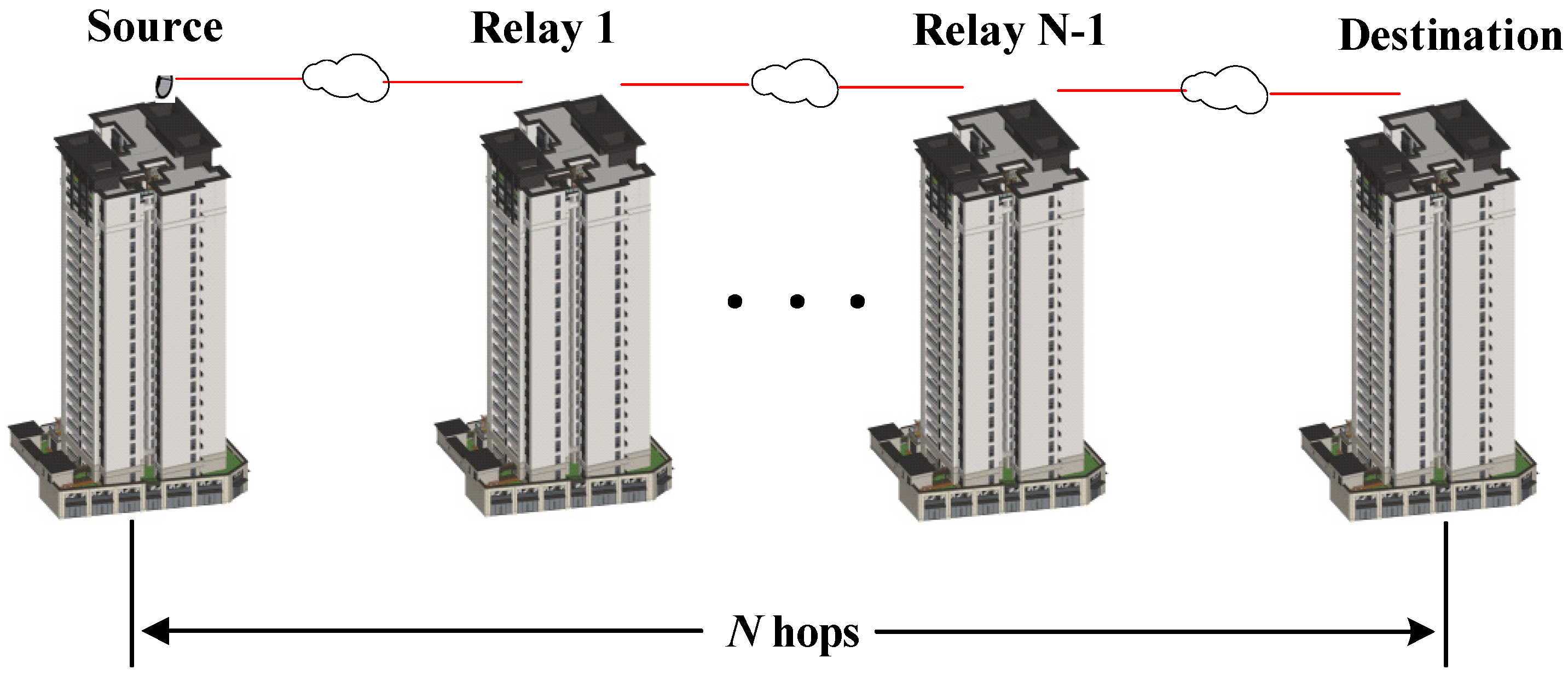
2.1. A. System Model

Figure 1 shows a schematic diagram of a multi-hop FSOC system. The modulated beam emitted by the source node is transmitted to the destination node through N 1 relay nodes. The relay nodes only amplify and forward the received signal without regeneration and shaping. We adopt two AF relay strategies: CSI-assisted relay and FG relay. It is assumed that all relay nodes can receive and transmit signals simultaneously, and there is no delay in transmission. In IM/DD system, the received electrical signal at the destination node is [29,30]:
y N = i = 1 N G i 1 h i x + i = 1 N 1 n i j = 1 N G j h j + 1 + n N
where G i ( G 0 = 1 ) represents the gain at the i-th hop, h i represents the composite channel fading of the i-th hop, x represents the transmission signal of each hop, n i N ( 0 , σ n 2 ) with power N 0 , i represents the additive white gaussian noise (AWGN) at the i-th hop. Therefore, the end-to-end SNR of the multi-hop AF relay system, γ end , is [23]:
γ end = i = 1 N 1 G i 2 i = 1 N h i 2 i N 1 N 0 , i t = i N 1 G t 2 j = i + 1 N h j 2 + N 0 , N

2.2. B. Channel Model

The composite channel model at the i-th hop link is the product of random fog, pointing error, and atmospheric turbulence which is defined as:
h i = h f , i h p , i h a , i
where h f , i , h p , i , and h a , i represent the random fog, pointing error and atmospheric turbulence of the i-th hop link, respectively. Since the time scale (milliseconds) of the above fading process is much larger than the bit interval (nanoseconds-microseconds), we assume that the composite channel is a slow fading channel. In the following, we will give the statistical models of h f , i , h p , i , and h a , i .
(1)
Random Fog Statistical Model
In the multi-hop FSOC system, fog, as an extremely severe weather condition, will seriously attenuate the optical power and thus affect the system performance. The PDF of the random fog in the i-th hop link is as follows [27]:
f h f , i ( h f , i ) = z i k i Γ k i ln 1 h f , i k i - 1 h f , i z i - 1 , 0 < h f , i < 1 ,
where Γ ( ) represents the gamma function. z i = 4.343 / β i fog d i , d i represents the length of the i-th hop link. k i > 0 and β i fog > 0 represent the shape parameter and scale parameter of the random fog, respectively. { k i = 2.32 , β i fog = 13.12 } represents light fog, { k i = 5.49 , β i fog = 12.06 } represents moderate fog, and { k i = 6 , β i fog = 23 } represents thick fog.
(2)
Atmospheric Turbulence Statistical Model
Laser beams propagating outdoors are affected by atmospheric turbulence, which causes random fluctuations in light intensity and affects the performance of multi-hop FSOC systems. Here, we adopt the Gamma-Gamma distribution atmospheric turbulence model. The PDF of atmospheric turbulence in the i-th hop link is as follows [31]:
f h a , i ( h a , i ) = 2 ( α i β i ) ( α i + β i ) / 2 Γ ( α i ) Γ ( β i ) ( h a , i ) α i + β i / 2 1 K α i β i 2 α i β i h a , i , h a , i > 0 ,
where K v represents the v-order modified Bessel function of the second kind, α i and β i represent the large-scale scattering coefficient and the small-scale scattering coefficient of the i-th hop link, respectively. The expressions of α i and β i are as follows [32]:
α i = exp 0.49 σ R , i 2 ( 1 + 1.11 σ R , i 12 / 5 ) 7 / 6 1 1 ,
β i = exp 0.51 σ R , i 2 ( 1 + 0.69 σ R , i 12 / 5 ) 5 / 6 1 1 ,
Since the transmission distance of the beam under the composite channel is short, the Rytov variance of the i-th hop link adopts the spherical wave model: σ R , i 2 = 1.23 C n 2 κ 7 / 6 d i 11 / 6 . C n 2 is the atmospheric refractive index structural constant, κ = 2 π / λ is the space wave number, and λ is the wavelength of the signal light.
(3)
Generalized Pointing Error Statistical Model
In a multi-hop FSOC system, the buildings sway randomly due to physical effects such as dynamic wind loads and thermal expansion. It causes random variations in boresight error and jitter errors at the receiver, seriously degrading system performance. We assume that the radial displacement at the receiver follows Beckmann distribution. According to Ref. [33], the modified Rayleigh distribution can accurately approximate the Beckmann distribution. Therefore, the PDF of the Beckmann distribution generalized pointing error in the i-th hop link is as follows:
f h p , i ( h p , i ) = ε mod , i 2 A mod , i ε mod , i 2 h p , i ε mod , i 2 1 , 0 h p , i A mod , i ,
where ε mod , i = ω z e q , i / 2 σ mod , i represents the ratio of the equivalent beam radius at the i-th receiving node to the modified Rayleigh distribution parameter. ω z e q , i 2 = ω d i 2 π e r f ( v i ) / ( 2 v i exp ( v i 2 ) ) , with v i = π / 2 r i / ω d i . e r f ( ) represents the error function. r i and ω d i represent the receiving aperture radius and beam width at the i-th node, respectively. The modified Rayleigh distribution parameter, σ mod , i , is as follows:
σ mod , i = 3 μ H , i 2 σ H , i 4 + 3 μ V , i 2 σ V , i 4 + σ H , i 6 + σ V , i 6 2 1 6
where μ H , i 2 and μ V , i 2 represent the boresight variance of the horizontal and vertical displacements at the i-th receiving node, respectively. σ H , i 2 and σ V , i 2 represent the jitter variance of the horizontal and vertical displacements at the i-th receiving node, respectively.
Another parameter A mod , i in Formula (8) can be expressed as:
A mod , i = A 0 , i exp 1 ε mod , i 2 1 2 ε H , i 2 1 2 ε V , i 2 1 2 ε H , i 2 σ H , i 2 1 2 ε V , i 2 σ V , i 2
where A 0 , i = e r f ( v i ) 2 represents the maximum power fraction collected at the i-th node. ε H , i = ω z e q , i / 2 σ H , i and ε V , i = ω z e q , i / 2 σ V , i represent the ratio of the equivalent beam radius to the jitter standard deviation of the horizontal or vertical direction at the i-th receiving node, respectively.
(4)
Composite Channel Statistical Model
The product of atmospheric turbulence and generalized pointing error in the i-th hop link is defined as h ap , i = h a , i h p , i , and its PDF is as follows [33]:
f h ap , i h ap , i = α i β i ε mod , i 2 A mod , i Γ α i Γ β i × G 1 , 3 3 , 0 α i β i A mod , i h ap , i ε mod , i 2 ε mod , i 2 - 1 , α i - 1 , β i - 1
where G p , q m , n is the Meijer-G function. Applying the theory of product distribution, the PDF of h i = h ap , i h f , i is as follows:
f h i h i = h i 1 h ap , i f h ap , i h ap , i f h f , i h i h ap , i d h ap , i
Putting Equations (4) and (11) into Equation (12), we obtain:
f h i ( h i ) = α i β i ε mod , i 2 z i k i h i z i 1 A mod , i Γ α i Γ β i Γ k i   h i ln h ap , i h i k i 1 h ap , i z i G 1 , 3 3 , 0 α i β i A mod , i h ap , i ε mod , i 2 ε mod , i 2 - 1 , α i - 1 , β i - 1 d h ap , i
According to the definition of the Meijer-G, the above formula is expanded as:
f h i ( h i ) = α i β i ε mod , i 2 z i k i h i z i 1 A mod , i Γ α i Γ β i Γ k i   × 1 2 π j l Γ s + ε mod , i 2 1 Γ s + α i 1 Γ s + β i 1 Γ s + ε mod , i 2 α i β i A mod , i s d s   × h i ln h ap , i h i k i 1 h ap , i z i + s d h ap , i
where j = 1 , l represents the appropriate integral contours in the s-plane. Setting t = ln h ap , i / h i and use [34] (Equation (3.381.4)). The internal integral of the above formula with respect to h a p , i can be expressed as:
I 1 = h i ln h ap , i h i k i 1 h ap , i z i + s d h ap , i = h i z i + s + 1 0 t k i 1 e t z i s 1 d t   = h i z i + 1 + s Γ k i z i s 1 k i = h i z i + 1 + s Γ k i Γ k i s + z i 1 Γ k i s + z i
Putting Equation (15) into Equation (14). After simplification, we can obtain:
f h i ( h i ) = α i β i ε mod , i 2 z i k i A mod , i Γ α i Γ β i   1 2 π j l Γ s + ε mod , i 2 1 Γ s + α i 1 Γ s + β i 1 Γ k i s + z i 1 Γ s + ε mod , i 2 Γ k i s + z i α i β i A mod , i h i s d s
The above formula can be simplified by I-function [28]. Therefore, the PDF of the composite channel containing random fog, Gamma-Gamma distribution atmospheric turbulence and Beckmann distribution generalized pointing error, f h i ( h i ) , is as follows:
f h i ( h i ) = α i β i ε mod , i 2 z i k i A mod , i Γ α i Γ β i I 2 , 4 4 , 0 α i β i A mod , i h i ε mod , i 2 , 1 , 1 , z i , 1 , k i ε mod , i 2 - 1 , 1 , 1 , α i - 1 , 1 , 1 , β i - 1 , 1 , 1 , z i 1 , 1 , k i
where I p , q m , n is the I-function.

3. Statistical Model of SNR

3.1. A. Statistical Model of SNR for Single Hop Links

We adopt the IM/DD detection method with OOK modulation and assume that the transmitted signal x has an average power constraint E x = 1 . Then, the SNR of the received signal for a single-hop link can be expressed as [35]:
γ i = P t 2 E 2 x σ n 2 h i 2 = γ i ¯ h i 2
where P t represents the emitted optical power. According to the principle of variable transformation, we obtain the PDF of γ i :
f γ i γ i = 1 2 γ i γ i ¯ f h i γ i γ i ¯
Putting Equation (17) into Equation (19), f γ i γ i is as follows:
f γ i ( γ i ) = α i β i ε mod , i 2 z i k i 2 A mod , i Γ α i Γ β i γ i γ i ¯ I 2 , 4 4 , 0 α i β i A mod , i γ i γ i ¯ ε mod , i 2 , 1 , 1 , z i , 1 , k i ε mod , i 2 - 1 , 1 , 1 , α i - 1 , 1 , 1 , β i - 1 , 1 , 1 , z i 1 , 1 , k i
Integrating (20) as F γ i ( γ i ) = 0 γ f γ i ( γ i ) d γ i , we obtain:
F γ i ( γ i ) = 0 γ α i β i ε mod , i 2 z i k i 2 A mod , i Γ α i Γ β i γ i γ i ¯ I 2 , 4 4 , 0 α i β i A mod , i γ i γ i ¯ ε mod , i 2 , 1 , 1 , z i , 1 , k i ε mod , i 2 - 1 , 1 , 1 , α i - 1 , 1 , 1 , β i - 1 , 1 , 1 , z i 1 , 1 , k i d γ i   = α i β i ε mod , i 2 z i k i 2 A mod , i Γ α i Γ β i γ i ¯ × 0 γ γ i 1 2 + s 2 d γ i   × 1 2 π j l Γ s + ε mod , i 2 1 Γ s + α i 1 Γ s + β i 1 Γ k i s + z i 1 Γ s + ε mod , i 2 Γ k i s + z i α i β i A mod , i γ i ¯ s d s
where the internal integral about γ i can be simplified as:
0 γ γ i 1 2 + s 2 d γ i = γ i 1 2 + s 2 Γ s 2 + 1 2 Γ s 2 + 3 2
Putting Equation (22) into Equation (21). After simplification, we can obtain:
F γ i ( γ i ) = α i β i ε mod , i 2 z i k i 2 A mod , i Γ α i Γ β i γ i γ i ¯   × 1 2 π j l Γ s + ε mod , i 2 1 Γ s + α i 1 Γ s + β i 1 Γ k i s + z i 1 Γ s 2 + 1 2 Γ s + ε mod , i 2 Γ k i s + z i Γ s 2 + 3 2 α i β i A mod , i γ i γ i ¯ s d s
The above formula can be expressed by I-function, and according to [36] (Equation 7.2), we can obtain:
F γ i ( γ i ) = ε mod , i 2 z i k i 2 Γ α i Γ β i I 3 , 5 4 , 1 α i β i A mod , i γ i γ i ¯ 1 , 1 2 , 1 , ε mod , i 2 + 1 , 1 , 1 , z i + 1 , 1 , k i ε mod , i 2 , 1 , 1 , α i , 1 , 1 , β i , 1 , 1 , z i , 1 , k i , 0 , 1 2 , 1

3.2. B. Statistical Model of SNR for Multi-Hop Links

There are two common relay modes for multi-hop AF relay systems: CSI-assisted relay and FG relay. The CSI-assisted relay amplifies the received signal of the i-th hop link with the inverse of the channel. Its gain is G i = 1 / h i . Compared with CSI-assisted relay, FG relay is easier to deploy but it sacrifices system performance. The FG relay amplifies the received signal of the i-th hop link with a fixed multiple, and its gain is G i = C i 1 N 0 , i 1 , where C i is a positive constant ( C 0 = 1 ). The end-to-end SNR of N-hop CSI-assisted relay, γ end , CA , and N-hop FG relay, γ end , FG , are as follows [23,24]:
γ end , CA = i = 1 N 1 γ i 1
γ end , FG = i = 1 N m = 1 i C m 1 γ m 1
According to the above formulas, it is difficult to obtain the exact PDF expressions for γ end , CA and γ end , FG . Therefore, in order to facilitate the calculation, the upper bound for γ end , CA and γ end , FG can be expressed uniformly as [23,24]:
γ ub = 1 N i = 1 N ψ i γ i l i N
where ψ i = C i N i N , l i = N + 1 i represent FG relay. ψ i = 1 , l i = 1 represent the CSI-assisted relay. We adopt the method proposed in Ref. [37], the PDF of γ ub is as follows:
f γ ub γ = 1 γ 1 2 π j l γ s E γ ub s d s = 1 γ 1 2 π j l γ s 1 N s i = 1 N ψ i s E γ i l i s N d s
where E γ i l i s N represents the l i s N -order moment of γ i , which is defined as:
E γ i l i s N = 0 γ i l i s N f γ i γ i d γ i
Putting Equation (18) into the above formula, we can obtain:
E γ i l i s N = α i β i ε mod , i 2 z i k i 2 A mod , i Γ α i Γ β i γ i ¯   × 0 γ i l i s N 1 2 I 2 , 4 4 , 0 α i β i A mod , i γ i γ i ¯ ε mod , i 2 , 1 , 1 , z i , 1 , k i ε mod , i 2 - 1 , 1 , 1 , α i - 1 , 1 , 1 , β i - 1 , 1 , 1 , z i 1 , 1 , k i d γ i
Setting γ i = t , and using the identity [38] (2.25.2.1) in (30), after simplification, we can obtain:
E γ i l i s N = α i β i ε mod , i 2 z i k i A mod , i Γ α i Γ β i γ i ¯   × Γ ε mod , i 2 + 2 l i N s Γ α i + 2 l i N s Γ β i + 2 l i N s Γ k i z i + 2 l i N s Γ ε mod , i 2 + 1 + 2 l i N s Γ k i z i + 1 + 2 l i N s α i β i A mod , i γ i ¯ 2 l i N s + 1
Substituting the above equation into Equation (28). After simplification, we can obtain:
f γ ub γ = i = 1 N ε mod , i 2 z i k i Γ α i Γ β i γ   × 1 2 π j l i = 1 N Γ ε mod , i 2 + 2 l i N s Γ α i + 2 l i N s Γ β i + 2 l i N s Γ k i z i + 2 l i N s i = 1 N Γ ε mod , i 2 + 1 + 2 l i N s Γ k i z i + 1 + 2 l i N s   N γ i = 1 N ψ i α i β i A mod , i γ i ¯ 2 l i N s d s
The above formula can be simplified by I-function:
f γ ub γ = i = 1 N ε mod , i 2 z i k i Γ α i Γ β i γ I 2 N , 4 N 4 N , 0 N γ i = 1 N ψ i α i β i A mod , i γ i ¯ 2 l i N J 1 J 2
where
J 1 = ε mod , 1 2 + 1 , 2 l 1 N , 1 , z 1 + 1 , 2 l 1 N , k 1 , ... , ε mod , N 2 + 1 , 2 l N N , 1 , z N + 1 , 2 l N N , k N ,
J 2 = ε mod , 1 2 , 2 l 1 N , 1 , α 1 , 2 l 1 N , 1 , β 1 , 2 l 1 N , 1 , z 1 , 2 l 1 N , k 1 , ... , ε mod , N 2 , 2 l N N , 1 , α N , 2 l N N , 1 , β N , 2 l N N , 1 , z N , 2 l N N , k N .
Integrating (33) as F γ ub ( γ ) = 0 γ γ ub γ d γ , we obtain:
F γ ub ( γ ) = 0 γ i = 1 N ε mod , i 2 z i k i Γ α i Γ β i γ I 2 N , 4 N 4 N , 0 N γ i = 1 N ψ i α i β i A mod , i γ i ¯ 2 l i N J 1 J 2 d γ i   = i = 1 N ε mod , i 2 z i k i Γ α i Γ β i 0 γ γ s 1 d γ   × 1 2 π j l i = 1 N Γ ε mod , i 2 + 2 l i N s Γ α i + 2 l i N s Γ β i + 2 l i N s Γ k i z i + 2 l i N s i = 1 N Γ ε mod , i 2 + 1 + 2 l i N s Γ k i z i + 1 + 2 l i N s N i = 1 N ψ i α i β i A mod , i γ i ¯ 2 l i N s d s
where the internal integral with respect to γ is:
0 γ γ s 1 d γ = γ s Γ s Γ s + 1
Substituting the above equation into Equation (34). After simplification, we obtain:
F γ ub ( γ ) = i = 1 N ε mod , i 2 z i k i Γ α i Γ β i   × 1 2 π j l i = 1 N Γ ε mod , i 2 + 2 l i N s Γ α i + 2 l i N s Γ β i + 2 l i N s Γ k i z i + 2 l i N s Γ s i = 1 N Γ ε mod , i 2 + 1 + 2 l i N s Γ k i z i + 1 + 2 l i N s Γ 1 s   N γ i = 1 N ψ i α i β i A mod , i γ i ¯ 2 l i N s d s
The above formula can be simplified by I-function. After simplification, we obtain:
F γ ub ( γ ) = i = 1 N ε mod , i 2 z i k i Γ α i Γ β i I 2 N + 1 , 4 N + 1 4 N , 1 N γ i = 1 N ψ i α i β i A mod , i γ i ¯ 2 l i N 1 , 1 , 1 , J 1 J 2 , 0 , 1 , 1

4. Performance Analysis

4.1. A. Outage Probability

In the FSOC system, OP is a key indicator to judge the reliability of the communication link. It is defined as the probability that the system SNR falls below the threshold SNR ( P out = Pr γ ub γ th ). Equation (24) is the closed expression for the OP of single-hop link. Equation (37) is the closed expression for the OP of CSI-assisted relay and FG relay.

4.2. B. Average Bit Error Rate

ABER is a key indicator to evaluate the communication quality of FSOC system. The ABER of various binary and nonbinary modulations can be uniformly expressed as [29,39]:
P b = δ 2 Γ p l = 1 n q l p 0 γ p 1 e q l γ F γ ub γ d γ
where the values of δ , p , q l , and n represent different modulation schemes. Table 1 shows the specific parameters under the two modulation types of OOK and PAM. In IM/DD FSOC links, OOK and PAM are two typical modulation methods, and both methods have been effectively used in field experiments [40,41,42]. Both OOK and PAM modulation types have their own advantages and disadvantages: OOK has the advantage of strong resistance to atmospheric turbulence, but the disadvantage is low spectral efficiency; M-PAM has the advantage of high spectral efficiency, and the theoretical maximum spectral efficiency of M-PAM is log 2 M times higher than that of OOK. However, the disadvantage of M-PAM is its weak antiturbulence ability. In summary, it is very meaningful to carry out ABER performance research under two modulation methods: OOK and PAM.
Substitute Equation (36) into Equation (38). We obtain the expression of ABER for N-hop links:
P b = δ 2 Γ p i = 1 N ε mod , i 2 z i k i Γ α i Γ β i l = 1 n q l p 0 γ p s 1 e q l γ d γ   × 1 2 π j l i = 1 N Γ ε mod , i 2 + 2 l i N s Γ α i + 2 l i N s Γ β i + 2 l i N s Γ k i z i + 2 l i N s Γ s i = 1 N Γ ε mod , i 2 + 1 + 2 l i N s Γ k i z i + 1 + 2 l i N s Γ 1 s   N i = 1 N ψ i α i β i A mod , i γ i ¯ 2 l i N s d s
where the internal integral with respect to γ is:
0 γ p s 1 e q l γ d γ = q l p + s Γ s + p
Substituting the above equation into Equation (39). After simplification, we obtain:
P b = δ 2 Γ p i = 1 N ε mod , i 2 z i k i Γ α i Γ β i   × l = 1 n 1 2 π j l i = 1 N Γ ε mod , i 2 + 2 l i N s Γ α i + 2 l i N s Γ β i + 2 l i N s Γ k i z i + 2 l i N s Γ s Γ s + p i = 1 N Γ ε mod , i 2 + 1 + 2 l i N s Γ k i z i + 1 + 2 l i N s Γ 1 s   N q l i = 1 N ψ i α i β i A mod , i γ i ¯ 2 l i N s d s
The above formula is simplified by I-function, and then the ABER of the N-hop link is:
P b = δ 2 Γ p i = 1 N ε mod , i 2 z i k i Γ α i Γ β i l = 1 n I 2 N + 2 , 4 N + 1 4 N , 2 N q l i = 1 N ψ i α i β i A mod , i γ i ¯ 2 l i N 1 , 1 , 1 , 1 p , 1 , 1 , J 1 J 2 , 0 , 1 , 1
Similarly, taking Equation (21) into Equation (36) and performing a series of simplifications, we obtain the ABER of a single-hop link. Here, we directly give the expression for the ABER of a single-hop link, and do not repeat it in the text:
P b = δ ε mod , i 2 z i k i 4 Γ p Γ α i Γ β i l = 1 n I 4 , 5 4 , 2 α i β i A mod , i γ i ¯ q l 1 , 1 2 , 1 , 1 p , 1 2 , 1 , ε mod , i 2 + 1 , 1 , 1 , z i + 1 , 1 , k i ε mod , i 2 , 1 , 1 , α i , 1 , 1 , β i , 1 , 1 , z i , 1 , k i , 0 , 1 2 , 1

4.3. C. Average Ergodic Channel Capacity

The average ergodic channel capacity is used to describe the maximum amount of information that the channel can transmit, which is defined as the highest transmission rate when the bit error rate tends to zero. The average ergodic channel capacity of an IM/DD system, C erg , is expressed as [35]:
C erg = 1 ln 2 0 ln 1 + θ γ f γ γ d γ
where θ = e / 2 π . Taking Equation (32) into Equation (44) with ln 1 + θ γ = G 2 , 2 1 , 2 θ γ 1 , 1 1 , 0 . We can obtain the average ergodic channel capacity of N-hop links:
C erg = 1 ln 2 i = 1 N ε mod , i 2 z i k i Γ α i Γ β i 0 γ s 1 G 2 , 2 1 , 2 θ γ 1 , 1 1 , 0 d γ   × 1 2 π j l i = 1 N Γ ε mod , i 2 + 2 l i N s Γ α i + 2 l i N s Γ β i + 2 l i N s Γ k i z i + 2 l i N s i = 1 N Γ ε mod , i 2 + 1 + 2 l i N s Γ k i z i + 1 + 2 l i N s   N i = 1 N ψ i α i β i A mod , i γ i ¯ 2 l i N s d s
We use the identity [38] (Equation (2.24.2.1)). Then the internal integral with respect to γ is expressed as:
0 γ s 1 G 2 , 2 1 , 2 θ γ 1 , 1 1 , 0 d γ = Γ s + 1 Γ 2 s Γ s + 1 θ s
Substituting the above equation into Equation (45). After simplification, we obtain:
C erg = 1 ln 2 i = 1 N ε mod , i 2 z i k i Γ α i Γ β i   × 1 2 π j l i = 1 N Γ ε mod , i 2 + 2 l i N s Γ α i + 2 l i N s Γ β i + 2 l i N s Γ k i z i + 2 l i N s Γ 2 s Γ 1 s i = 1 N Γ ε mod , i 2 + 1 + 2 l i N s Γ k i z i + 1 + 2 l i N s Γ s + 1   N θ i = 1 N ψ i α i β i A m o d , i γ i ¯ 2 l i N s d s
The above formula is simplified by I-function, then average ergodic channel capacity of N-hop link is as follows:
C erg = 1 ln 2 i = 1 N ε mod , i 2 z i k i Γ α i Γ β i I 2 N + 2 , 4 N + 1 4 N + 1 , 1 N θ i = 1 N ψ i α i β i A mod , i γ i ¯ 2 l i N 0 , 1 , 1 , J 1 , 1 , 1 , 1 J 2 , 0 , 1 , 2
Similarly, taking Equation (21) into Equation (37) and performing a series of simplifications, we obtain the C erg of a single-hop link. Here we directly give the C erg of a single-hop link, and do not repeat the description in the text:
C erg = ε mod , i 2 z i k i 2 ln 2 Γ α i Γ β i I 4 , 5 5 , 1 α i β i A m o d , i γ i ¯ θ 0 , 1 2 , 1 , ε mod , i 2 + 1 , 1 , 1 , z i + 1 , 1 , k i , 1 , 1 2 , 1 ε mod , i 2 , 1 , 1 , α i , 1 , 1 , β i , 1 , 1 , z i , 1 , k i , 0 , 1 2 , 2

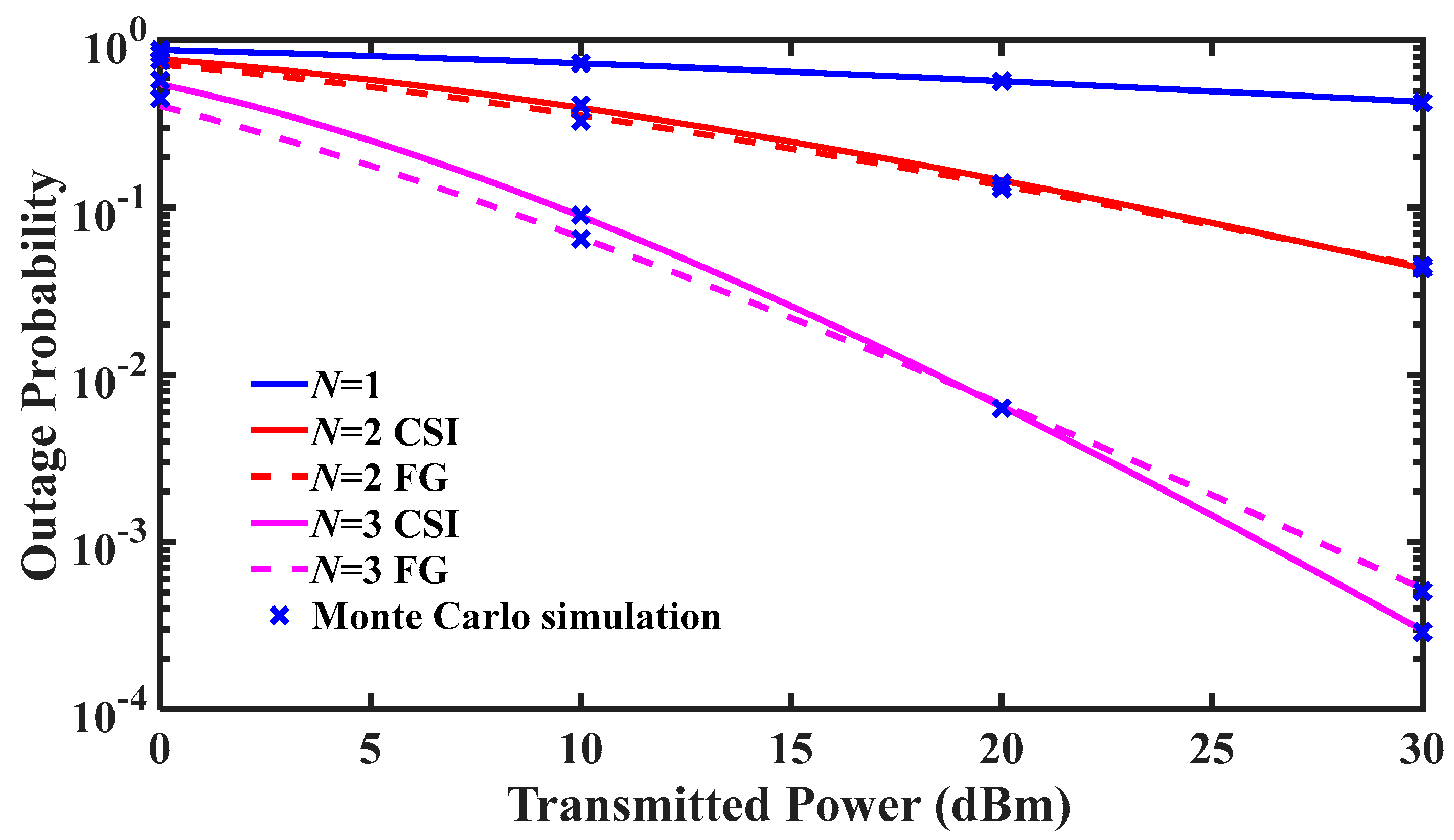
5. Numerical Results and Analysis

In this section, we simulate and analyze the communication performance of the N-hop AF relay FSOC system under the composite channel. To simplify the simulation and without loss of generality, we assume that the link lengths between any two adjacent nodes in the N-hop AF relay FSOC system are equal ( d i = d / N ). In addition, it is assumed that each node has the same communication transceiver. That is, each hop of the CSI-assisted relay and the FG relay has the same average SNR. Additionally, we use Monte Carlo simulations to verify the accuracy of the above closed expressions. Unless otherwise specified, typical values of system parameters and channel parameters are shown in Table 2:
Figure 2 demonstrates the effects of CSI-assisted relay and FG relay on the N-hop FSOC system OP under light fog. The system OP decreases as the transmitted power increases. In addition, for CSI-assisted relay and FG relay systems, when the transmitted power is fixed, increasing the number of hops can significantly reduce the system OP. For example, when N = 1 , the OPs of P t = 10   dBm and P t = 30   dBm are 0.73 and 0.43 , respectively. For the CSI-assisted relay system, when P t = 30   dBm , the OPs of N = 2 and N = 3 are 4.32 × 10 2 and 2.95 × 10 4 , respectively. The reason is that increasing the transmitted power means increasing the SNR of each hop link, which reduces the system OP. Since the total link length is fixed, increasing the number of hops shortens the distance between two adjacent nodes, which greatly reduces the probability that the channel of each hop link is in deep fading. Therefore, the SNR of each hop link is significantly increased, and the OP of the system is significantly reduced. According to Figure 2, when the number of hops is fixed, under low transmitted power, the OP of the FG relay system is lower than that of the CSI-assisted relay system. However, under high transmitted power, the OP of the CSI-assisted relay system is lower than that of the FG relay system. For example, when N = 3 and P t = 10   dBm , the OPs of the CSI-assisted relay system and the FG relay system are 0.1086 and 8.9 × 10 2 , respectively. When N = 3 and P t = 30   dBm , the OPs of the CSI-assisted relay system and the FG relay system are 2.95 × 10 4 and 5.27 × 10 4 , respectively. The reason is that CSI-assisted relay assumes that the first transmitter sends a reference signal with known characteristics, and the receiver at the next relay point can determine the distortion caused by composite channel fading. In principle, it is possible to correct such distortion, but the CSI-assisted relay is rarely perfect because the received signal is polluted by noise. This implies that CSI-assisted relay works best when the transmitted power is very high (high SNR), the algorithms used to determine the CSI of link may “ignore” noise. However, they give incorrect results when the transmitted power is very low (low SNR). Consequently, FG relay links can outperform CSI-assisted relay links when the transmitted power is low. According to Figure 2, the overall trend of the OP curves of the CSI-assisted relay and the FG relay is consistent. Therefore, in the following analysis, in order to avoid repeated descriptions, we only describe the case of CSI-assisted relay in detail.
Figure 3 demonstrates the effects of light fog (LF) and medium fog (MF) on the OP of N-hop FSOC system, which considers CSI-assisted relays. The system OP of the MF channel is higher than that of the LF channel. For example, when N = 3 and P t = 30   dBm , the system OPs of LF channel and MF channel are 2.95 × 10 4 and 1.06 × 10 1 , respectively. The reason is that the optical power attenuation of the MF channel is greater than that of the LF channel. Therefore, in the case of fixed system noise, the SNR of the MF channel is lower than that of the LF channel and the OP of the MF channel is higher than that of the LF channel. This also means that the MF channel needs more hops to achieve the same communication performance as the LF channel.
Figure 4 demonstrates the effects of different atmospheric refractive index structure constants ( C n 2 ) on the OP of N-hop FSOC system, which considers CSI-assisted relays and light fog weather. Table 3 shows the intensity of atmospheric turbulence corresponding to different C n 2 . When N = 2 , the Rytov variances of each hop link corresponding to C n 2 = 2 × 10 14 , C n 2 = 6 × 10 14 , C n 2 = 2 × 10 13 , and C n 2 = 6 × 10 13 are σ R 2 = 0.2350 , σ R 2 = 0.7049 , σ R 2 = 2.3498 , and σ R 2 = 7.0495 , respectively. Since σ R 2 0.3 , 0.3 σ R 2 < 5 and σ R 2 5 represent weak, moderate and strong turbulence, respectively [43,44], C n 2 = 2 × 10 14 , C n 2 = 6 × 10 14 , C n 2 = 2 × 10 13 , and C n 2 = 6 × 10 13 represent weak, moderate, moderate, and strong turbulence, respectively. In Figure 4, in the case of fixed transmitted power, when C n 2 is increased, the OP of the single-hop FSOC system is almost unchanged, while with the increase in C n 2 , the OP of the multi-hop FSOC system increases. For example, when P t = 30   dBm and N = 1 , the OPs with C n 2 = 6 × 10 14 (Moderate) and C n 2 = 6 × 10 13 (Strong) are 4.28 × 10 1 and 4.37 × 10 1 , respectively, and the system OP is almost unchanged. When P t = 30   dBm and N = 3 , the OPs with C n 2 = 6 × 10 14 (Moderate) and C n 2 = 6 × 10 13 (Moderate) are 2.95 × 10 4 and 7.20 × 10 4 , respectively, and the system OP increases by about two times. The reason is that when the total link length is fixed, on a single-hop link, the optical power attenuation caused by fog is more serious than that caused by atmospheric turbulence. Therefore, increasing the atmospheric turbulence intensity has little effect on the system SNR, and the system OP is basically unchanged. Increasing the number of hops shortens the length of each hop link, which leads to a significant reduction in the optical power attenuation caused by fog at each hop link. As a result, the optical power attenuation caused by atmospheric turbulence at each hop link cannot be ignored. Increasing the atmospheric turbulence intensity leads to an increase in the optical power attenuation of each hop link, which reduces the SNR of each hop link and increases the OP of the N-hop FSOC system. In short, on a single-hop link, the atmospheric turbulence intensity has little effect on the system performance. When the number of hops is increased, the influence of atmospheric turbulence intensity on the multi-hop FSOC cannot be ignored. Increasing the atmospheric turbulence intensity reduces multi-hop FSOC system performance.
Figure 5a demonstrates the effects of different normalized jitter standard deviations on the OP of N-hop FSOC system, which considers CSI-assisted relays and light fog weather. With a fixed transmitted power, the OP of a single-hop FSOC system changes little by increasing the normalized jitter standard deviation. The OP of a multi-hop FSOC system increases significantly with increasing the normalized jitter standard deviation. For example, when N = 1 and P t = 30   dBm , the OPs with σ H / r = σ V / r = 3 and σ H / r = σ V / r = 7 are 4.28 × 10 1 and 5.26 × 10 1 , respectively, and the system OP is basically unchanged. When N = 3 and P t = 30   dBm , the OPs with σ H / r = σ V / r = 3 and σ H / r = σ V / r = 7 are 2.95 × 10 4 and 1.25 × 10 2 , respectively, and the system OP increases by about two orders. The reason is that when the total link length is fixed, on a single-hop link, the optical power attenuation caused by fog is more serious than that caused by normalized jitter standard deviation. Therefore, increasing the normalized jitter standard deviation has little effect on the system SNR, and the system OP is basically unchanged. As the number of hops increases, the optical power attenuation caused by fog at each hop link decreases significantly. Increasing the normalized jitter standard deviation significantly reduces the SNR of each hop link, thereby significantly reduces the SNR of the N-hop FSOC system, and significantly increases the OP of the N-hop FSOC system. Figure 5b demonstrates the effects of different normalized boresight errors on the OP of N-hop FSOC system, which considers CSI-assisted relays and light fog weather. With a fixed transmitted power, the OP of a single-hop FSOC system changes little by increasing the normalized boresight error. With the increase in normalized boresight error, the OP of the multi-hop FSOC system increases significantly. For example, when N = 1 and P t = 30   dBm , the OPs with μ H / r = μ V / r = 3 and μ H / r = μ V / r = 7 are 4.28 × 10 1 and 5.25 × 10 1 , respectively, and the system OP is basically unchanged. When N = 3 and P t = 30   dBm , the OPs with μ H / r = μ V / r = 3 and μ H / r = μ V / r = 7 are 2.95 × 10 4 and 3.1 × 10 3 , respectively, and the system OP increases by about one order. The reason for this phenomenon is similar to Figure 5a, and we do not repeat the description here. In the multi-hop FSOC system, from the comparison of Figure 5a,b, the variation in the system OP caused by increasing the normalized jitter standard deviation is greater than that caused by increasing the normalized boresight error. Therefore, in the multi-hop FSOC system, compared with correcting the boresight error of each hop link, compensating for the platform jitter error of each hop link can significantly improve the system communication performance.
Figure 6a demonstrates the OP versus normalized beamwidth for the N-hop FSOC system under LF and MF weather conditions, which considers CSI-assisted relays. The total link length is 1.2 km, and the transmitted optical power is 10 dBm. According to Figure 6a, the normalized beam width has an optimum value that minimizes the OP of an N-hop FSOC system. On one hand, in the case that the normalized beam width is lower than the critical value, an excessively narrow beam width leads to misalignment, which increases the OP of the N-hop FSOC system. On the other hand, above the critical value, the excessive beam width will reduce the optical power received by the optical antenna at each hop link, which reduces the SNR and increases the system OP. In Figure 6a, as the number of hops increases, the optimal beam width shows an increasing trend, and the optimal normalized beam width of LF is wider than that of MF. For example, under the LF condition, the optimal normalized beam widths for each hop link corresponding to N = 3 and N = 5 are 9.7 and 10.9, respectively. When N = 5 , the optimal normalized beam widths for each hop link corresponding to LF and MF are 10.9 and 9.7, respectively. In the previous analysis, we have illustrated that as the number of hops increases, the impact of the pointing error on the system OP becomes severe. To minimize the system OP, a wider normalized beam width needs to be used to suppress pointing errors. Similarly, the received optical power per hop at the LF channel is higher than that at the MF channel. Therefore, compared with the MF channel, the pointing error at the LF channel has a more severe impact on the system OP. To minimize the system OP, a wider normalized beam width needs to be used in the LF channel to suppress pointing errors. Figure 6b demonstrates the OP versus normalized beamwidth for the N-hop FSOC system under different total link length, which considers CSI-assisted relays. As shown in Figure 6b, reducing the total link length widens the optimal normalized beam width. For example, when N = 3 , the optimal normalized beam widths for each hop link corresponding to d = 0.6   km and d = 1.8   km are 11.6 and 8.9, respectively. The reason is similar to that mentioned above, and we do not repeat here. To sum up, increasing the number of hops or decreasing the total link length results in an increase in the optimal normalized beam width at per hop link. The optimal normalized beam width in LF is wider than that in MF. In an actual multi-hop FSOC system, it is very important to select an appropriate normalized beam width for different link states.
Figure 7a demonstrates the effects of different total link length on the OP of N-hop FSOC system, which considers CSI-assisted relays and light fog weather. Increasing the total link length increases the system OP. For example, when N = 3 , P t = 20   dBm , the system OPs corresponding to d = 1   km and d = 2   km are 3.14 × 10 5 and 6.36 × 10 2 , respectively. The reason is that increasing the total link length reduces the optical power received at the receiving end, which reduces the system SNR and increases the system OP. In addition, even if the total link length is 1 km, the OP of the single-hop link is still high, and multi-hop link can significantly reduce the OP. The reason is that foggy weather greatly attenuates the optical power of the link, which causes the single-hop link to be unable to communicate at a length of 1 km. Therefore, more relay nodes need to be set up between the source node and the target node to ensure communication quality. Figure 7b demonstrates the effects of different SNR threshold on the N-hop FSOC OP, which considers CSI-assisted relays and light fog weather. As the SNR threshold increases, the system OP in both the LF and MF channels decreases. For example, in the LF channel, when N = 3 and P t = 20   dBm , the system OPs corresponding to γ th = 2 dB and γ th = 10 dB are 3.6 × 10 3 and 1.14 × 10 2 , respectively. The reason is that as the SNR threshold increases, Pr γ ub γ th will increase, so the OP will increase. To sum up, by reducing the total link length and SNR threshold, the stability of multi-hop FSOC systems can be improved.
Figure 8 demonstrates the effects of different modulation orders on the ABER of N-hop FSOC system, which considers CSI-assisted relays and light fog weather. The system ABER increases as the modulation order increases. The reason is that as the modulation order increases, the voltage interval of the M-PAM signal becomes smaller and more susceptible to link noise. Therefore, as the modulation order increases, the end-to-end link ABER increases. Moreover, as the modulation order increases, the variation in the ABER in the single-hop FSOC system is smaller than that in the multi-hop FSOC system. For example, when N = 1 and P t = 30   dBm , the system ABERs corresponding to OOK and 64 PAM are 1.89 × 10 1 and 2.97 × 10 1 , respectively, and the system ABER of 64 PAM nearly doubles that of OOK. When N = 3 and P t = 30   dBm , the system ABERs corresponding to OOK and 64 PAM are 7.6 × 10 5 and 8.1 × 10 3 , respectively, and the system ABER increases by about two orders. The reason is that increasing the number of hops significantly increases the SNR of the N-hop FSOC system. When the modulation order increases, the variation in SNR in the multi-hop FSOC system is larger than that in the single-hop FSOC system. This results in a larger ABER variation for multi-hop FSOC systems than for single-hop FSOC systems. Therefore, increasing the modulation order seriously deteriorates the multi-hop FSOC system performance. To sum up, in a multi-hop FSOC system, a low-order modulation scheme should be selected to ensure the system communication performance.
In addition, we take the OOK modulation method as an example to analyze the relationship between ABER and average SNR of the multi-hop AF FSOC link. According to the instantaneous SNR expression of the i-th hop link shown in Equation (18): γ i = h i 2 P t 2 / σ n 2 , we can obtain the average SNR, u i , of the i-th hop link: [23,45]
u i = E γ i = P t 2 σ n 2 E 2 h i
where E represents expectation, E h i = E h f , i E h p , i E h a , i . E h f , i = 0 1 h f , i f h f , i h f , i d h f , i = z i 1 + z i k i ; E h p , i = 0 A mod , i h p , i f h p , i h p , i d h p , i = A mod , i ε mod , i 2 1 + ε mod , i 2 ; h a is normalized, E h a , i = 1 . Simplifying Equation (50), the following relationship can be obtained:
P t 2 σ n 2 = 1 + ε mod , i 2 A mod , i ε mod , i 2 z i + 1 z i k i 2 u i = B 2 u i
Putting the above equation into Equation (18), we can obtain the following relationship between γ i and u i :
γ i = h i 2 P t 2 / σ n 2 = B 2 u i h i 2
According to Equation (52), we can use the average SNR to derive the end-to-end link ABER. The specific derivation process of ABER is similar to Section 4, and we will not go into details here. We directly give the closed expression of the N-hop AF FSOC link ABER represented by the average SNR:
P b = δ 2 Γ p i = 1 N ε mod , i 2 z i k i Γ α i Γ β i l = 1 n I 2 N + 2 , 4 N + 1 4 N , 2 N q l i = 1 N ψ i α i β i A mod , i B u i 2 l i N 1 , 1 , 1 , 1 p , 1 , 1 , J 1 J 2 , 0 , 1 , 1
The closed expression of single-hop FSOC link ABER represented by average SNR is as follows:
P b = δ ε mod , i 2 z i k i 4 Γ p Γ α i Γ β i l = 1 n I 4 , 5 4 , 2 α i β i A mod , i B u i q l 1 , 1 2 , 1 , 1 p , 1 2 , 1 , ε mod , i 2 + 1 , 1 , 1 , z i + 1 , 1 , k i ε mod , i 2 , 1 , 1 , α i , 1 , 1 , β i , 1 , 1 , z i , 1 , k i , 0 , 1 2 , 1
Figure 9 demonstrates the relationship between ABER and average SNR of each hop in N-hop FSOC system, which considers CSI-assisted relays and light fog weather. Figure 9 shows the same conclusion as mentioned above: as the number of hops or the average SNR of each hop increases, the ABER of the end-to-end link shows a downward trend, and the system performance improves.
Figure 10 shows the relationship between average ergodic channel capacity and transmitted power of the N-hop FSOC system under LF and MF conditions, which considers CSI-assisted relays. As we expected, the average ergodic channel capacity of the N-hop FSOC system increases with the number of hops, and the average ergodic channel capacity of the LF channel is larger than that of the MF channel.

6. Discussion

This article has established a new composite channel model of Gamma distribution random fog, Gamma-Gamma distribution atmospheric turbulence and Beckmann distribution pointing errors for the problem of the outdoor FSOC links affected by foggy weather. Based on this, taking the two relay strategies of CSI assisted relay and FG relay into consideration, a multi-hop AF FSOC link model was established, and the simulation and analysis were performed. In Refs. [24,26], etc., the N-hop AF FSOC link performance was studied in the sunny weather without considering the impact of severe weather conditions. In fact, compared to the information transmission in the sunny weather, the transmission distance of the outdoor FSOC link is greatly restricted by the foggy attenuation. This also leads to more relay nodes between the source nodes and the destination nodes in the foggy weather to achieve stable and reliable information transmission. Therefore, it is necessary to study the communication performance of multi-hop AF FSOC links in foggy weather. The optical power attenuation caused by foggy weather is a deterministic path attenuation related to visibility, and is usually calculated using empirical formulas in the simulation. However, the actual fog is random, and the optical power attenuation caused by fog can be accurately described using a statistical distribution model. In view of this, conducting theoretical research on the performance of multi-hop AF FSOC systems under composite channel containing random fog weather can provide a theoretical basis for the overall parameter design and the optimization of the system, and is an important scientific issue.

7. Conclusions

In this work, we studied the performance of an IM/DD multi-hop FSOC system with CSI-assisted relay or FG relay under a composite channel of Gamma-Gamma distribution atmospheric turbulence, Gamma distribution random fog, and Beckmann distribution generalized pointing errors. Specifically, we derive closed expressions for the PDF of the end-to-end SNR upper bound by using the I-function. Based on these formulas, the effects of system parameters on OP, ABER, and average ergodic channel capacity of multi-hop FSOC system are studied. The results show that, firstly, both CSI-assisted relay and FG relay can significantly improve multi-hop FSOC system performance. Under low transmitted power, FG relay outperforms CSI-assisted relay. Under high transmitted power, CSI-assisted relay outperforms FG relay. Second, compared to the LF channel, the MF channel significantly reduces the multi-hop FSOC system performance. Increasing the number of hops and transmitted optical power or reducing the total link length can significantly improve the multi-hop FSOC system performance. In addition, on a single-hop link, the influence of fog channel on system performance is dominant, while atmospheric turbulence intensity, normalized jitter standard deviation and normalized boresight error have little effect on the system performance. With the increase in hops number, atmospheric turbulence intensity, normalized jitter standard deviation and normalized boresight error have serious effects on multi-hop FSOC systems. Compared with reducing the normalized boresight error, reducing the normalized jitter standard deviation greatly improves the multi-hop FSOC system performance. Therefore, in a multi-hop FSOC system, compared with correcting the boresight error of each hop link, compensating for the platform vibration error of each hop link can significantly improve the system performance. Finally, when the number of hops increases or the severity of random fog decreases or the transmission distance decreases, a wider beam width is required to minimize the OP of a multi-hop FSOC system. Therefore, in the actual system design, selecting the optimal beam width for each hop link can optimize multi-hop FSOC system performance. We also found that increasing the modulation order seriously deteriorates the ABER of the multi-hop FSOC system. Therefore, in a multi-hop FSOC system, a low-order modulation scheme should be selected to ensure the system communication performance. This work contributes to the system design and performance optimization of multi-hop FSOC systems under composite channels.

Author Contributions

Y.C. and Z.L. proposed the project. Y.C. conducted the equation derivation and simulation and wrote the manuscript. H.Y., S.G. and K.D. helped to modify the manuscript. S.L. helped to translate the paper and conduct relevant literature search. All authors have read and agreed to the published version of the manuscript.

Funding

This work is financially supported by National Natural Science Foundation of China (62105029, U2141231); China Postdoctoral Science Foundation (2021M700415, 2021TQ0035); State Key Laboratory of Applied Optics (SKLA02022001A11).

Institutional Review Board Statement

Not applicable.

Informed Consent Statement

Not applicable.

Data Availability Statement

Data presented in this paper is not publicly available, but may be obtained from the authors upon reasonable request.

Conflicts of Interest

The authors declare no conflict of interest.

References

  1. Chen, D.; Hui, J. Parameter estimation of Gamma–Gamma fading channel in free space optical communication. Opt. Commun. 2021, 488, 126830. [Google Scholar] [CrossRef]
  2. Belmonte, A.; Kahn, J.M. Optimal modes for spatially multiplexed free-space communication in atmospheric turbulence. Opt. Express 2021, 29, 43556–43566. [Google Scholar] [CrossRef]
  3. Sarangal, H.; Singh, A.; Malhotra, J.; Thapar, S.S. Performance evaluation of hybrid FSO-SACOCDMA system under different weather conditions. J. Opt. Commun. 2022, 43, 119–124. [Google Scholar] [CrossRef]
  4. Nallagonda, V.R.; Krishnan, P. Bit error rate analysis of polarization shift keying based free space optical link over different weather conditions for inter unmanned aerial vehicles communications. Opt. Quantum. Electron. 2021, 53, 538. [Google Scholar] [CrossRef]
  5. Esmail, M.A.; Fathallah, H.; Alouini, M.S. Outage probability analysis of FSO links over foggy channel. IEEE Photonics J. 2017, 9, 7902312. [Google Scholar] [CrossRef]
  6. Badarneh, O.S. Performance Analysis of Terahertz Communications in Random Fog Conditions with Misalignment. IEEE Wirel. Commun. Lett. 2022, 11, 962–966. [Google Scholar] [CrossRef]
  7. Rahman, Z.; Shah, T.N.; Zafaruddin, S.M.; Chaubey, V.K. Performance of dual-hop relaying for OWC system over foggy channel with pointing errors and atmospheric turbulence. IEEE Trans. Veh. Technol. 2021, 71, 3776–3791. [Google Scholar] [CrossRef]
  8. Rahman, Z.; Zafaruddin, S.M.; Chaubey, V.K. Multihop Optical Wireless Communication Over F-Turbulence Channels and Generalized Pointing Errors with Fog-Induced Fading. IEEE Photonics. J. 2022, 14, 7350314. [Google Scholar] [CrossRef]
  9. Saghir, B.M.E.; Mashade, M.B.E.; Aboshosha, A.M. Performance analysis of MRR FSO communication system under Gamma–Gamma turbulence channel with pointing error. Opt. Commun. 2021, 489, 126891. [Google Scholar] [CrossRef]
  10. Boluda-Ruiz, R.; Garcia-Zambrana, A.; Castillo-Vázquez, B.; Castillo-Vázquez, C. On the effect of correlated sways on generalized misalignment fading for terrestrial FSO links. IEEE Photonics J. 2017, 9, 7903414. [Google Scholar] [CrossRef]
  11. Dabiri, M.T.; Rezaee, M.; Ansari, I.S.; Yazdanian, V. Channel modeling for UAV-based optical wireless links with nonzero boresight pointing errors. IEEE Trans. Veh. Technol. 2020, 69, 14238–14246. [Google Scholar] [CrossRef]
  12. Stotts, L.B.; Andrews, L.C. Adaptive optics model characterizing turbulence mitigation for free space optical communications link budgets. Opt. Express 2021, 29, 20307–20321. [Google Scholar] [CrossRef] [PubMed]
  13. Chen, M.; Liu, C.; Rui, D.; Rui, H. Experimental results of atmospheric coherent optical communications with adaptive optics. Opt. Commun. 2019, 434, 91–96. [Google Scholar] [CrossRef]
  14. Zhang, H.; Xu, L.; Guo, Y.; Cao, J.; Liu, W.; Yang, L. Application of AdamSPGD algorithm to sensor-less adaptive optics in coherent free-space optical communication system. Opt. Express 2022, 30, 7477–7490. [Google Scholar] [CrossRef] [PubMed]
  15. Sikri, A.; Mathur, A.; Kaddoum, G. Signal space diversity-based distributed RIS-aided dual-hop mixed RF-FSO systems. IEEE Commun. Lett. 2022, 26, 1066–1070. [Google Scholar] [CrossRef]
  16. Wang, L.; Wang, J.; Tang, X.; Chen, H.; Chen, X. Performance analysis of a spatial diversity coherent free-space optical communication system based on optimal branch block phase correction. Opt. Express 2022, 30, 7854–7869. [Google Scholar] [CrossRef] [PubMed]
  17. Kolosov, V.V.; Kulikov, V.A.; Polnau, E. Dependence of the probability density function of laser radiation power on the scintillation index and the size of a receiver aperture. Opt. Express 2022, 30, 3016–3034. [Google Scholar] [CrossRef] [PubMed]
  18. Wang, P.; Wang, R.; Guo, L.; Cao, T.; Yang, Y. On the performances of relay-aided FSO system over M distribution with pointing errors in presence of various weather conditions. Opt. Commun. 2016, 367, 59–67. [Google Scholar] [CrossRef]
  19. Androutsos, N.A.; Nistazakis, H.E.; Petkovic, M.L.; Djordjevic, G.T.; Stassinakis, A.N.; Volos, C.K. Multi-hop DF relayed FSO links with various modulation formats emulated by a dual-hop scheme for strong turbulence conditions. Optik 2021, 227, 165972. [Google Scholar] [CrossRef]
  20. Wang, Y.; Du, W. Performance analysis of amplify and forward parallel relaying free-space optical system over M distribution. Opt. Eng. 2020, 59, 076102. [Google Scholar] [CrossRef]
  21. Dabiri, M.T.; Khankalantary, S.; Piran, M.J.; Ansari, I.S.; Uysal, M.; Saad, W.; Hong, C.S. UAV-assisted free space optical communication system with amplify-and-forward relaying. IEEE Trans. Veh. Technol. 2021, 70, 8926–8936. [Google Scholar] [CrossRef]
  22. Datsikas, C.K.; Peppas, K.P.; Sagias, N.C.; Tombras, G.S. Serial free-space optical relaying communications over gamma-gamma atmospheric turbulence channels. J. Opt. Commun. Netw. 2010, 2, 576–586. [Google Scholar] [CrossRef]
  23. Tang, X.; Wang, Z.; Xu, Z.; Ghassemlooy, Z. Multihop free-space optical communications over turbulence channels with pointing errors using heterodyne detection. J. Lightwave Technol. 2014, 32, 2597–2604. [Google Scholar] [CrossRef]
  24. Zedini, E.; Alouini, M.S. Multihop relaying over IM/DD FSO systems with pointing errors. J. Lightwave Technol. 2015, 33, 5007–5015. [Google Scholar] [CrossRef]
  25. Nor, N.A.M.; Ghassemlooy, Z.; Bohata, J.; Saxena, P.; Komanec, M.; Zvanovec, S.; Khalighi, M.A. Experimental investigation of all-optical relay-assisted 10 Gb/s FSO link over the atmospheric turbulence channel. J. Lightwave Technol. 2016, 35, 45–53. [Google Scholar] [CrossRef]
  26. Ashrafzadeh, B.; Zaimbashi, A.; Soleimani-Nasab, E.; Uysal, M. Unified performance analysis of multi-hop FSO systems over double generalized gamma turbulence channels with pointing errors. IEEE Trans. Wirel. Commun. 2020, 19, 7732–7746. [Google Scholar] [CrossRef]
  27. Esmail, M.A.; Fathallah, H.; Alouini, M.S. Channel modeling and performance evaluation of FSO communication systems in fog. In Proceedings of the 23rd International Conference on Telecommunications (ICT), Thessaloniki, Greece, 16–18 May 2016; pp. 1–5. [Google Scholar]
  28. Vellaisamy, P.; Kataria, K.K. The I-function distribution and its extensions. Theory Probab. Its Appl. 2018, 63, 227–245. [Google Scholar] [CrossRef]
  29. Le-Tran, M.; Kim, S. Performance Analysis of Multi-Hop Underwater Wireless Optical Communication Systems Over Exponential-Generalized Gamma Turbulence Channels. IEEE Trans. Veh. Technol. 2022, 71, 6214–6227. [Google Scholar] [CrossRef]
  30. Hasna, M.O.; Alouini, M.S. Outage probability of multihop transmission over Nakagami fading channels. IEEE Commun. Lett. 2003, 7, 216–218. [Google Scholar] [CrossRef]
  31. Andrews, L.C.; Phillips, R.L. Laser Beam Propagation through Random Media; SPIE: Bellingham, WA, USA, 2005. [Google Scholar]
  32. Habash, M.A.A.; Andrew, L.C.; Phillips, R.L. Mathematical model for the irradiance probability density function of a laser propagating through turbulent media. Opt. Eng. 2001, 40, 1554–1563. [Google Scholar] [CrossRef]
  33. Boluda-Ruiz, R.; García-Zambrana, A.; Castillo-Vázquez, C.; Castillo-Vázquez, B. Novel approximation of misalignment fading modeled by Beckmann distribution on free-space optical links. Opt. Express 2016, 24, 22635–22649. [Google Scholar] [CrossRef]
  34. Gradshteyn, I.S.; Ryzhik, I.M. Table of Integrals, Series, and Products, 7th ed.; Academic Press: Cambridge, MA, USA, 2007. [Google Scholar]
  35. Al-Ebraheemy, O.M.S.; Salhab, A.M.; Chaaban, A.; Zummo, S.A.; Alouini, M.S. Precise performance analysis of dual-hop mixed RF/unified-FSO DF relaying with heterodyne detection and two IM-DD channel models. IEEE Photonics J. 2019, 11, 1–22. [Google Scholar] [CrossRef]
  36. Rathie, A.K. A new generalization of generalized hypergeometric functions. arXiv 2012, arXiv:1206.0350. [Google Scholar]
  37. Bhardwaj, P.; Zafaruddin, S.M. On the performance of multihop THz wireless system over mixed channel fading with shadowing and antenna misalignment. IEEE Trans. Commun. 2022, 70, 7748–7763. [Google Scholar] [CrossRef]
  38. Prudnikov, A.P.; Brychkov, Y.A.; Marichev, O.L. Integrals and Series; CRC Press: Boca Raton, FL, USA, 1988; Volume 3. [Google Scholar]
  39. Badarneh, O.S.; Derbas, R.; Almehmadi, F.S.; Bouanani, F.E.I.; Muhaidat, S. Performance analysis of FSO communications over F turbulence channels with pointing errors. IEEE Commun. Lett. 2020, 25, 926–930. [Google Scholar] [CrossRef]
  40. Hu, N.; Zhou, H.; Zhang, R.; Song, H.; Pang, K.; Zou, K.; Song, H.; Su, X.; Liu, C.; Lynn, B.; et al. Experimental demonstration of a “pin-like” low-divergence beam in a 1-Gbit/s OOK FSO link using a limited-size receiver aperture at various propagation distances. Opt. Lett. 2022, 47, 4215–4218. [Google Scholar] [CrossRef]
  41. Lu, H.H.; Li, C.Y.; Ho, C.M.; Cheng, M.T.; Lin, X.Y.; Yang, Z.Y.; Chen, H.W. 64 Gb/s PAM4 VCSEL-based FSO link. Opt. Express 2017, 25, 5749–5757. [Google Scholar] [CrossRef] [PubMed]
  42. Raza, A.; Iqbal, S.; Iqbal, M.; Mirza, J.; Ghafoor, S.; Atieh, A. 400 Gbps/λ PAM-4 data transmission over FSO link by employing space division multiplexing for data center interconnects using LG modes enabled VCSELs. Opt. Quantum Electron. 2023, 55, 283. [Google Scholar] [CrossRef]
  43. Wang, N.N.; Cheng, J. Moment-based estimation for the shape parameters of the Gamma-Gamma atmospheric turbulence model. Opt. Express 2010, 18, 12824–12831. [Google Scholar] [CrossRef] [PubMed]
  44. Chang, Y.; Liu, Z.; Yao, H.; Ni, X.; Li, B. Performance analysis of PPM FSOC system with APD detector considering atmospheric turbulence channel and fiber coupling. Opt. Eng. 2022, 61, 076103. [Google Scholar] [CrossRef]
  45. Ansari, I.S.; Yilmaz, F.; Alouini, M.S. Performance analysis of free-space optical links over M turbulence channels with pointing errors. IEEE Trans. Wirel. Commun. 2015, 15, 91–102. [Google Scholar] [CrossRef]
Figure 1. Schematic diagram of a multi-hop FSOC system.
Photonics 10 01240 g001
Figure 2. Outage probability (OP) for N-hop FSOC system with CSI−assisted relays and FG relays under light fog.
Photonics 10 01240 g002
Figure 3. Outage probability (OP) for N-hop FSOC system with different fog conditions.
Photonics 10 01240 g003
Figure 4. Outage probability (OP) for N-hop FSOC system with different atmospheric turbulence intensity under light fog.
Photonics 10 01240 g004
Figure 5. Outage probability (OP) under light fog for N-hop FSOC system with different (a) normalized jitter standard deviation and (b) normalized boresight errors.
Photonics 10 01240 g005
Figure 6. Outage probability (OP) under light fog for N-hop FSOC system with different (a) fog conditions and (b) total link length.
Photonics 10 01240 g006
Figure 7. Outage probability (OP) under light fog for N-hop FSOC system with different (a) total link length and (b) SNR threshold.
Photonics 10 01240 g007
Figure 8. Average bit error rate (ABER) for N-hop FSOC system with different modulation orders under light fog.
Photonics 10 01240 g008
Figure 9. Average bit error rate (ABER) versus average SNR of each hop for N-hop FSOC system under light fog.
Photonics 10 01240 g009
Figure 10. Average ergodic channel capacity for N-hop FSOC system with different fog conditions.
Photonics 10 01240 g010
Table 1. Parameters for different modulation types.
Modulation δ p q l n
OOK11/21/41
M-PAM11/2 log 2 M 8 M 1 2 1
Table 2. System and channel parameters.
ParameterValue
Wavelength λ / nm1550
Total   link   length   d   / km1.5
Transmitted   power   P t   / dBm10
AWGN   variance   σ n 2   / A2/GHz10−14
Atmospheric   refractive   index   structure   constant C n 2 / m 2 / 3 6 × 10⁻¹⁴
Receiving   aperture   radius   r   / cm5
Normalized   beam   width   w i / r 10
Normalized   jitter   standard   deviation   σ H , i / r = σ V , i / r 3
Normalized   boresight   errors   μ H , i / r = μ V , i / r 3
Shape   parameters   of   light   fog   k i 2.32
Shape   parameters   of   light   fog   β i f o g 13.12
Normalized   threshold   γ t h / d B 6
Table 3. Atmospheric turbulence intensity corresponding to different C n 2 .
N 12
C n 2 2 × 10−146 × 10−142 × 10−136 × 10−132 × 10−146 × 10−142 × 10−136 × 10−13
σ R 2 0.74592.51228.374125.12110.23500.70492.34987.0495
TurbulenceModerateModerateStrongStrongWeakModerateModerateStrong
N 3
C n 2 2 × 10−146 × 10−142 × 10−136 × 10−13
σ R 2 0.11180.33521.11753.3522
TurbulenceWeakModerateModerateModerate
Disclaimer/Publisher’s Note: The statements, opinions and data contained in all publications are solely those of the individual author(s) and contributor(s) and not of MDPI and/or the editor(s). MDPI and/or the editor(s) disclaim responsibility for any injury to people or property resulting from any ideas, methods, instructions or products referred to in the content.

