1. Introduction
Cherenkov-type emissions of terahertz waves from femtosecond laser pulses propagating in electro-optic crystals were proposed as a way of terahertz generation as early as 1983 [
1,
2,
3]. In the Cherenkov generation scheme, a focused laser pulse induces in the crystal a nonlinear polarization that follows the optical intensity envelope. The pulse of nonlinear polarization copropagates with the laser pulse and acts as a source of sideways propagating terahertz radiation, similar to a relativistic particle in the classical Cherenkov effect [
4,
5]. Contrary to the widely used collinear geometry of optical-to-terahertz conversion [
6], the Cherenkov radiation scheme provides versatile optical-terahertz phase matching without a need to carefully select the crystal type or laser wavelength. In particular, the Cherenkov scheme can provide noncollinear phase matching in crystals with a large optical-terahertz velocity mismatch, such as LiNbO
or LiTaO
. In the crystals, where collinear phase matching can be achieved at specific laser wavelengths, such as ZnTe at 0.8
m and GaP at 1.06
m [
7], the Cherenkov scheme can be used to increase the pump wavelength beyond the two-photon or even three-photon absorption edge, as it was suggested for the tilted-pulse-front optical-to-terahertz conversion scheme [
8].
For years, the Cherenkov scheme of terahertz generation has been mainly elaborated in application to LiNbO
crystal. In particular, to avoid strong terahertz absorption in LiNbO
, surface-emitting geometry was proposed [
9]. In this geometry, a Si prism is placed on the lateral surface of a LiNbO
crystal. The pump laser beam propagates in the crystal along and close to the surface to minimize the propagation length of the generated Cherenkov radiation in the crystal. The radiation is emitted to free space through the prism. Furthermore, focusing the pump laser beam to a line, rather than to a spot, was proposed to scale up the pump pulse energy while avoiding the optical damage of the material [
10]. Additionally, the line-like nonlinear source emits a Cherenkov wedge, which is more convenient for practical use than a Cherenkov cone from a point-like source. Further development of the scheme included using thin layers of LiNbO
to prevent diffraction broadening of the pump optical radiation [
11] and two-side terahertz emission from the layer by combining the terahertz beams [
12].
Generally, semiconductors, such as ZnTe and GaP, were considered as less suitable materials for high-energy terahertz generation than LiNbO
, in particular, due to their strong two-photon absorption at the wavelength of Ti:sapphire laser (0.8
m), the workhorse for pulsed terahertz generation, and associated free-carrier absorption of the generated terahertz radiation [
13]. However, the potential of semiconductors for generating high-energy terahertz pulses was recently reconsidered [
14,
15]. By using longer pump wavelengths, it is possible to suppress low-order multiphoton absorption and free carrier generation in semiconductors. Although the long-wavelength pumping inevitably leads to optical-terahertz velocity mismatch in semiconductors, it can be circumvented by using noncollinear (tilted-pulse-front pumping or Cherenkov) schemes. The high potential of semiconductors for the tilted-pulse-front pumping technique of terahertz generation was successfully demonstrated [
16,
17]. The small tilt angle, typically in the range of ≈15
–30
(against 63
in LiNbO
) [
8], makes semiconductor materials suitable for implementing the contact grating terahertz sources characterized by a high quality of the generated terahertz beam [
15,
17,
18].
Here, we demonstrate the potential of semiconductor materials for the Cherenkov generation scheme on the example of GaP crystal pumped at 1.54
m. Much smaller terahertz absorption in semiconductors (<2 cm
at 1 THz in GaP [
19]) than in LiNbO
makes the surface-emitting geometry unnecessary, so that ordinary bulk crystals can be used for generation. We use GaP crystals of standard <110> orientation and rectangular shape with different thicknesses from 1 to 5 mm. Due to the smaller Cherenkov angle (≈19
for GaP excited at 1.54
m), there is also no need for a coupling Si prism. Instead, terahertz radiation can be output from the crystal normally to its rear face whereas the pump laser beam is introduced into the crystal by oblique incidence on its front face. In addition, since the required incidence angle is close to the Brewster angle, the Fresnel losses can be conveniently reduced. Focusing of the pump laser beam to a line by a cylindrical lens provides convenient quasi-two-dimensional (quasi-2D) generation geometry with a plane wavefront of the output terahertz beam and, additionally, allows us to use pump laser pulses of rather high energy (up to tens of microjoules). Thus, we demonstrate a terahertz generation scheme, which is much more efficient than the standard collinear scheme and, at the same time, simpler and more convenient than the sophisticated tilted-pulse-front and surface-emitting schemes.
2. Generation Scheme and Modelling
The generation scheme is depicted in
Figure 1. The pump laser beam is focused in the in-plane direction to a line and obliquely incident on the <110> face of a zinc-blende (for example, GaP) crystal. The plane of incidence is orthogonal to the [001] crystallographic axis and the beam electric field
is in the plane of incidence (p-polarization). Such beam polarization provides only slightly (≈15%) lower terahertz generation than the optimal polarization at ≈55
to the [001] axis [
20]. At the same time, it is more convenient for practical use [
21]. The angle of incidence
is adjusted to make the refraction angle equal to the Cherenkov angle
, which is determined by the terahertz phase refractive index
and optical group refractive index
of the crystal as
. By taking
and
(at the optical wavelength of 1.54
m) for GaP [
22,
23], we obtain
. By using Snell’s law
with the optical phase refractive index
[
23,
24], we find the corresponding incidence angle
. Essentially, the Brewster angle for the air-GaP boundary is
, i.e., close to the required angle
. In practice, the incidence angle may be taken equal to the Brewster angle. This will eliminate the Fresnel losses completely not deviating the refraction angle from the Cherenkov angle substantially, only from ≈19
to ≈18
.
For such an arrangement, the pump laser pulse generates in the crystal Cherenkov wedge of terahertz waves, whose transverse size grows linearly with the propagation distance and a half of which impinges normally (or almost normally) on the output crystal boundary (
Figure 1). (Another half of the wedge will be trapped in the crystal by total internal reflection.) The polarization of the terahertz radiation is along the [001] crystallographic axis [
20,
21].
To model the optical-to-terahertz conversion, we integrate numerically the Maxwell equations with nonlinear polarization [
25]
included as a source. In Equation (
1),
y is the coordinate in the
direction,
z and
x are the coordinates in the plane of
Figure 1 along and across of the pump laser beam in the crystal, respectively,
is the peak optical intensity in the crystal,
pm/V is the nonlinear optical coefficient of GaP [
22],
is the temporal envelope of the optical intensity (
,
c is the speed of light),
is the transverse beam profile, and
is the depletion factor with the three-photon absorption coefficient
cm
/GW
[
8,
13,
26]. The coefficient 0.8 appears in Equation (
1) as
due to projecting the optical electric field onto the crystallographic axes [100] and [010] [
20]. The standard full-width at half-maximum (FWHM) parameters of the laser are taken as
m and
fs, in accord with the experimental conditions (see below). The simulations are performed using the conventional FDTD method implemented in an in-house-developed 2D code [
25].
Figure 2 shows how the Cherenkov radiation is generated and emitted from the crystal. In the crystal, the radiation pattern consists of the Cherenkov wedge with its apex on the moving laser pulse and a weak cylindrical wave, which is the transient radiation generated at the crystal front face. The electric field distribution across the Cherenkov wedge consists of two adjacent pulses of opposite polarity, in accord with theoretical predictions for crystals with negligible terahertz dispersion [
27]. The Cherenkov wedge grows in size with distance (moments
,
, and
). One half of the Cherenkov wedge is transmitted at normal incidence through the crystal rear face, whereas the other half is totally reflected back to the crystal (moment
). One can see also the transient radiation propagating in free space from the point where the laser pulse traversed the crystal rear face (moment
).
To model the output terahertz beam collection by an off-axis parabolic mirror, we calculated the terahertz field waveforms in 85 points in free space near the crystal rear face and averaged them. The result is shown in
Figure 3a. The averaged waveforms are bipolar in accord with the field distribution across the Cherenkov cone (
Figure 2). The peak-to-peak amplitude grows proportionally to the optical intensity when the latter increases from 7 to 21 GW/cm
. This is a characteristic of the second order nonlinear process. However, with a further increase in the optical intensity by about 1.7 times (from 21 to 35 GW/cm
) the amplitude grows only by about 1.3 times. The saturation can be attributed to the depletion of the pump laser pulse due to three-photon absorption. Terahertz spectrum narrows slightly with increasing the pump intensity [
Figure 3b]. This can be explained by a flattening of the pump pulse top due to three-photon absorption and the corresponding increase in the pulse duration.
3. Experimental Results and Discussion
The experimental setup is shown in
Figure 4. For terahertz generation, we used undoped <110>-cut GaP crystal of a 1, 3, or 5 mm thickness. The crystal was pumped by a beam from an optical parametric amplifier (OPA) of tunable central wavelength fixed to 1.54
m, 140 fs pulse duration, 1 kHz repetition rate, and up to 15
J pulse energy. OPA was driven by an amplified Yb-doped laser with the corresponding parameters 1.03
m, 270 fs, 1 kHz, and 1 mJ (Theta, Avesta). The pump beam from the OPA of a ~2 mm width (FWHM) was focused by a cylindrical lens (5 cm focal length) to a line-like spot of a 16
m width (in-plane size in
Figure 4) and 1.7 mm length (out-of-plane size in
Figure 4) in the focal plane across the beam at the crystal entrance surface position. Due to the geometry of oblique incidence at the angle of ≈72
(the Brewster angle) and propagation at the refraction angle of ≈18
, the pump beam width inside the crystal was increased by the factor of
/
. Thus, the pump beam cross-sectional dimensions in the crystal were about 50
m
1.7 mm. Taking into account that terahertz wavelength in the crystal is reduced by the factor of
and, therefore, equals ≈ 90
m at the frequency of 1 THz, the excitation geometry is close to two-dimensional and provides generating Cherenkov wedge with flat terahertz wavefronts. The generated terahertz radiation was collected and focused by two off-axis parabolic mirrors (with 5 cm focal lengths) onto the detector. The distance between the mirrors was minimized to decrease the propagation distance of terahertz radiation in air and, thus, reduce its absorption by water vapor. It also reduced diffraction losses.
The conventional electro-optic sampling scheme with a 1 mm thick GaAs detector crystal, delay line, quarter-wave plate, Wollaston prism, and two photodiodes was used for measuring the terahertz waveform. A small part of the radiation from OPA was used as a probe beam in the detection arm of the experimental setup. The probe beam polarization was along the [001] axis of the GaAs detector crystal (in-plane direction in
Figure 4) and orthogonal to the measured terahertz field. Terahertz power was measured by a Golay cell placed instead of the detector crystal and screened from stray optical radiation by a black polyethylene film.
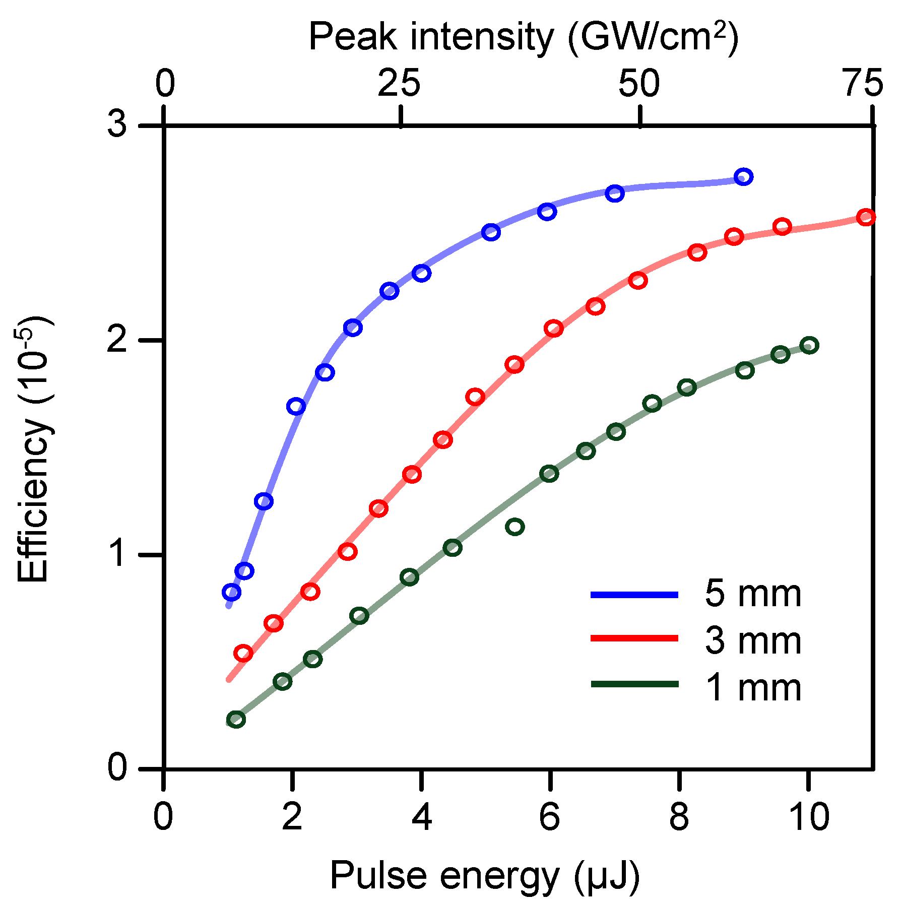
Figure 5 shows the optical-to-terahertz conversion efficiency (i.e., the ratio of the terahertz pulse energy to the pump pulse energy) as a function of the pump pulse energy for different thicknesses of the GaP generator crystal. For all crystal thicknesses, the efficiency at first grows linearly with the pump pulse energy and then starts to saturate. The linear efficiency growth corresponds to the second order of the nonlinear optical rectification process. The slope of the linear segment of the curves is steeper for thicker crystals because the size of the Cherenkov wedge is proportional to the terahertz generation length in the crystal, which is limited by the crystal thickness in the low pump energy regime. The proportionality of the slope to the crystal thickness is fulfilled rather well for the 3 and 5 mm thick crystals. For the 1 mm thick crystal, the slope is steeper than one could expect from the comparison with two other curves. This can be explained by a significant contribution of transient radiation generated at the crystal output face (
Figure 2) to the terahertz energy in the thin crystal, where the size of the Cherenkov wedge is small (
Figure 2). The saturation can be mainly attributed to the three-photon absorption of laser radiation. The maximum efficiency of ~
in
Figure 5 is much higher than the efficiency of the standard collinear scheme for the same pump. In fact, we could not detect any terahertz signal with the Golay cell after changing the experimental setup to the collinear scheme. Taking into account the Golay cell sensitivity, this means at least several tens of times lower efficiency than ~
. By using electro-optic sampling, about an order of magnitude lower efficiency (~
) was reported for the collinear scheme with a 2 mm thick GaP crystal and comparable pump intensity [
28].
Figure 6 shows the experimental waveforms (measured as a relative difference of signals of two photodiodes
,
Figure 4) and their spectra for two crystal thicknesses and different energies of the pump laser pulse. For the 1 mm thick crystal [
Figure 6a,b], the spectrum width and maximum position agree very well with the theoretical predictions [
Figure 3b]. However, the experimental waveforms differ significantly from the calculated ones [
Figure 3a]. This can be explained by the effect of focusing. Indeed, the electric field in focus is proportional to the time-derivative of the incident field [
29]. Taking this into account, the agreement between the experimental (focused) waveforms [
Figure 6a,c] and theoretical (unfocused) ones [
Figure 3a] becomes good.
For the 3 mm thick crystal [
Figure 6c,d], the signal is larger and the spectrum width is slightly smaller than for the 1 mm thick crystal. In
Figure 6d, one can observe the effect of spectrum narrowing with increasing the pump pulse energy predicted by numerical modeling [
Figure 3b].
For both crystals, the dependence of the electro-optic signal amplitude on the pump pulse energy agrees well with the energy measurements by the Golay cell (
Figure 5). Saturation of the amplitude growth in
Figure 6a,b is more pronounced for the thicker crystal, in accordance with the efficiency saturation in
Figure 5.

 ,
, 