Article

Thermal Sensitivity of Birefringence in Polarization-Maintaining Hollow-Core Photonic Bandgap Fibers

1
Key Laboratory of Materials for High Power Laser, Shanghai Institute of Optics and Fine Mechanics, Chinese Academy of Sciences, Shanghai 201800, China
2
Center of Materials Science and Optoelectronics Engineering, University of Chinese Academy of Sciences, Beijing 100049, China
3
Hangzhou Institute for Advanced Study, University of Chinese Academy of Sciences, No. 1, Sub-Lane Xiangshan, Xihu District, Hangzhou 310024, China
4
School of Electronic Science and Applied Physics, Hefei University of Technology, Hefei 230009, China
*
Author to whom correspondence should be addressed.
Photonics 2023, 10(2), 103; https://doi.org/10.3390/photonics10020103
Submission received: 11 December 2022 / Revised: 3 January 2023 / Accepted: 6 January 2023 / Published: 18 January 2023
(This article belongs to the Special Issue Optical Fiber Physical and Mechanical Sensors)

Abstract

:
Polarization-maintaining (PM) fiber is the core sensitive component of a fiber optic gyroscope (FOG); its birefringence temperature stability is crucial for maintaining accuracy. Here, we systematically investigated the structural thermal deformation and the resulting birefringence variation in typical PM hollow-core photonic bandgap fibers (HC-PBGFs) for FOG according to varying fiber structure parameters. To verify the application potential of PM HC-PBGFs in FOG, we compared the thermal sensitivity of birefringence (TSB) with that of the commonly used Panda PM fiber, which was tested to 5.07 × 10⁻⁵/100 °C. For rhombic-core fibers, the TSB was determined by the structure of the cladding and could be tuned as low as low as 10−7/100 °C, two orders of magnitude smaller than that of the panda PM fibers. For hexagonal-core fibers, the birefringence variation depended mainly on the drift of the surface modes (SMs) caused by the deformation of the core. A slight drift in SMs could cause a dramatic birefringence variation in hexagonal-core fiber, and the TSB could be as high as 10−4/100 °C, much higher than that of panda PM fiber. This study lays the foundation for the development of high birefringence temperature-stable HC-PBGFs and their applications in FOG.

1. Introduction

A fiber optic gyroscope (FOG) is an inertial navigation device based on the Sagnac effect [1,2]; it is compact and can provide precise rotational rate information with high reliability, high sensitivity, and a large dynamic range [3]. After decades of development, FOG has been successfully applied in various fields, including aircraft, satellite navigation, and attitude control [4,5,6,7,8]. The demand for highly stable FOG is growing in applications where the FOG is exposed to complex physical fields, because temperature fluctuations, magnetic fields, and irradiation result in additional non-reciprocal phase drift errors that degrade the stability of the FOG [9,10,11,12]. For a stable FOG, it is crucial to eliminate the effect of temperature fluctuations, which dominate among the factors that induce drift errors. The error caused by the temperature fluctuation of the FOG stems primarily from the temperature instability of the fiber, which originates from two aspects: optical path changes due to the thermo-optic and thermal expansion effects and birefringence changes caused by internal stress and structural deformation [13,14,15,16].
Hollow-core photonic bandgap fiber (HC-PBGF) FOG is a novel gyro technology that has emerged in the past ten years. Compared with the traditional panda polarization-maintaining (PM) FOG, it is considered to have excellent temperature stability and is the most promising for future FOG technology [17,18,19].
The development of HC-PBGF FOG to replace panda PM fiber FOG is currently taking longer than expected. The main reason is that research on the performance of PM HC-PBGFs related to FOG is probably insufficient. Compared with ordinary fibers, HC-PBGFs exhibit excellent temperature stability [17,20]. However, previous studies have mainly focused on the excellent optical path temperature stability caused by the extremely low thermo-optic effect of the air core [13,21,22]. Research on the thermal sensitivity of birefringence (TSB) of HC-PBGFs is rare. Wang et al. studied the thermal deformation and birefringence temperature characteristics of a rhombic-core fiber with a specific structure [14]. Ma et al. tested the birefringence of a circular-core fiber at different temperatures above 0 °C [23]. To date, regarding the TSB of HC-PBGFs, the following questions still need to be investigated: How does the thermal deformation of the fiber affect birefringence? What is the intrinsic relationship between the fiber structure design and the TSB? How can the temperature stability of the birefringence be improved through structural design? In this study, the thermal deformation and TSB of fibers in different structures were systematically investigated. Moreover, we tested the TSB of commonly used panda PM fiber and compared it with that of PM HC-PBGFs. The structural tuning mechanism of the HC-PBGFs on the TSB and the high-temperature stable fiber design are revealed, which provides an optimized solution for solving the temperature stability of the FOG.

2. Fiber Structure and Fundamental Properties

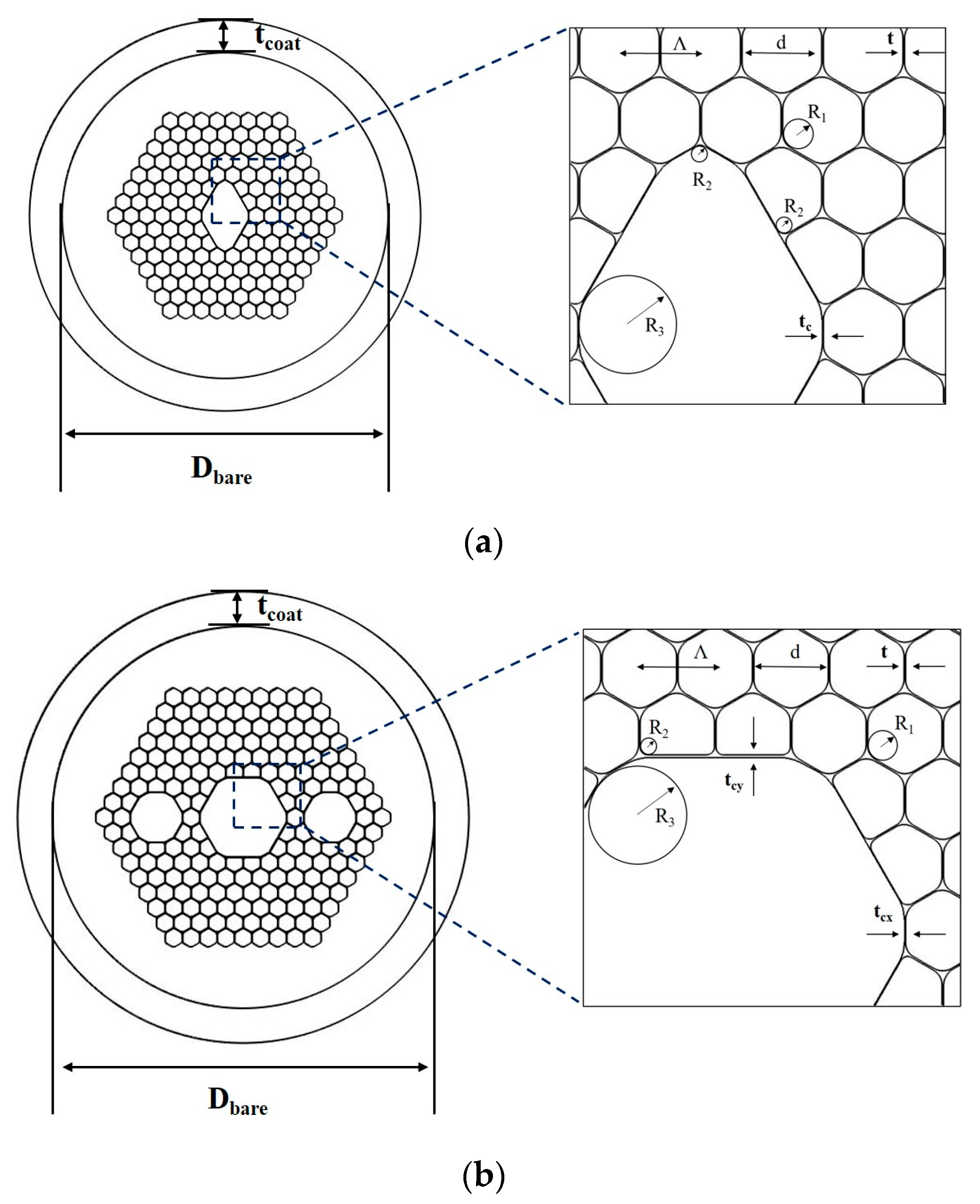
2.1. Fiber Structure

FOG has two developmental trends: miniaturization and high precision. Miniaturized FOG requires the fiber coils to be as small as possible and fabricated using a relatively thin-diameter fiber. High-precision FOG requires a sufficiently long fiber, which should result in relatively low loss; thus, the fiber will have a large core size.
The thin-diameter PM HC-PBGFs employ 9-cell rhombic cores, as shown in Figure 1a. The diameter was investigated from 80 µm to 140 µm. The geometric asymmetry of the fiber core resulted in a difference in the propagation constants of the fundamental modes (FM) of X-polarization (X-p) and Y-polarization (Y-p), thereby introducing birefringence. This fiber is suitable for miniaturized FOG applications because the fiber coil volume can be reduced as much as possible.
The large-core-size PM HC-PBGFs investigated in this study employ a 19-cell hexagonal-core, as shown in Figure 1b. A large core reduces the overlap between the signal power and the glass wall surrounding the core, decreasing surface scattering and achieving low loss [24]. The birefringence of this fiber arises from surface modes (SMs) drift. The thickness of the horizontal core wall differs from that of the vertical core wall. Therefore, the SMs in the X and Y directions have varying anti-crossing coupling points with the FMs. When one FM is coupled, the effective refractive index, neff, of this mode increases near the coupling point, resulting in a high birefringence.
Several parameters are used to describe the fiber structure. The cladding consists of a periodic rounded hexagonal structure with a lattice spacing Λ, an air pore diameter d, a wall thickness, t, between air pores which is equal to (Λ-d), and a pore fillet radius of the cladding and first cladding ring of R1 = 0.23Λ and R2 = 0.11Λ, respectively. The rhombic-core fiber has a core wall thickness of tc = 0.5 t to avoid the distribution of SMs [25]. The corner radius of core are R2 = 0.11Λ and R3 = 0.6Λ, as shown in Figure 1a. For a rhombic-core fiber, this study investigated the TSB under different cladding air-filling ratios, mainly characterized by d/Λ. The hexagonal-core fiber has core wall thickness of tcx and tcy in horizontal and vertical directions, respectively. The corner radius of the core is R3 = 0.6Λ, as shown in Figure 1b. For hexagonal-core fibers, the TSB was investigated at different core wall thicknesses because of the SMs, where tcx was fixed at 0.5 t and the vertical tcy varied. In addition, the thickness of the quartz fiber layer was characterized by the bare fiber diameter, Dbare, and the coating thickness, tcoat.

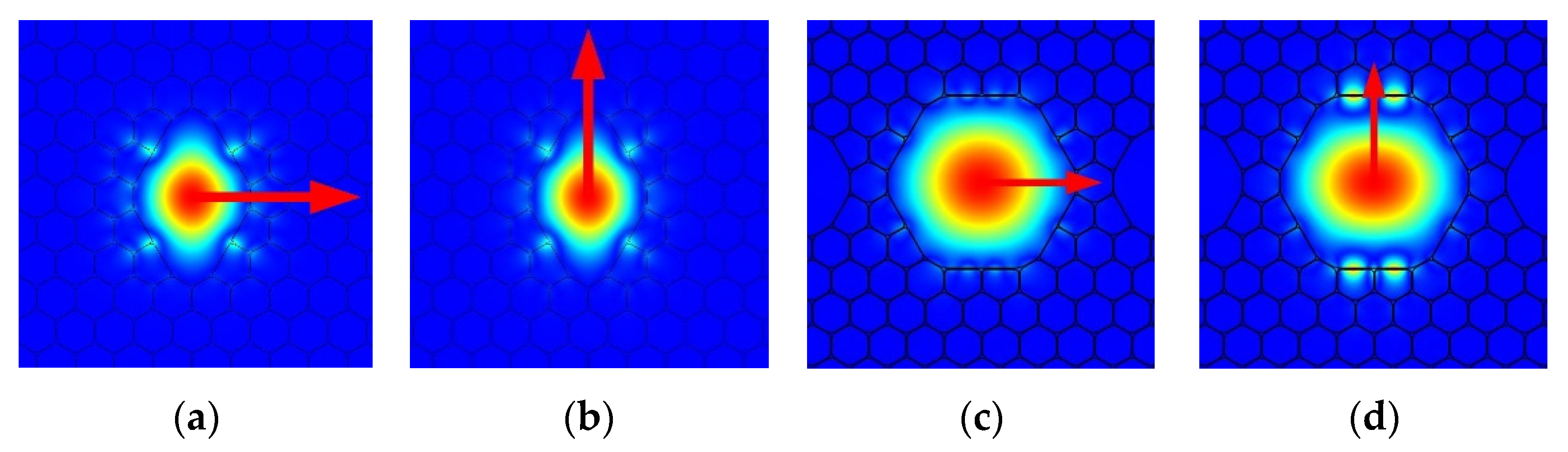
2.2. Fundamental Properties

Comsol software, based on the finite element method was employed for computations and exploring the fiber properties. The perfect matching layer was introduced as the boundary condition to calculate the effective index of FMs. Figure 2 shows the FMs of X-p and Y-p for rhombic and hexagonal fibers.
The imaginary part of the effective refractive index was used to calculate the confinement loss. Most of the fibers in this paper had confinement loss as less than 0.1 dB/km at 1550 nm, although the rhombic-core fiber with d/Λ = 0.97 had a higher confinement loss, 3.2 dB/km, making it suitable for low-precision FOG.
The difference between real parts of the effective refractive index of the two polarized FMs indicates the birefringence; it can be calculated using the following equation.
B = | Re ( n e f f x n e f f y ) |
The birefringence of the fibers with different d/Λ values at room temperature (20 °C) at 1550 nm is shown in Table 1. Here, the coating thickness was set to tcoat = 0 μm, because the stress from the quartz-coating surface can be ignored at room temperature. The fiber diameter was set to Dbare = 80 μm. When d/Λ was greater than 0.98, the birefringence was reduced to the order of 10−5, which is close to that of ordinary HC-PBGFs (6 × 10⁻⁵ [18]). Therefore, all the rhombic-core fibers in this study were still suitable for FOG.
Table 2 shows the birefringence value of the hexagonal core fiber with different tcy at room temperature at 1550 nm. Here, the fiber diameter was set to Dbare = 100 μm, and tcoat = 0 μm. The air-filling ratio d/Λ was 0.98, and the lattice spacing, Λ, was 5 μm. All the fibers shown in Table 2 exhibited birefringence in the order of 10−4, which was relatively large.

3. Thermal Sensitivity of Birefringence of HC-PBGFs

We combined solid mechanics and electromagnetic field modules of Comsol software to analyze the thermal deformation and optical modes of fibers. We defined TSB as the variation in birefringence, ΔB, per 100 °C; and the expression is shown in Equation (2). Here, we considered ΔT as a full temperature range (−40 °C to 60 °C).
TSB = Δ B Δ T
The TSB of the HC-PBGFs is originated from the deformation of the microstructure. First, the structural deformation and the resulting changes in birefringence were discussed. Subsequently, how the design of different microstructures, glass layers, and coating thicknesses affect the fiber thermal deformation, and in turn the TSB, was discussed.

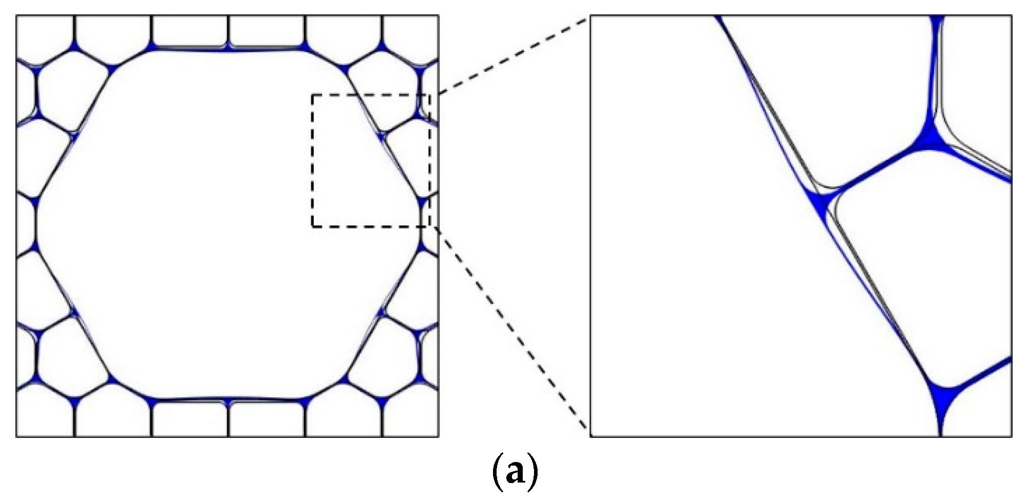
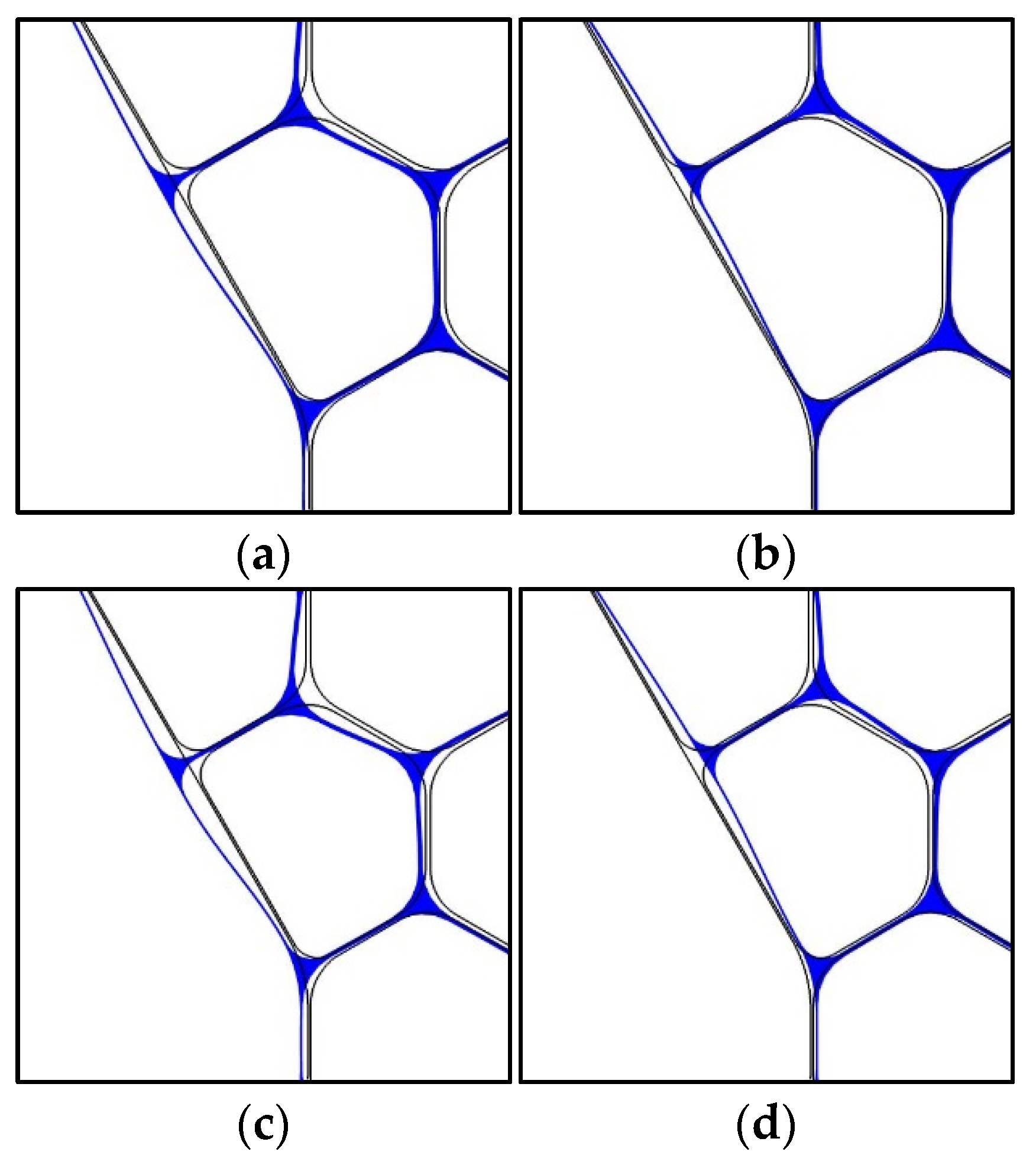
3.1. Thermal Deformation and Birefringence Variation in PM HC-PBGFs with Given Structure Parameters

When the fiber structure is fixed, the core expands gradually as the temperature increases. Figure 3a,b show the schematic diagrams of the deformation of the rhombic-core fiber at −40 °C and 60 °C (full-temperature range), respectively. In Figure 3, the grey lines represent the original structure of the fiber and the blue lines represent the thermal deformation structure, which is also applicable in other figures. In order to express the fiber deformation more clearly, the magnification of the deformation diagram of all fibers depicted in this paper is 10 times the original deformation. The fiber selected here had geometry parameter of d/Λ = 0.98, Dbare = 80 μm, and tcoat = 20 μm.
The displacement of point A, selected from the middle of upper right side of the original rhombic-core structure, was used to describe the deformation, as shown in Figure 3c. A’ is the point after displacement of A, and we took the displacement coming from expansion as the positive direction. The total deformation of the point A was about 0.057 μm, as the temperature varied from −40 °C to 60 °C. The quantitative relation curves between TSB and full-temperature variation are shown in Figure 3d. Similarly, the displacement of points A1, selected in the middle of upper right side of the original rhombic-core was used to describe the structure deformation. A1′ was the points after displacement of A. When d/Λ = 0.98, TSB varied from 8.73 × 10⁻⁶/100 °C to 8.86 × 10⁻⁶/100 °C with structural deforming from 0.010 μm to 0.045 μm, which showed a positive relationship. Figure 3e shows the variation in birefringence and neff of two polarized modes as a function of temperature. The birefringence curve has been linearly fitted with temperature. As the temperature increased, the roundness and symmetry of the fiber also increased. Birefringence should have reduced from an appearance point of view, but it had increased. The analysis showed that the increase in birefringence was due to the combination of both core and cladding lattice structure. As the temperature increased, in addition to core, the cladding lattice structure also deformed, which also affected mode propagation constant. This resulted in a growing disparity in the neff values of the two polarized FMs, thus increasing birefringence.
Figure 4a,b show the deformation of hexagonal-core fiber at −40 °C and 60 °C, respectively. The fiber selected here had the geometry parameters of d/Λ = 0.98, tcx = 0.5 t, tcy = 1.82 t, Dbare = 100 μm, and tcoat = 20 μm. Similar to rhombic-core fiber, the core asymmetry of hexagonal-fiber also decreased as temperature varied from −40 °C to 60 °C.
The displacement of point B, selected from the middle of upper right side of the original hexagonal-core structure, was used to describe the deformation, as shown in Figure 4c. B’ was the point after displacement of B, and we took the displacement coming from expansion as the positive direction. The total deformation of the point B was approximately 0.039 μm as the temperature varied from −40 °C to 60 °C. The quantitative relation curves between TSB and full-temperature variation are shown in Figure 4d. Similarly, the displacement of points B1, selected in the middle of upper right side of the original hexagonal cores was used to describe the structure deformation. B1′ was the points after displacement of B1. When d/Λ = 0.98, tcx = 0.5 t, tcy = 1.82 t, the TSB variation was complicated because of the surface modes drift. TSB reached the maximum value of 3.12 × 10⁻⁶/100 °C with the full-temperature deformation about 0.017 μm.
Figure 4e shows the variation of birefringence and neff of two polarized modes as a function of temperature at 1550 nm. During the temperature increase process, both the core shape and the lattice spacing deformed, which resulted in a growing disparity in the neff values of the two polarized FMs. The curve of the fiber’s birefringence varied with temperature, unlike the rhombic-core fiber, which exhibited a nonlinear trend. When the temperature gradually increased from 40 °C to 60 °C, the curves of the two polarized modes showed an increasing trend, whereas the slope of the X-p neff curve decreased. This tended to flatten the birefringence curve. The neff is determined by the deformation of both core and cladding. In hexagonal-core fiber, as temperature increased, the thermal expansion occurred in both core and the side holes, causing squeeze of the two, which limiting the further deformation of fiber core and first cladding ring in X dimension, thereby deformation gradually decrease. The neff of X-p mode was strongly related to the structure in X-dimension. Therefore, the change of neff with temperature and slope of its curve gradually decreased.

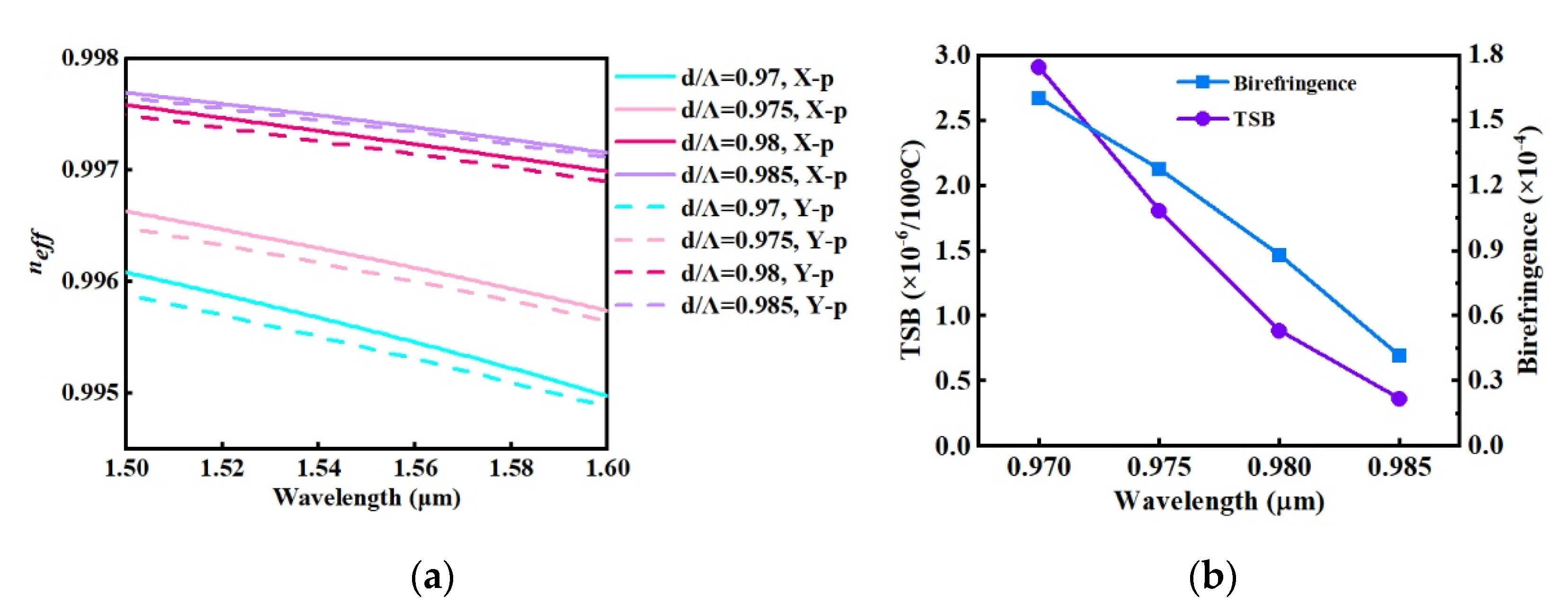
3.2. TSB of PM HC-PBGFs with Different Structure Parameters

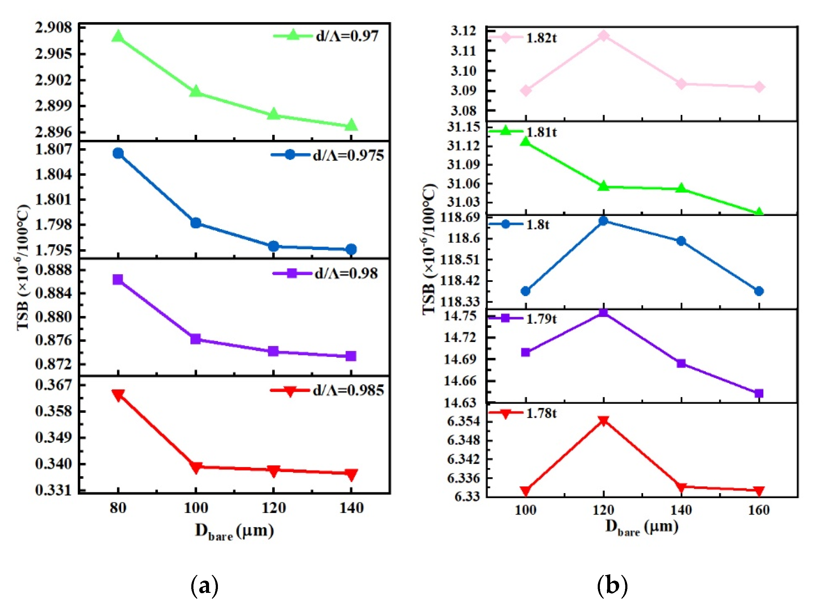
3.2.1. Different Periodic Microstructure Parameters

The birefringence of the rhombic-core fiber was mainly related to the asymmetry of the core size. In the X and Y dimensions, the core size was approximately Dx = 3Λ and Dy = 4.61Λ − 1.15 t, respectively. When d/Λ changed, to ensure that 1550 nm was located in the center of the band gap, the lattice spacing, Λ, and wall thickness, t, were adjusted. Thus, the core asymmetry and birefringence changed correspondingly. The birefringence and TSB at 1550 nm for rhombic-core fibers with different d/Λ parameters (Dbare = 80 μm, tcoat = 10 μm) are discussed. Figure 5a shows the neff of FM in rhombic fibers which have different d/Λ parameters. Figure 5b shows the TSB and birefringence of FM in rhombic-core fibers. As d/Λ increases, the birefringence shows a decreasing trend, because the difference of neff between X-p and Y-p reduces. The TSB also becomes smaller when d/Λ increasing. Therefore, a balance needs to be achieved. Here, we found that when d/Λ = 0.98, the birefringence was relatively large, 8.79 × 10⁻⁵, and the TSB was small, 8.86 × 10⁻⁷/100 °C.
The birefringence of the hexagonal-core fiber is formed by the anti-crossing of the SMs in the core wall and FM in the core; the anti-crossing point drifts under different core wall thicknesses, causing the birefringence to fluctuate. Figure 6a depicts the neff curves under different tcy values (Dbare = 100 μm, tcoat = 10 μm). The anti-crossing point of the X-p FM and SMs moves to the long wavelength as tcy changes from 1.78 t to 1.8 t; moreover, the neff of the X-p FM becomes higher and the slope of neff to the curve becomes larger at 1550 nm. Even a slight drift in the anti-crossing point from structural deformation leads to dramatic changes in birefringence and, therefore, increased thermal sensitivity. When tcy changes from 1.8 t to 1.82 t, the anti-crossing point gradually moves away from 1550 nm, and the slope of the neff curve and TSB decreases. Figure 6b shows the birefringence and TSB of hexagonal-core fibers under different tcy values. As predicted, the greatest slope of the neff curve at tcy = 1.8 t led to the maximum TSB, 1.18 × 10⁻⁴/100 °C. When tcy was far from 1.8 t, the anti-crossing point moved away from 1550 nm, the slope of the neff curve became gentle, the change in birefringence from core deformation became smaller, and the TSB could be reduced to 3.09 × 10⁻⁷/100 °C (tcy = 1.82 t), or even smaller.

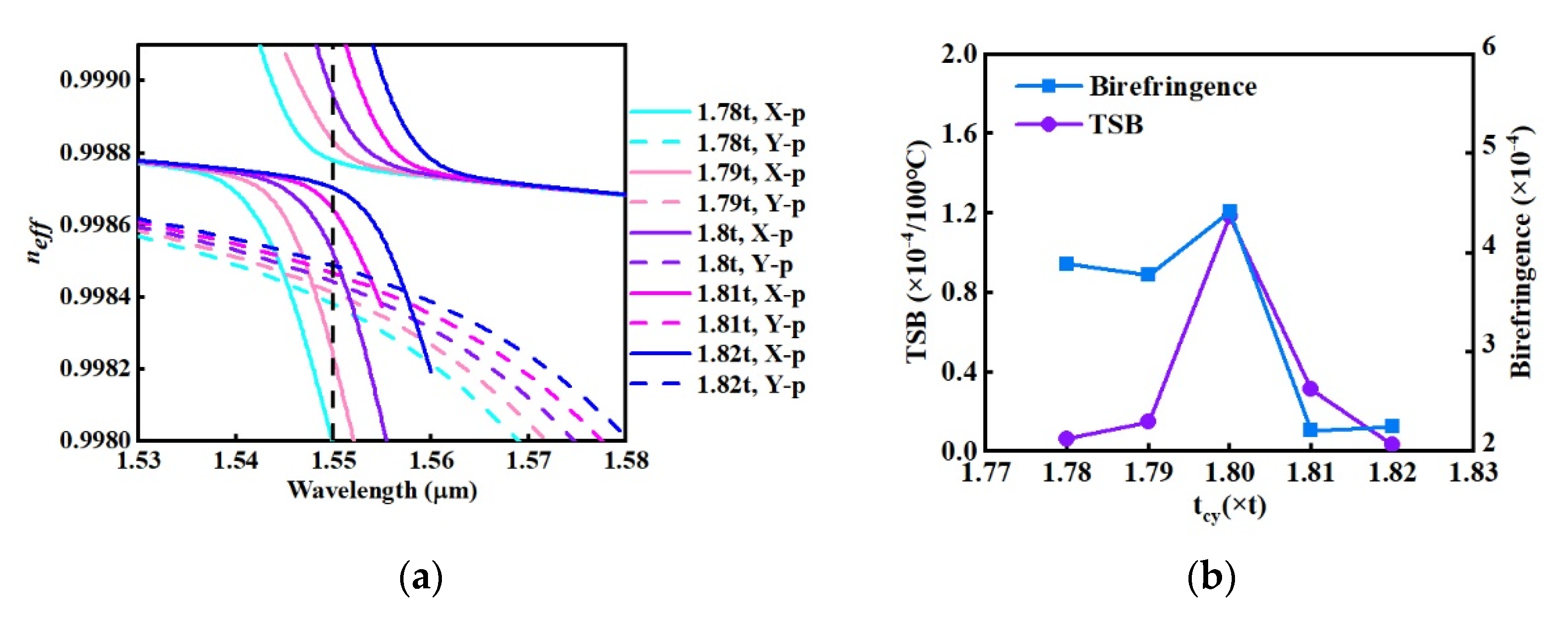
3.2.2. Different Glass Layer Thicknesses Parameters

In actual HC-PBGFs, quartz and coating layers outside the microstructure cladding are required to ensure the mechanical strength of the fiber. However, different thermal expansion rates α between the quartz layer and the coating layer (α of the quartz layer was 5.5 × 10⁻⁶ K−1, whereas that of the coating was 80 × 10−5 K−1 [21]) created an interaction force on the quartz-coating surface. The force could be transmitted to the microstructure, causing additional deformation and changes in birefringence. According to Fokoua et al. [13], when the thickness of the glass layer is large, the optical fiber can better resist external tensile force, ensuring that the fibers maintain their original shape in the longitudinal direction. The transverse structural deformation of fibers with varying quartz layer thicknesses and the resulting changes in the birefringence were investigated in this study.
Figure 7 shows the deformation of rhombic-core fibers with different quartz layer thicknesses at −40 °C and 60 °C. Here, the other structural parameters of the fiber remained unchanged: d/Λ = 0.98, tcoat = 10 μm. The thickness of the quartz layer was replaced by the diameter of the bare fiber, Dbare. There were significant differences in the thermal deformation of the fiber when Dbare was 80 μm and 140 μm. The greater the thickness of the quartz layer, the smaller the structural thermal deformation, which is also applicable for rhombic-core fibers with other microstructural parameters, as well as hexagonal-core fibers. Therefore, a thicker quartz layer surrounding the hollow microstructure provides effective resistance to pressure from the quartz-coating surface.
Figure 8a shows the TSB for rhombic-core fibers with different d/Λ parameters and quartz layer thicknesses (tcoat = 10 μm). When Dbare was greater than 120 μm, the quartz layer could sufficiently resist the pressure on the quartz-coating surface; therefore, the thermal deformation of the fiber was negligible, and the birefringence tended to be temperature-stable. Figure 8b shows the TSB for hexagonal-core fibers with different tcy values and quartz layer thicknesses (tcoat = 10 μm). Under different Dbare values, thermal deformation caused the neff curves of X-p and Y-p FM to shift to different extents, resulting in no discernible trend in birefringence variation. In general, when Dbare was larger than 140 μm, the TSB decreased. Therefore, for the hexagonal-core fiber in this study, the Dbare of the fiber was designed to be greater than 140 μm to improve the temperature stability of birefringence.

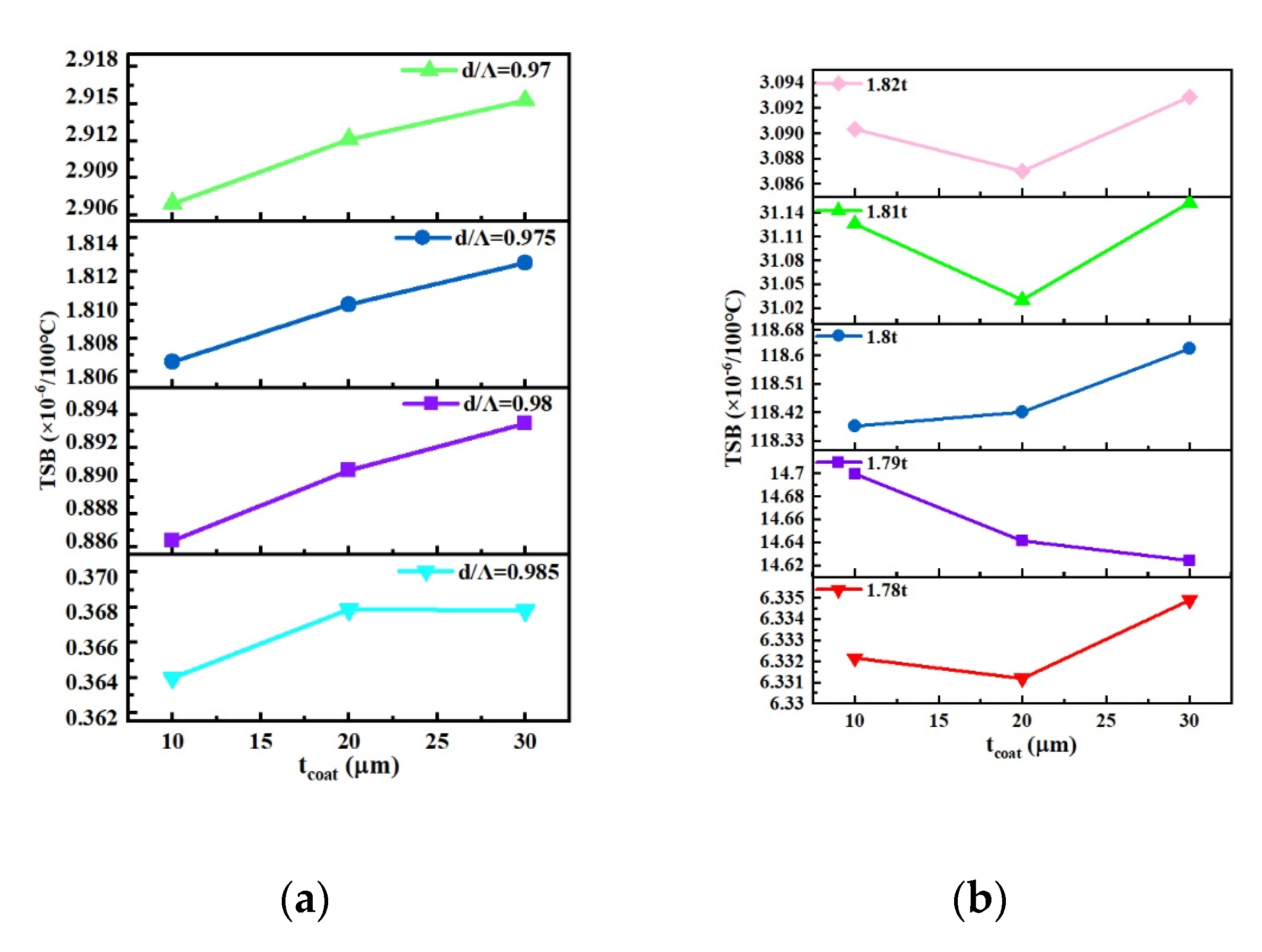
3.2.3. Different Coating Thickness

Interaction forces are created at the interface between the quartz layer and the coating because of the difference in their thermal expansion rates; the thicker the coating, the more obvious the effect. Figure 9 shows the deformation of rhombic-core fibers with different coating thicknesses at −40 °C and 60 °C. Here, the other structural parameters of the fiber remained unchanged: d/Λ = 0.98, Dbare = 80 μm. There were significant differences in the thermal deformation of the fiber when the coating thicknesses were 10 μm and 30 μm. The greater the thickness of the coating layer, the larger the thermal deformation of the structure, which is also applicable for rhombic-core fibers with other microstructural parameters and hexagonal-core fibers. Therefore, a thicker coating surrounding the bare fiber offers additional pressure.
Figure 10a shows the TSB of rhombic-core fibers with different d/Λ values and coating thicknesses (Dbare = 80 μm). The TSB roughly increased with the coating thickness; thus, the TSB improved. Figure 10b shows the TSB of hexagonal-core fibers with different core wall thicknesses tcy and coating thicknesses (Dbare = 100 μm). Under different tcoat values, the thermal deformation caused the neff curves of X-p and Y-p FM to shift to different extents. Therefore, the birefringence variation exhibited no apparent trend. In general, when tcoat was located at 20 μm, the TSB tended to decrease.

4. Comparison of TSB between PM HC-PBGFs and Panda PM Fiber

To verify the application potential of PM HC-PBGFs in improving the stability of FOG, we compared it with the widely used panda PM fiber for FOG. The thermal birefringence variation in the panda PM fiber was tested. Figure 11 shows a schematic diagram of the experimental setup, with a white-light interferometer, which was used to test the TSB of the fiber. The panda PM fiber was obtained from Corning (PM15-U25A).
Due to the lack of low temperature condition, the TSB of panda PM fiber was roughly estimated using the data measured in high temperature environment. In order to make the birefringence variation more obvious and facilitate the measurement, the selected temperature range was large, from 15 °C to 350 °C. The birefringence variation results to temperature is shown in Figure 12, and the average TSB of the panda PM fiber is approximately 5.07 × 10⁻⁵/100 °C.
Table 3 presents the TSB of PM HC-PBGFs under various fiber structures assessed in this study. The maximum sensitivity of the hexagonal-core HC-PBGFs was 1.19 × 10⁻⁴/100 °C, and the birefringence stability of this fiber is weaker than that of the panda PM fiber. Through structural design, the sensitivity could be reduced to the order of 3.12 × 10⁻⁶/100 °C, which was one order of magnitude smaller than that of panda PM fiber. The birefringence was more stable as the core wall thickness, tcy, changed to keep 1550 nm away from the anti-crossing point. The TSB of rhombic-core fiber was the highest at 2.92 × 10⁻⁶/100 °C, which could be reduced to 3.4 × 10⁻⁷/100 °C through structural design, demonstrating its superiority.

5. Conclusions

To meet the requirements of miniaturized and high-precision FOG applications, the thermal-induced structural deformation and TSB of two PM HC-PBGFs, rhombic-core and hexagonal-core fibers, were studied systematically. The birefringence variations in PM HC-PBGFs is mainly originated from structure deformation. As the temperature increased, the core asymmetry of both types of fiber tended to decrease due to thermal expansion, whereas the birefringence increased because of the influence of cladding deformation. Structural deformation is correlated with the fiber structural design which also determines the fiber TSB. To verify the application potential of PM HC-PBGFs in FOG, the TSB of the panda PM fiber was tested, which is 5.07 × 10⁻⁵/100 °C. For rhombic-core fibers, the TSB was mainly optimized by the cladding structural design and could be tuned to two orders of magnitude smaller than that of the panda PM fiber. For hexagonal-core fibers, the TSB was sensitive to the core wall thickness, tcy, and could go as high as 1.18 × 10⁻⁴/100 °C if tcy was intended to move anti-crossing point close to 1550 nm. In addition, due to the thermal effects, thick quartz layers help to resist deformation from external stress, whereas thin coatings have the opposite effect. Increasing the thickness of the quartz layer of the rhombic-core fiber, and reducing the thickness of the coating layer, can further reduce the TSB. Therefore, tuning the structure parameters of PM HC-PBGFs can result in the TSB being larger or far smaller than that of panda PM fiber. The thermal deformation of each part of the fiber structure and its specific effect on the effective refractive index will be further quantified in future work. In addition, the birefringence high-temperature stability design theory of HC-PBGF will also be used to guide the fabrication of optical fibers. This study revealed the correlation between the temperature stability of fiber birefringence and structural design, providing a theoretical basis for controlling the temperature stability of HC-PBGFs.

Author Contributions

Conceptualization, L.W. and M.L.; methodology, L.W. and W.L.; software, L.W., W.L. and J.X.; validation, L.W. and F.Y.; formal analysis, L.W. and F.Y.; investigation, L.W.; resources, M.L. and L.H.; data curation, L.W.; writing—original draft preparation, L.W.; writing—review and editing, L.W., M.L., F.Y. and W.G.; supervision, M.L. All authors have read and agreed to the published version of the manuscript.

Funding

This research was funded by the National Natural Science Foundation of China (NSFC) (51972317, 61905258); the Key Program for International S&T Cooperation Projects of China (2018YFE0115600); and the Special Project for Industrialization of High-Tech Science and Technology between Jilin Province and the Chinese Academy of Sciences (2021SYHZ0029).

Institutional Review Board Statement

Not applicable.

Informed Consent Statement

No applicable.

Data Availability Statement

Data underlying the results presented in this paper are not publicly available at this time but may be obtained from the authors upon reasonable request.

Acknowledgments

In this section, you can acknowledge any support given which is not covered by the author contribution or funding sections. This may include administrative and technical support, or donations in kind (e.g., materials used for experiments).

Conflicts of Interest

The authors declare no conflict of interest.

References

  1. Post, E.J. Sagnac effect. Rev. Mod. Phys. 1967, 39, 475–494. [Google Scholar] [CrossRef]
  2. Arditty, H.J.; Lefèvre, H.C. Sagnac effect in fiber gyroscopes. Opt. Lett. 1981, 6, 401–403. [Google Scholar] [CrossRef] [PubMed]
  3. Zhao, S.X.; Liu, Q.W.; Liu, Y.Y.; Hui, H.L.; He, Z.Y. Navigation-grade resonant fiber-optic gyroscope using ultra-simple white-light multibeam interferometry. Photonics Res. 2022, 10, 542–549. [Google Scholar] [CrossRef]
  4. Lefèvre, H.C.; Steib, A.; Claire, A.; Couderette, A.; Pointel, A.-L.; Viltard, A.; Bonnet, A.; Frénois, A.; Gandoin, A.; Laurent, A.; et al. The fiber optic gyro ‘adventure’ at Photonetics, iXsea and now iXblue. SPIE Defense + Commercial Sensing. Opt. Waveguide Laser Sens. 2020, 11405, 791. [Google Scholar] [CrossRef]
  5. Pavlath, G.A. Fiber Optic Gyros: The Vision Realized. In Proceedings of the Optical Fiber Sensors, Cancun, Mexico, 23–27 October 2006. [Google Scholar]
  6. Zarinetchi, F.; Ezekiel, S. Observation of lock-in behavior in a passive resonator gyroscope. Opt. Lett. 1986, 11, 401–403. [Google Scholar] [CrossRef]
  7. Jin, J.; Zhang, T.; Kong, L.; Ma, K. In-Orbit Performance Evaluation of a Spaceborne High Precision Fiber Optic Gyroscope. Sensors 2018, 18, 106. [Google Scholar] [CrossRef] [Green Version]
  8. Digonnet, M.J.; Chamoun, J.N. Recent developments in laser-driven and hollow-core fiber optic gyroscopes. In Proceedings of the Fiber Optic Sensors and Applications XIII, Baltimore, MD, USA, 12 May 2016. [Google Scholar]
  9. Böhm, K.; Petermann, K.; Weidel, E. Sensitivity of a fiber-optic gyroscope to environmental magnetic fields. Opt. Lett. 1982, 7, 180–182. [Google Scholar] [CrossRef]
  10. Du, S.; Wang, X.; Lin, S.; Zhang, C. Gamma-radiation induced degradation random walk error in interferometer fiber optic gyroscope. Opt. Appl. 2011, 41, 953–959. [Google Scholar]
  11. Ma, H.; Yan, Y.; Chen, Y.; Jin, Z. Improving long-term stability of a resonant micro-optic gyro by reducing polarization fluctuation. IEEE Photon. J. 2012, 4, 2372–2381. [Google Scholar]
  12. Choi, W.S. Analysis of temperature dependence of thermally induced transient effect in interferometric fiber-optic gyroscopes. J. Opt. Soc. Korean 2011, 15, 237–243. [Google Scholar] [CrossRef] [Green Version]
  13. Fokoua, E.N.; Petrovich, M.N.; Bradley, T.; Poletti, F.; Richardson, D.J.; Slavík, R. How to make the propagation time through an optical fiber fully insensitive to temperature variations. Optica 2017, 4, 659. [Google Scholar] [CrossRef] [Green Version]
  14. Wang, C.G.; She, X.; Chen, K.; Yang, Z.; Chen, X.F.; Huang, T.C.; Liu, C. Analysis of thermal property in hollow-core polarization maintaining photonic crystal fibers. Opt. Rev. 2017, 24, 291–296. [Google Scholar] [CrossRef]
  15. Varnham, M.; Payne, D.; Barlow, A.; Birch, R. Analytic Solution for the Birefringence Produced by Thermal Stress in Polarization-Maintaining Optical Fibers. J. Light. Technol. 1983, LT-1, 332–339. [Google Scholar] [CrossRef] [Green Version]
  16. Rashleigh, S. Origins and control of polarization effects in single-mode fibers. J. Light. Technol. 1983, 1, 312–331. [Google Scholar] [CrossRef]
  17. Digonnet, M.J.F.; Kim, H.K.; Blin, S.; Dangui, V.; Kino, G.S. Sensitivity and Stability of an Air-Core Fiber Gyroscope. In Proceedings of the Optical Fiber Sensors, Cancun, Mexico, 23–27 October 2006. [Google Scholar]
  18. Kim, H.K.; Digonnet, M.J.F.; Kino, G.S. Air-Core Photonic-Bandgap Fiber-Optic Gyroscope. J. Light. Technol. 2006, 24, 3169. [Google Scholar]
  19. Zhang, Z.; Wang, Y.Y.; Zhou, M.; He, J.; Liao, C.R.; Wang, Y.P. Recent advance in hollow-core fiber high-temperature and high-pressure sensing technology. Chin Opt Lett. 2021, 19, 070601. [Google Scholar] [CrossRef]
  20. Blin, S.; Kim, H.K.; Digonnet, M.J.F.; Kino, G.S. Reduced Thermal Sensitivity of a Fiber-Optic Gyroscope Using an Air-Core Photonic-Bandgap Fiber. J. Light. Technol. 2007, 25, 861–865. [Google Scholar] [CrossRef]
  21. Dangui, V.; Kim, H.K.; Digonnet, M.J.F.; Kino, G.S. Phase sensitivity to temperature of the fundamental mode in air-guiding photonic-bandgap fibers. Opt. Express 2005, 13, 6669–6684. [Google Scholar] [CrossRef]
  22. Slavík, R.; Marra, G.; Fokoua, E.N.; Baddela, N.; Wheeler, N.V.; Petrovich, M.; Poletti, F.; Richardson, D.J. Ultralow thermal sensitivity of phase and propagation delay in hollow core optical fibres. Sci. Rep. 2015, 5, 15447. [Google Scholar] [CrossRef] [Green Version]
  23. Ma, H.H.; Liu, D.N.; Feng, C.K.; Feng, L.S. Thermal sensitivity of the birefringence of photonic-bandgap fiber. In Proceedings of the Applied Optics and Photonics China 2021, Beijing, China, 24 November 2021. [Google Scholar]
  24. Petrovich, M.N.; Poletti, F.; Brakel, A.V.; Richardson, D.J. Robustly single mode hollow core photonic bandgap fiber. Opt. Express 2008, 16, 4337–4346. [Google Scholar] [CrossRef]
  25. Amezcua-Correa, R.; Broderick, N.G.R.; Petrovich, M.N.; Poletti, F.; Richardson, D.J. Design of 7 and 19 cells core air-guiding photonic crystal fibers for low-loss, wide bandwidth and dispersion controlled operation. Opt. Express 2007, 15, 17577–17586. [Google Scholar] [CrossRef] [PubMed]
Figure 1. Transverse geometry of (a) rhombic-core fiber and (b) hexagonal-core fiber.
Photonics 10 00103 g001
Figure 2. (a) FM of X-p for rhombic-core fiber (b) FM of Y-p for rhombic-core fiber (c) FM of X-p for hexagonal-core fiber (d) FM of Y-p for hexagonal-core fiber.
Photonics 10 00103 g002
Figure 3. (a) Thermal deformation of rhombic-core fiber at −40 °C (b) Thermal deformation of rhombic-core fiber at 60 °C (c) Structural deformation in rhombic-core fiber as a function of temperature (d) TSB variation with full-temperature deformation of rhombic-core fiber (e) Change in birefringence of rhombic-core fiber with temperature.
Photonics 10 00103 g003
Figure 4. (a) Thermal deformation of hexagonal-core fiber at −40 °C (b) Thermal deformation of hexagonal-core fiber at 60 °C (c) Structural deformation of hexagonal-core fiber as a function of temperature (d) TSB variation with full-temperature deformation of hexagonal-core fiber (e) Change of birefringence in hexagonal-core fiber with temperature.
Photonics 10 00103 g004aPhotonics 10 00103 g004b
Figure 5. (a) neff of rhombic-core fiber with different d/Λ parameters (b) Birefringence and TSB of rhombic-core fiber with different d/Λ parameters.
Photonics 10 00103 g005
Figure 6. (a) Anti-crossing curves of quasicircular core fiber with different tcy parameters (b) Fiber birefringence and TSB under different tcy parameters.
Photonics 10 00103 g006
Figure 7. (a) Deformation of rhombic-core fiber at −40 °C with Dbare = 80 μm (b) Deformation of rhombic-core fiber at 60 °C with Dbare = 80 μm (c) Deformation of rhombic-core fiber at −40 °C with Dbare = 140 μm (d) Deformation of rhombic-core fiber at 60 °C with Dbare = 140 μm.
Photonics 10 00103 g007
Figure 8. (a) TSB of rhombic-core fiber under different Dbare parameters (b) TSB of hexagonal-core fiber under different Dbare parameters.
Photonics 10 00103 g008
Figure 9. (a) Deformation of rhombic-core fiber at −40 °C with tcoat = 10 μm (b) Deformation of rhombic-core fiber at 60 °C with tcoat = 10 μm (c) Deformation of rhombic-core fiber at −40 °C with tcoat = 30 μm (d) Deformation of rhombic-core fiber at 60 °C with tcoat = 30 μm.
Photonics 10 00103 g009
Figure 10. (a) TSB of rhombic-core fiber with different tcoat parameters (b) TSB of hexagonal core fiber with different tcoat parameters.
Photonics 10 00103 g010
Figure 11. Setup for measurement of fiber birefringence by white light interferometry.
Photonics 10 00103 g011
Figure 12. Birefringence variation of panda PM fiber with temperature.
Photonics 10 00103 g012
Table 1. Birefringence of rhombic-core fiber at room temperature (20 °C).
d/Λ0.970.9750.980.985
Birefringence1.6 × 10−41.28 × 10−48.79 × 10−54.15 × 10⁻⁵
Table 2. Birefringence of hexagonal-core fiber at room temperature (20 °C).
tcy1.78 t1.79 t1.8 t1.81 t1.82 t
Birefringence3.88 × 10−43.77 × 10−44.41 × 10−42.21 × 10−42.25 × 10−4
Table 3. Thermal sensitivity of birefringence of fiber in different parameters.
Fiber TypesGeometry ParametersTSB
Panda PM fiberDcore = 8.5 µm, Dbare = 125 µm5.07 × 10−5/100 °C
Rhombic core fiberd/Λ (Dbare = 80 μm, tcoat = 30 μm)0.972.92 × 10−6/100 °C
0.9751.81 × 10−6/100 °C
0.988.93 × 10−7/100 °C
0.9853.68 × 10−7/100 °C
Hexagonal core fibertcy (Dbare = 120 μm, tcoat = 10 μm)1.78 t6.36 × 10−6/100 °C
1.79 t1.48 × 10−5/100 °C
1.8 t1.19 × 10−4/100 °C
1.81 t3.11 × 10−5/100 °C
1.82 t3.12 × 10−6/100 °C
Disclaimer/Publisher’s Note: The statements, opinions and data contained in all publications are solely those of the individual author(s) and contributor(s) and not of MDPI and/or the editor(s). MDPI and/or the editor(s) disclaim responsibility for any injury to people or property resulting from any ideas, methods, instructions or products referred to in the content.

