Article

Asymptotic Capacity Maximization for MISO Visible Light Communication Systems with a Liquid Crystal RIS-Based Receiver

National Digital Switching System Engineering and Technological Research Center, Zhengzhou 450000, China
*
Author to whom correspondence should be addressed.
Photonics 2023, 10(2), 128; https://doi.org/10.3390/photonics10020128
Submission received: 1 December 2022 / Revised: 30 December 2022 / Accepted: 6 January 2023 / Published: 27 January 2023
(This article belongs to the Special Issue Advances in Visible Light Communication)

Abstract

:
Combined with reconfigurable intelligent surfaces (RISs), visible light communications (VLCs) can increase the communication performance to a great degree. However, the research into RIS-aided VLC systems has mainly focused on mirror array-based RISs deployed on the wall while neglecting liquid crystal (LC)-based RISs in VLC receivers. With the development of advanced materials, the LC RIS has been gradually attracting attention from researchers. Inspired by the current research into the LC RIS, the applications of the LC RIS in multiple-input single-output (MISO) VLC systems are investigated in this paper. We formulate an optimization problem with asymptotic capacity maximization as the objective function and the refractive index of the LC RIS as the independent variable. As for this nonconvex optimization problem, we propose the particle swarm optimization (PSO) algorithm to determine the configuration of parameters for the LC RIS. The simulation results indicate that the employment of the LC RIS in VLC receivers can raise the communication performance of the MISO-VLC systems; meanwhile, the proposed algorithm is an effective way to deal with the optimization problems for LC RIS-based MISO-VLC systems when compared with the exhaustive search method and a baseline scheme. The LC RIS is also expected to solve the dead zone problem in traditional VLC systems.

1. Introduction

As candidate technologies for the upcoming sixth generation (6G) wireless communication, visible light communication (VLC) and reconfigurable intelligent surface (RIS) have been developed rapidly in recent years to address the shortcomings of the fifth generation (5G) wireless communication [1]. Specifically, VLC is able to provide a large amount of unlicensed bandwidth offering abundant communication resources to complement the scarcity of spectrum resources for radio frequency (RF) communications [2]. Meanwhile, VLC is considered an environmental and green communication technology due to its ability to achieve a communication process when the illumination need is satisfied. On the other hand, RIS is regarded as a prospective technology to enhance communication performance by its characteristic of manipulating the wireless propagation environment in an intelligent way in real time [3]. This is a prospective research direction, and the employment of RIS in RF communication has been investigated recently [4,5,6].
An RIS can be defined as a metasurface comprised of artificial meta-atoms or a mirror array composed of low-cost passive reflective elements. Simultaneously, an RIS controller is integrated into the technology to sense the environment, judge the changes in circumstance, and make adaptive decisions on the metasurface or mirror array in order to achieve the changes in the transmission environment intelligently [7,8]. In consideration of the potential of VLC and the ability of the RIS to enhance communication performance, combined with the technical bottleneck faced by VLC technology (e.g., high path loss, alignment issues with the transmitters and receivers, and high penetration loss [9]), RIS has been widely applied in VLC systems to obtain a performance gain in the communication process [10,11,12,13,14] and overcome the shortcomings of VLC [15,16]. The area of VLC RIS mentioned above has concentrated mainly on the part between the transmitter and the receiver, and the process is achieved by the mirror array-based VLC RIS deployed on walls, since the VLC RIS comprised of a mirror array exceeds a metasurface-based VLC RIS [17]. However, the research into liquid crystal (LC) RISs in VLC receivers for beam steering and light amplification is sparse and still in the initial stages. Based on the current research on LC RIS, this paper concentrates on the employment of an LC RIS in MISO-VLC systems to investigate the benefits LC RIS can bring.
In [18], the authors outlined the effectiveness of LC RIS in increasing the signal-to-noise ratio (SNR) and enhancing the field-of-view (FoV) in the receiver. With the existence of etendue reducers composed of convex lenses in traditional VLC receivers, combined with the reflection at the upper surface of the lens, the transmission process from the incident light to the photodetector (PD) can produce up to 30 % optical intensity losses [19]. The application of convex lenses in VLC receivers limits the transmission capabilities of VLC systems owing to the reflection process on the surfaces of lenses; consequently, some methods were examined in [20] to try to steer the incident light dynamically and amplify the incident light intensity simultaneously. Comparing various methods, the LC RIS is considered as a low-cost and robust method to overcome the drawbacks faced by traditional VLC receivers. Specifically, an external voltage is used to reorient the LC molecules to control the refractive index of the LC RIS. Consequently, the LC RIS is able to steer the incident light in the VLC receivers, tuning the refractive index dynamically. The work on realizing LC RIS-based VLC receivers in practical life was conducted in [21,22,23,24], and a practical design for an LC RIS was proposed in [25]. Inspired by the work in [25], we propose an LC RIS-based MISO-VLC system and formulate an optimization problem with asymptotic capacity maximization as the utility function. Our main contributions are as follows.
  • An LC RIS-aided MISO-VLC system is proposed with an LC RIS in the VLC receiver to steer the incident light dynamically; meanwhile, the corresponding asymptotic capacity in the MISO-VLC system is enhanced after applying the LC RIS;
  • For the LC RIS-aided MISO-VLC system, the asymptotic capacity in high SNR with peak-constrained inputs is derived. Additionally, we formulate an optimization problem with the asymptotic capacity derived by us as the objective function and the refractive index of LC RIS as the independent variable. For this nonconvex optimization problem, we propose a metaheuristic optimization algorithm (particle swarm optimization algorithm) to determine the optimal refractive index of the LC RIS according to the environmental changes;
  • The simulation results demonstrate that the employment of an LC RIS in VLC receivers can raise the communication performance of MISO-VLC systems to a greater degree. Simultaneously, compared with the exhaustive search method, the PSO algorithm is an effective method to deal with the optimization problems for LC RIS-based MISO-VLC systems. Meanwhile, we found that there was a significant performance gain compared with a benchmark scheme (BSch) (randomly selecting a refractive index of LC RIS) or the MISO-VLC systems with receivers without the LC RIS. In addition, the LC RIS is expected to solve the dead zone problem in traditional VLC systems by analyzing the growth rate of communication performance for each location on the floor.

2. System Model

In this section, an LC RIS-aided MISO-VLC system is modeled, and accordingly, the channel gain is formulated according to the content in [25]. As shown in Figure 1, an LC RIS-aided MISO-VLC system is modeled with N transmitters and one PD. In particular, there is an LC RIS deployed in front of the PD for steering the incident light and amplifying the SNR in the receiver. For simplicity, we assume that the transmitters are fixed to the ceiling, and similarly, the receiver is assumed to be fixed to the floor. Consequently, according to the locations of the transmitters and receivers, the refractive index of LC RIS can be confirmed. The cartesian coordinate system is established in the figure, and for simplicity, the norm vectors of the transmitters and the receiver are perpendicular to the ground. It is assumed that the room size is x max × y max × z max (m 3 ). This model of the LC RIS-aided MISO-VLC system is first proposed in this research, and the details of the model are introduced.
Before introducing the derivation of the channel gain for the LC RIS-aided MISO-VLC system, we need to focus on the central part in the transmission process that contributes considerably to the channel gain to facilitate the analysis of the influence of the LC RISs on the MISO-VLC systems. To be specific, the transmission process of VLC systems mainly concentrates on line-of-sight (LoS) transmission links due to the distinct modulation scheme adopted in the VLC. The application of intensity modulation and direct detection (IM/DD) guarantees the nonnegativity of input signals, and accordingly, the diffuse reflections from walls, ceiling, and floor can only produce low responses, which have little influence on the transmission process [26]. Consequently, we concentrate on the LoS channels and ignore the diffused reflections for the LC RIS-aided MISO-VLC system in the following content. The system model of the LC RIS-aided MISO-VLC is characterized by
Y = h X + Z ,
where Y denotes the received signals, h = ( h 1 , h 2 , , h N ) represents the channel gain, X = ( X 1 , X 2 , , X N ) is the channel input, and Z N ( 0 , σ 2 ) denotes the additive white gaussian noise (AWGN) with σ 2 as the variance of the noise. The application of the LC RIS can reconfigure the channel h by changing the refractive index of the LC RIS. This process can be realized by applying external voltage to the LC cell. This paper endeavors to investigate the optimal refractive index of the LC RIS to enhance the communication performance of LC RIS-aided MISO-VLC systems.

2.1. Channel Gain

2.1.1. Channel Gain through the Air

According to [27], the LoS channel can be modeled as a Lambertian model in traditional VLC systems. For the LC RIS-aided MISO-VLC system, the i-th LoS transmission path contains two parts: the propagation via the air and the LC RIS, respectively. The former can be derived according to the Lambertian model in traditional VLC systems, and the latter can be characterized on the basis of the analysis in [25]. Consequently, the i-th channel gain for the LC RIS-aided MISO-VLC system is expressed as
g i = G i × α i , 1 i N ,
where G i represents the i-th channel gain through the air, and α i denotes the transition coefficient of the i-th channel through the LC RIS. Meanwhile, α i is correlated with the angle of incidence from the i-th transmission path and the tunable refractive index of LC RIS. The former is labeled as ψ i , and the latter is denoted by η c . Finally, the number of transmitters in the system is represented by N. The channel gain through the air for the i-th LoS link can be characterized by [27].
G i = ( m + 1 ) A PD 2 π l i 2 cos m ( θ i ) cos ( ϕ i ) T o f ( ϕ i ) T o c ( ϕ i ) ,
where m represents the Lambertian order calculated by the equation m = 1 / log 2 ( cos ψ 1 / 2 ) , with ψ 1 / 2 being the light-emitting diode (LED) half-power semiangle. The physical area of the PD is denoted by A PD , the distance between the i-th LED and the PD is denoted by l i , the angle of the irradiance for the i-th LED is represented by θ i , ϕ i represents the angle of the incidence for the incident light from the i-th LED, and the gain of the optical filter is labeled as T o f ( ϕ i ) , which is usually set as a constant. T o c ( ϕ i ) denotes the optical concentrator gain correlated with the FoV labeled as Φ FoV and the internal refractive index in the PD labeled as a. Specifically, the gain of the optical concentrator can be expressed as
T o c ϕ i = a 2 / sin 2 Φ FoV , 0 ϕ i Φ FoV , 0 , otherwise ,
where Φ FoV is satisfied by Φ FoV π 2 . The transition coefficient of the i-th channel through the LC RIS α i is discussed in the following according to the work in [25].

2.1.2. The Transition Coefficient through the LC RIS

As shown in Figure 2, the propagation process of light through the LC RIS is displayed. According to Fresnel’s law, the quantification of the reflected light at the upper surface of the LC RIS for the i-th channel can be expressed as [28]
R i n ( ϕ i , δ i ) = 1 2 ( η cos ϕ i cos δ i η cos ϕ i + cos δ i ) 2 + 1 2 ( cos ϕ i η cos δ i cos ϕ i + η cos δ i ) 2 ,
where the relative refractive index of the air with respect to the LC RIS is represented by η = η c / η a . The refractive index of the air is denoted by η a , and the LC RIS is labeled as η c . According to Snell’s law, we can obtain η a sin ϕ i = η c sin δ i , and the amount of the reflected light can be further derived as
R i n ( ϕ i ) = 1 2 ( η 2 cos ϕ i η 2 sin 2 ϕ i η 2 cos ϕ i + η 2 sin 2 ϕ i ) 2 + 1 2 ( cos ϕ i η 2 sin 2 ϕ i cos ϕ i + η 2 sin 2 ϕ i ) 2
We assume there is no light absorbed on the surface of the LC RIS, and consequently, the amount of the refractive light through the LC RIS can be characterized by T i n ( ϕ i ) = 1 R i n ( ϕ i ) . Meanwhile, the transition coefficient for the refracted process from the air to the LC RIS is given by
α i i n = ( η ) 2 T i n ( ϕ i )
Similarly, the transition coefficient for the refracted process from the LC cell to the air is given by
α i o u t = ( η 1 ) 2 T o u t ( δ i ) ,
where η 1 = η a / η c is the relative refractive index, T o u t ( δ i ) = 1 R o u t ( δ i ) represents the amount of the refractive light from the LC cell to the air, R o u t ( δ i ) denotes the the amount of the reflected light expressed as
R o u t ( δ i ) = 1 2 ( η 1 2 cos δ i η 1 2 sin 2 δ i η 1 2 cos δ i + η 1 2 sin 2 δ i ) 2 + 1 2 ( cos δ i η 1 2 sin 2 δ i cos δ i + η 1 2 sin 2 δ i ) 2 ;
Finally, the PD detects the refracted light existed from the LC RIS, and the final transition coefficient of the i-th channel through the LC RIS is
α i = α i i n × α i o u t = T i n ( ϕ i ) × T o u t ( δ i )
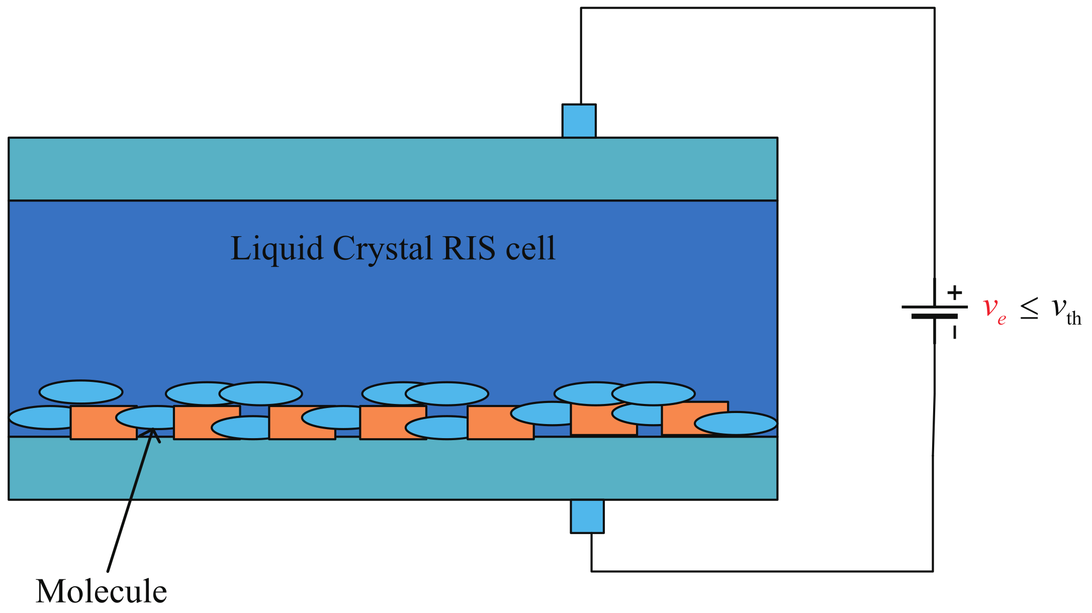
From the derivation mentioned above, we can know that the overall transition coefficient for the i-th incident light is correlated with the refractive index of LC RIS and the angle of the incidence for the incident light from the i-th LED. The angle of the incidence is usually related to the location of the receiver in the VLC after fixing the locations of the transmitters. In addition, the LC RIS can change the refractive index dynamically according to the environmental changes by applying an external voltage v e , as shown in Figure 2. The applied voltage can change the tilt angle specifying the molecular orientations of the LC RIS and, accordingly, influence the refractive index. Figure 3 and Figure 4 indicate the molecular orientations of the LC RIS cell before and after the external voltage is applied, respectively. Specifically, the tilt angle can be characterized by
ϵ = π 2 2 arctan [ exp ( v e v t h v 0 ) ] , v e > v t h , 0 , v e v t h ,
where v t h denotes the threshold voltage that allows the tilt process of the molecule to begin, v 0 denotes a constant, and ϵ represents the tilt angle. Meanwhile, the relationship between the tilt angle ϵ and the refractive index of LC RIS η c is given by [29].
1 η c 2 ( ϵ ) = cos 2 ϵ η up 2 + sin 2 ϵ η low 2 ,
where η up and η low are the upper and lower limit of the tunable refractive index for the LC RIS.

2.2. Amplification Coefficient

The light traveling through the LC RIS can be amplified with the application of external voltage [25], as shown in Figure 2. From the figure, we observe that the light intensity from the LC RIS, labeled as L 3 , was greater than the incident light intensity entering the LC RIS, labeled as L 1 . The amplification gain for the i-th channel can be expressed as [25]
β i = α i × exp ( Y i d ) ,
where d is the depth of the LC cell, and Y i is the negative absorption coefficient of the i-th channel for the LC RIS expressed as
Y i = 2 π v e η c 3 λ d cos ϕ i γ ,
where the wavelength of the incident light is denoted by λ , and the electro-optical conversion coefficient is represented by γ .
Consequently, the overall transmission gain can be characterized by
h i = g i × β i = G i × α i × exp ( Y i d ) , 1 i N .
Consequently, we see that the dynamic change in the refractive index can influence the overall transmission channel and enhance the communication performance from the derivation above.

3. Asymptotic Capacity Optimization

The asymptotic capacity with peak-constrained inputs for the LC RIS-aided MISO-VLC system is formulated in this section. Meanwhile, the tunable refractive index of the LC RIS is considered as an independent variable to optimize the asymptotic capacity. This section formulates the optimization problem, and accordingly, a metaheuristic algorithm is proposed to confirm the optimal refractive index.

3.1. Asymptotic Capacity Maximization Problem

The asymptotic capacity for the LC RIS-aided MISO-VLC system shaped like Figure 1 can be given by [30].
R η c = lim 𝒜 1 2 log ( ( i = 1 N h i ) 2 𝒜 2 2 π exp ( 1 ) σ 2 ) ,
where the peak-power constraint for the input signal is denoted by 𝒜 . From the derivation in (15), we see that the tunable refractive index of the LC RIS can only influence the overall transmission gain h i , and consequently, we can formulate the optimization problem as
max η c i = 1 N h i s . t . η low η c η up .
The problem is a highly nonconvex optimization problem, and consequently, it is difficult to solve the problem by adopting traditional algorithms. Hence, the particle swarm optimization (PSO) algorithm is proposed to solve the problem in our work. The PSO algorithm is a metaheuristic optimization algorithm leveraged to solve nonconvex problems. The principle of this algorithm is to simulate the foraging behavior of birds in a constrained search area [31]. In the following, a description of this algorithm’s specifics is provided.

3.2. Proposed Solution Algorithm

This paper adopts the PSO algorithm to deal with the optimization problems. For the practical problem proposed above, the location of each particle represents one possible value of the tunable refractive index. The searching space of the particle swarm is the set of all the possible values for the refractive index. The optimality of each particle is measured by the calculated value according to the objective function in (17). The location and velocity of one particle is updated iteratively to search for the optimal solution of the problem; meanwhile, the updating process should obey the laws characterized by
v i t + 1 = ω v i t + c 1 r 1 ( x i , p b e s t t x i t ) + c 2 r 2 ( x i , g b e s t t x i t ) ,
x i t + 1 = x i t + v i t + 1 ,
where the velocity of the i-th particle in the swarm, at the t-th iteration, is represented by v i t , and the best-recorded location of the i-th particle, until the t-th iteration evolution, is denoted by x i , p b e s t t , and x i , g b e s t t denotes the best-recorded location of the entire particle swarm until the t-th iteration evolution. Furthermore, ω is considered as the inertia weight, c 1 and c 2 are the acceleration constants (also known as “learning factors”), and r 1 and r 2 denote randomly selected constants subject to a uniform distribution in [ 0 , 1 ] . Meanwhile, the constraint on velocity needs to be imposed to prevent missing the ideal solution due to excessive velocity or a delay in achieving the final solution caused by the stagnant updating velocity for particles. Consequently, the velocity of the updating process meets v i t [ v max , v max ] , where v max is the maximum updating velocity set for each particle. All the vectors mentioned above have K elements, and K is the dimension of the independent variable for the optimization problems. According to (17), we see that the dimension of the vector is reduced to a one-dimensional variable (i.e., K = 1 ). Algorithm 1 indicates the pseudocode of the PSO algorithm.
Algorithm 1 The PSO Algorithm for Asymptotic Capacity Maximization
Input: 
Size of the particle swarm ; maximum iterations t max .
1:
Set: Constraints on velocity and location η low , η up , v max , v max ; objective function in (17); inertia weight ω ; acceleration constrants c 1 , c 2 .
2:
Initialization: Location of each particle x i = η c i [ η low , η up ] , 1 i ; velocity of each particle: v i [ v max , v max ] , 1 i ; the best-recorded location for the i-th particle: x i , p b e s t , 1 i ; the best-recorded location for the particle swarm: x i , g b e s t ; all the initial values are satisfied with the constraints mentioned above.
3:
 While  t t max
4:
  While  1 i
5:
   Refresh: The velocity and location of the i-th particle based on (18) and (19);
6:
   Calculate: The corresponding fitness according to the objective function in (17);
7:
   If the fitness of x i t + 1 is larger than the fitness of X i , p b e s t t
8:
     Choose:  x i t + 1 as the the i-th particle’s best-recorded location;
9:
    End If
10:
   If the fitness of x i , p b e s t t is larger than that of x g b e s t t
11:
    Choose:  x i , p b e s t t as the particle swarm’s best-recorded location;
12:
   End If
13:
  End While
14:
 End While
15:
return  η c * = x g b e s t t max and the corresponding optimal fitness of the particle swarm.
Output: 
The best location of the particle swarm η c * = x g b e s t t max ; the optimum value for the objection function.

3.3. Complexity Analysis

We consider the computational complexity of the proposed algorithm in this subsection. Firstly, the same number of operations is needed for the process of generating the initial particle and the initial velocity, characterized by 𝒪 ( K ) , where represents the size of the particle swarm, and K denotes the dimension of the independent variable. Hence, the process of initialization needs 𝒪 ( K ) + 𝒪 ( K ) = 𝒪 ( K ) operations. There are operations required to calculate the best-recorded location for each particle; meanwhile, the same number of operations is demanded to select the best-recorded location of the particle swarm. Secondly, the updating process for locations and velocities of the particle swarm needs 𝒪 ( K t max ) operations at most, where t max denotes the maximum iterations. It requires 𝒪 ( t max ) operations at most to calculate the historically optimal fitness of each particle; meanwhile, the same number of operations is needed to select the best-recorded position of the particle swarm according to the updated particles. Consequently, the computational complexity for the whole updating process in the worst-case scenario is 𝒪 ( K t max ) . Finally, the overall computational complexity of the proposed algorithm is 𝒪 ( K ) + 𝒪 ( K t max ) 𝒪 ( K t max ) .

4. Simulation Results and Analysis

Some simulations are detailed in this section to demonstrate the availability of the proposed algorithm in searching for the optimal value of the tunable refractive index for the LC RIS in MISO-VLC systems; meanwhile, we visualize the improvement provided by the LC RIS in the communication performance for the MISO-VLC systems.

4.1. Simulation Parameters

A 5 × 5 × 3 (m 3 ) room and 3 × 1 LC RIS-aided MISO-VLC system were considered in our simulations. We assumed the location of the PD was randomly chosen and satisfied with uniform distribution on the floor to guarantee the generality. Meanwhile, we chose the most probable locations in our daily life as the positions of the LEDs. The parameters in Algorithm 1 were set as = 10 and t max = 30 . The remaining values of the simulation parameters are summarized in Table 1.

4.2. Simulation Results

4.2.1. Convergence Analysis for the Proposed Algorithm

The convergence process of the proposed algorithm with different wavelengths of the transmission lights is displayed in Figure 5. The maximization of the asymptotic capacity for different wavelengths was achieved through the PSO algorithm with several iterations. By analyzing the results displayed in the figure, we see that the convergence rate of the proposed algorithm was fast enough to search for the optimal solution for the optimization problem proposed in the paper.

4.2.2. Asymptotic Capacity Performance Gain for the Optimal Design of LC RIS versus a Baseline Scheme

Figure 6 shows the asymptotic capacity performance gain for the optimal refractive index of LC RIS versus a randomly selected refractive index of LC RIS. The latter was considered as the baseline scheme for comparison. We chose the location of the PD randomly to guarantee generality. Meanwhile, the wavelength of the transmission light signal and the assignment scheme of the tuning refractive index for the LC RIS were changed to investigate the influence of the optimization algorithm and the wavelengths of the light signals on the communication performance for the LC RIS-aided MISO-VLC system. In this figure, “no-LC RIS” means that the receiver of the system was organized by an ordinary receiver containing a convex lens, “LC RIS-aided BSch” indicates that the LC RIS was tuned according to a baseline scheme, and the refractive index in this scheme was selected randomly from all the feasible values. “LC RIS-aided: PSO” represents that the refractive index was calculated by the proposed algorithm (the PSO algorithm). The difference among the wavelengths of transmission light signals is distinguished by different colors.
By comparing the “no-LC RIS” and “LC RIS-aided” curves from the figure, we see that the communication performance for the MISO-VLC systems was improved with the application of the LC RIS. Meanwhile, for the problems shaped as (17), the figure demonstrates that the PSO algorithm was an effective method. The proposed algorithm solved the nonconvex problem with several iterations, and the results provided by the PSO algorithm were much better than the BSch algorithm.

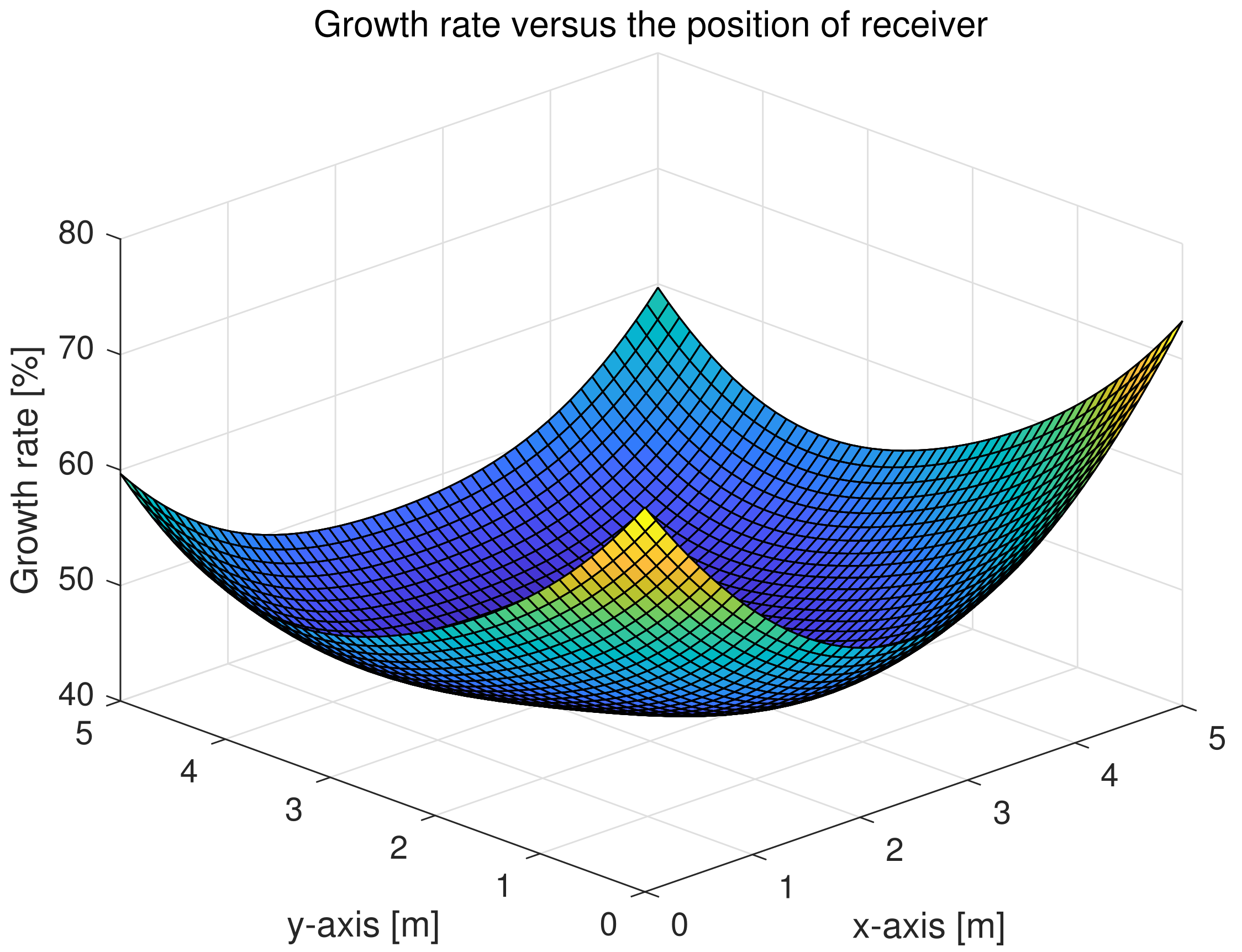
4.2.3. Growth Rate of the Performance versus the Position of the Receiver

Figure 7 shows the growth rate of the communication performance versus the position of the receiver after fixing the locations of the transmitters. We assumed that the wavelengths of the transmission lights were constant; meanwhile, the tunable refractive index of the LC RIS was calculated by the proposed algorithm according to the position of the receiver to confirm the optimal performance of the RIS. The growth rate in the corner of the room was higher than other locations, as shown the figure. This is a meaningful result, since the corner in indoor VLC systems is usually a dead zone (the area that the light cannot illuminate), and the quality of service in the corner is usually weak. Consequently, the application of the LC RIS improved the communication quality and solved the dead zone problems of the traditional VLC systems.

5. Conclusions and Future Research Directions

In this paper, an LC RIS-aided MISO-VLC system was first proposed, and an optimization problem with the tunable refractive index of LC RIS as the optimization variable was formulated accordingly. We considered the asymptotic capacity as the criterion characterizing the communication performance of the newly-established system model. As for the nonconvex optimization problem given in this paper, instead of adopting the exhaustive search method, the PSO algorithm was considered as the proper algorithm to solve the optimization problem. The simulation results demonstrated that the proposed algorithm was an effective approach to solve the proposed optimization problems, and the optimal refractive index of the LC RIS was found with several iterations. Meanwhile, compared with other assignment schemes for the LC RIS (random selection or no LC RIS), the refractive index calculated by the PSO algorithm helped the LC RIS-aided MISO-VLC system to maximize the communication performance improvement. Finally, we conducted simulations, which indicated that the application of the LC RIS improved the growth rate of the communication performance in the corner of the room moreso than other locations, which is an excellent result that contributes to solving the dead zone problems of traditional VLC systems.
The application of the RIS in VLC systems usually focuses on one type of RIS such as an LC RIS or a mirror-array-based RIS. However, the combination of different types of RIS may enable better performance improvement for traditional VLC systems. In the future, we would like to combine the mirror-array-based RIS deployed on walls and the LC RIS deployed in the receiver to achieve better communication performance for traditional VLC systems.

Author Contributions

Conceptualization, Q.W.; methodology, D.G.; software, Q.W.; validation, Q.W.; formal analysis, Q.W.; investigation, Q.W.; resources, Q.W.; data curation, G.X.; writing—original draft preparation, Q.W.; writing—review and editing, J.Z.; visualization, Q.W.; supervision, Y.Z.; project administration, J.Z.; funding acquisition, J.Z. All authors have read and agreed to the published version of the manuscript.

Funding

This research was supported by the National Natural Science Foundation of China (NSFC) under Grant (62071489) and the National Key Research and Development Project (2018YFB1801903).

Institutional Review Board Statement

Not applicable.

Informed Consent Statement

Not applicable.

Data Availability Statement

Not applicable.

Conflicts of Interest

The authors declare no conflict of interest.

References

  1. Samsung Research. 6G: The Next Hyper Connected Experience for All. 2020. Available online: https://research.samsung.com/next-generation-communications (accessed on 24 July 2022).
  2. Karunatilaka, D.; Zafar, F.; Kalavally, V.; Parthiban, R. LED based indoor visible light communications: State of the art. IEEE Commun. Surv. Tutorials 2015, 17, 1649–1678. [Google Scholar] [CrossRef]
  3. Luo, S.; Hao, J.; Ye, F.; Li, J.; Ruan, Y.; Cui, H.; Liu, W.; Chen, L. Evolution of the electromagnetic manipulation: From tunable to programmable and intelligent metasurfaces. Micromachines 2021, 12, 988. [Google Scholar] [CrossRef] [PubMed]
  4. ElMossallamy, M.A.; Zhang, H.; Song, L.; Seddik, K.G.; Han, Z.; Li, G.Y. Reconfigurable intelligent surfaces for wireless communications: Principles, challenges, and opportunities. IEEE Trans. Cogn. Commun. Netw. 2020, 6, 990–1002. [Google Scholar] [CrossRef]
  5. Basar, E.; Di Renzo, M.; De Rosny, J.; Debbah, M.; Alouini, M.S.; Zhang, R. Wireless communications through reconfigurable intelligent surfaces. IEEE Access 2019, 7, 116753–116773. [Google Scholar] [CrossRef]
  6. Guo, H.; Liang, Y.C.; Chen, J.; Larsson, E.G. Weighted sum-rate maximization for reconfigurable intelligent surface aided wireless networks. IEEE Trans. Wirel. Commun. 2020, 19, 3064–3076. [Google Scholar] [CrossRef] [Green Version]
  7. Ma, Q.; Bai, G.D.; Jing, H.B.; Yang, C.; Li, L.; Cui, T.J. Smart metasurface with self-adaptively reprogrammable functions. Light Sci. Appl. 2019, 8, 98. [Google Scholar] [CrossRef] [Green Version]
  8. Renzo, M.D.; Debbah, M.; Phan-Huy, D.T.; Zappone, A.; Alouini, M.S.; Yuen, C.; Sciancalepore, V.; Alexandropoulos, G.C.; Hoydis, J.; Gacanin, H.; et al. Smart radio environments empowered by reconfigurable AI meta-surfaces: An idea whose time has come. EURASIP J. Wirel. Commun. Netw. 2019, 2019, 129. [Google Scholar] [CrossRef] [Green Version]
  9. Feng, L.; Yang, H.; Hu, R.Q.; Wang, J. MmWave and VLC-based indoor channel models in 5G wireless networks. IEEE Wirel. Commun. 2018, 25, 70–77. [Google Scholar] [CrossRef]
  10. Aboagye, S.; Ngatched, T.M.; Dobre, O.A.; Ndjiongue, A.R. Intelligent reflecting surface-aided indoor visible light communication systems. IEEE Commun. Lett. 2021, 25, 3913–3917. [Google Scholar] [CrossRef]
  11. Wu, Q.; Zhang, J.; Guo, J.N. Position Design for Reconfigurable Intelligent-Surface-Aided Indoor Visible Light Communication Systems. Electronics 2022, 11, 3076. [Google Scholar] [CrossRef]
  12. Wu, Q.; Zhang, J.; Guo, J. Capacity Maximization for Reconfigurable Intelligent Surface-Aided MISO Visible Light Communications. Photonics 2022, 9, 487. [Google Scholar] [CrossRef]
  13. Qian, L.; Chi, X.; Zhao, L.; Chaaban, A. Secure visible light communications via intelligent reflecting surfaces. In Proceedings of the ICC 2021-IEEE International Conference on Communications, Montreal, QC, Canada, 14–23 June 2021; pp. 1–6. [Google Scholar]
  14. Sun, S.; Yang, F.; Song, J.; Han, Z. Joint resource management for intelligent reflecting surface–aided visible light communications. IEEE Trans. Wirel. Commun. 2022, 21, 6508–6522. [Google Scholar] [CrossRef]
  15. Sun, S.; Yang, F.; Song, J.; Zhang, R. Intelligent Reflecting Surface for MIMO VLC: Joint Design of Surface Configuration and Transceiver Signal Processing. arXiv 2022, arXiv:2206.14465. [Google Scholar] [CrossRef]
  16. Han, Y.; Xiao, Y.; Zhang, X.; Gao, Y.; Zhu, Q.; Dong, B. Design of dynamic active-passive beamforming for reconfigurable intelligent surfaces assisted hybrid VLC/RF communications. IET Commun. 2022, 16, 1531–1544. [Google Scholar] [CrossRef]
  17. Abdelhady, A.M.; Salem, A.K.S.; Amin, O.; Shihada, B.; Alouini, M.S. Visible light communications via intelligent reflecting surfaces: Metasurfaces vs. mirror arrays. IEEE Open J. Commun. Soc. 2020, 2, 1–20. [Google Scholar] [CrossRef]
  18. Aboagye, S.; Ndjiongue, A.R.; Ngatched, T.; Dobre, O.; Poor, H.V. RIS-Assisted Visible Light Communication Systems: A Tutorial. arXiv 2022, arXiv:2204.07198. [Google Scholar] [CrossRef]
  19. Ndjiongue, A.R.; Ngatched, T.M.; Dobre, O.A.; Haas, H. Re-configurable intelligent surface-based VLC receivers using tunable liquid-crystals: The concept. J. Light. Technol. 2021, 39, 3193–3200. [Google Scholar] [CrossRef]
  20. Ndjiongue, A.R.; Ngatched, T.M.; Dobre, O.A.; Haas, H. Toward the use of re-configurable intelligent surfaces in VLC systems: Beam steering. IEEE Wirel. Commun. 2021, 28, 156–162. [Google Scholar] [CrossRef]
  21. Forkel, G.J.; Krohn, A.; Hoeher, P.A. Optical interference suppression based on LCD-filtering. Appl. Sci. 2019, 9, 3134. [Google Scholar] [CrossRef] [Green Version]
  22. Krohn, A.; Forkel, G.J.; Hoeher, P.A.; Pachnicke, S. LCD-based optical filtering suitable for non-imaging channel decorrelation in VLC applications. J. Light. Technol. 2019, 37, 5892–5898. [Google Scholar] [CrossRef]
  23. Zhang, X.G.; Sun, Y.L.; Zhu, B.; Jiang, W.X.; Yu, Q.; Tian, H.W.; Qiu, C.W.; Zhang, Z.; Cui, T.J. A metasurface-based light-to-microwave transmitter for hybrid wireless communications. Light Sci. Appl. 2022, 11, 126. [Google Scholar] [CrossRef]
  24. Krohn, A.; Pachnicke, S.; Hoeher, P.A. Genetic optimization of liquid crystal matrix based interference suppression for VLC MIMO transmissions. IEEE Photonics J. 2021, 14, 1–5. [Google Scholar] [CrossRef]
  25. Aboagye, S.; Ndjiongue, A.R.; Ngatched, T.M.; Dobre, O.A. Design and Optimization of Liquid Crystal RIS-Based Visible Light Communication Receivers. IEEE Photonics J. 2022, 14, 1–7. [Google Scholar] [CrossRef]
  26. Lee, K.; Park, H.; Barry, J.R. Indoor channel characteristics for visible light communications. IEEE Commun. Lett. 2011, 15, 217–219. [Google Scholar] [CrossRef]
  27. Komine, T.; Nakagawa, M. Fundamental analysis for visible-light communication system using LED lights. IEEE Trans. Consum. Electron. 2004, 50, 100–107. [Google Scholar] [CrossRef]
  28. Hébert, M.; Hersch, R.D.; Emmel, P. Fundamentals of optics and radiometry for color reproduction. In Handbook of Digital Imaging; John Wiley & Sons: Hoboken, NJ, USA, 2015; pp. 1–57. [Google Scholar]
  29. Saleh, B.E.; Teich, M.C. Fundamentals of Photonics; John Wiley & Sons: Hoboken, NJ, USA, 2019. [Google Scholar]
  30. Moser, S.M.; Wang, L.; Wigger, M. Capacity results on multiple-input single-output wireless optical channels. IEEE Trans. Inf. Theory 2018, 64, 6954–6966. [Google Scholar] [CrossRef] [Green Version]
  31. Marini, F.; Walczak, B. Particle swarm optimization (PSO). A tutorial. Chemom. Intell. Lab. Syst. 2015, 149, 153–165. [Google Scholar] [CrossRef]
Figure 1. A MISO-VLC system with an LC RIS in the receiver.
Photonics 10 00128 g001
Figure 2. The detail of the propagation through the LC RIS.
Photonics 10 00128 g002
Figure 3. The molecular orientation of the LC RIS before applying the voltage.
Photonics 10 00128 g003
Figure 4. The molecular orientation of the LC RIS after applying the voltage.
Photonics 10 00128 g004
Figure 5. The convergence process of Algorithm 1 with different wavelengths of the light beams.
Photonics 10 00128 g005
Figure 6. Asymptotic capacity versus SNR with different schemes.
Photonics 10 00128 g006
Figure 7. Growth rate versus the position of receiver.
Photonics 10 00128 g007
Table 1. Simulation Parameters.
Name of ParameterValue
ψ 1 / 2 70
A PD 1 cm 2
a 1.5
Φ FoV 80
T o f ( ϕ i ) 1.0
γ 12 pm / V
η up 1.7
η low 1.5
η a 1.0
v 0 0.8 V
v t h 1.2 V
d 0.80 mm
σ 2 1 × 10 14
x max × y max × z max (m 3 ) 5 × 5 × 3   ( m 3 )
Disclaimer/Publisher’s Note: The statements, opinions and data contained in all publications are solely those of the individual author(s) and contributor(s) and not of MDPI and/or the editor(s). MDPI and/or the editor(s) disclaim responsibility for any injury to people or property resulting from any ideas, methods, instructions or products referred to in the content.