1. Introduction
Fiber lasers have been widely used in the fields of national defense, military, industrial processing and biomedicine due to their advantages of good beam quality, high conversion efficiency and compact structure [
1,
2,
3]. In particular, in the field of industrial processing, fiber laser is often used as a heat source for welding, coating, cleaning, cutting and so on [
4,
5,
6]. In recent years, with the increasing requirements for the quality of welding, cutting and other processes in industrial applications, researchers gradually found that the adjustable ring-mode laser has obvious advantages over the traditional circular laser. For example, when the laser is used for metal welding, the circular laser produces metal spatter, which will not only affect the welding quality, but can also easily pollute the welded joint. However, the adjustable ring-mode laser can greatly reduce the metal spatter generated by welding, and achieve higher quality welding [
7,
8,
9].
The adjustable ring-mode laser beam consists of two parts: a central circular beam and an outer annular beam. The power ratio between the central beam and the outer annular beam can be adjusted arbitrarily. In 2018, based on aluminum welding, M. R. Maina verified that the central beam of an adjustable ring-mode fiber laser is helpful to achieve adequate penetration depth, while the annular beam can ensure good temperature distribution [
9]. In 2020, based on steel welding, Mohammadpour M analyzed the welding performance of the adjustable ring-mode fiber laser and single beam fiber laser [
10]. It is concluded that under the same total power, the adjustable ring-mode fiber laser with a higher output power of central beam than annular beam has a greater penetration depth than the single beam fiber laser, and the adjustable ring-mode laser with a higher output power of annular beam than central beam can significantly reduce the spatter during welding [
10]. The mode of its output beam can be arbitrarily adjusted during the practical industrial applications of the adjustable ring-mode fiber laser. It can choose to output only the circular beam, only the annular beam or the composite beam. Besides, any power ratio of the central beam and the annular beam of a composite beam can be chosen arbitrarily according to different processing requirements, so as to achieve high-quality laser processing.
At present, there are a variety of technical means to output adjustable ring-mode fiber laser, such as using an optical lens to shape the laser beam, so that it is integrated into an adjustable ring-mode laser beam, or using fiber-combining technology to couple several laser beams into the central core and outer annular core of dual-core fiber. Compared with the optical lens method, the fiber-combining technology has the advantages of compact structure, flexible use and good stability [
11,
12].
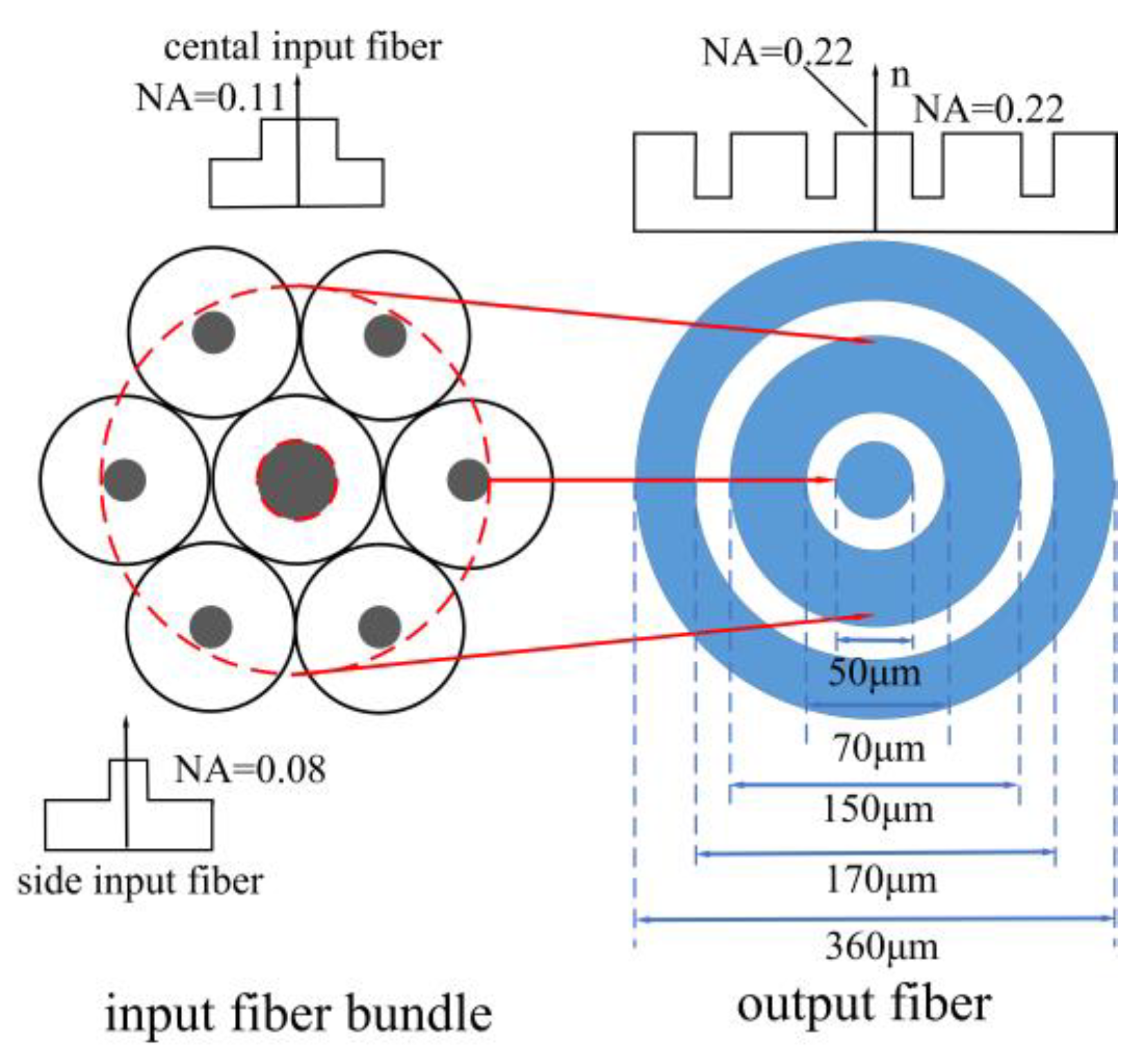
An adjustable ring-mode fiber signal combiner is a key component of outputting adjustable ring-mode fiber lasers by fiber-combining technology. This kind of combiner generally adopts a dual-core fiber containing a central circular core and an annular core as the output fiber, whose central and annular cores output the circular laser beam and annular laser beam, respectively, and the power of the circular beam and annular beam can be controlled separately by their respective incident laser sources. At present, the development of an adjustable ring-mode fiber signal combiner with high power and high beam quality has important application significance for fiber laser processing, which can expand the laser processing field and improve processing quality.
In this paper, a (6 + 1) × 1 adjustable ring-mode fiber signal combiner is prepared based on the tubing method. In order to maintain the beam quality of the central output beam, the fiber cladding corrosion technology is adopted for the central input fiber during the preparation process. In order to improve the output power of the central port, the fibers of 50 μm large core are selected as input and output fiber of the (6 + 1) × 1 combiner, so that the 3 × 1 fiber signal combiner can be cascaded to the central port of the (6 + 1) × 1 combiner. The test results show that the beam quality of the central port of the (6 + 1) × 1 combiner is degraded by only 8.3% and the central port is capable of carrying power on a level of 10 kW. The adjustable ring-mode fiber signal combiner developed in this paper can achieve a high power and high beam quality adjustable ring-mode fiber laser, which provides an important device support for the industrial application of a fiber laser.
3. Fabrication, Test, and Discussion
3.1. Fabrication of (6 + 1) × 1 Fiber Signal Combiner
According to the above simulation conclusion, the core of the central input fiber should not be tapered during the preparation of the combiner in order to maintain the beam quality of the central port. To achieve this goal, the following scheme is adopted: First, six side input fibers are tapered together as an annular shape to get a hollow fiber bundle, and then the corroded central input fiber is inserted into the hole of hollow taper-fused bundle; then, the combined fiber bundle which consists of central input fiber and six side fibers only needs to be fused at high temperatures instead of being tapered, in order to ensure that the mode field of the central input fiber core and the output fiber core match.
The specific manufacturing operation of (6 + 1) × 1 combiner based on the tubing method and fiber cladding corrosion technology has the following four steps.
The tapering of side input fibers. The outer diameter of the glass tube with the inner/outer diameters of 500/700 μm is tapered to about 525 μm, so that six side fibers of 25/125 μm are inserted into the tapered tube in an annular shape to form a hollow fiber bundle. Since the diameter of the ring formed by the core of six tapered side fibers should be in the range of 70–150 μm, the value range of a single tapered side fiber is 39–68 μm by calculation. To minimize the difficulty of operation, the maximum value of 68 μm is selected. Therefore, the waist diameter of fiber bundle composed by the six side fibers and glass tube should be tapered to 286 μm by calculation. The cross-section diagram of the waist region is shown in
Figure 3, and the diameter of the central hole of the fiber bundle is equal to the diameter of the single tapered side input fiber.
- 2.
The corroding of central input fiber. The cladding diameter of the central input fiber should be reduced to slightly less than the diameter of the central hole of the fiber bundle for the convenience of the subsequent bundling and cleaving process. At present, the hydrofluoric acid (HF) corrosion method is often used to reduce the diameter of fiber cladding, as HF will not cause damage to the fiber core when corroding the cladding. According to the corrosion rate of HF on the fiber cladding by repeated tests, the corroded central input fiber with smooth surface is obtained.
- 3.
The bundling and the fusing. The corroded central input fiber is inserted into the hollow taper-fused bundle, and then the bundle is just fused at high temperature instead of being tapered.
- 4.
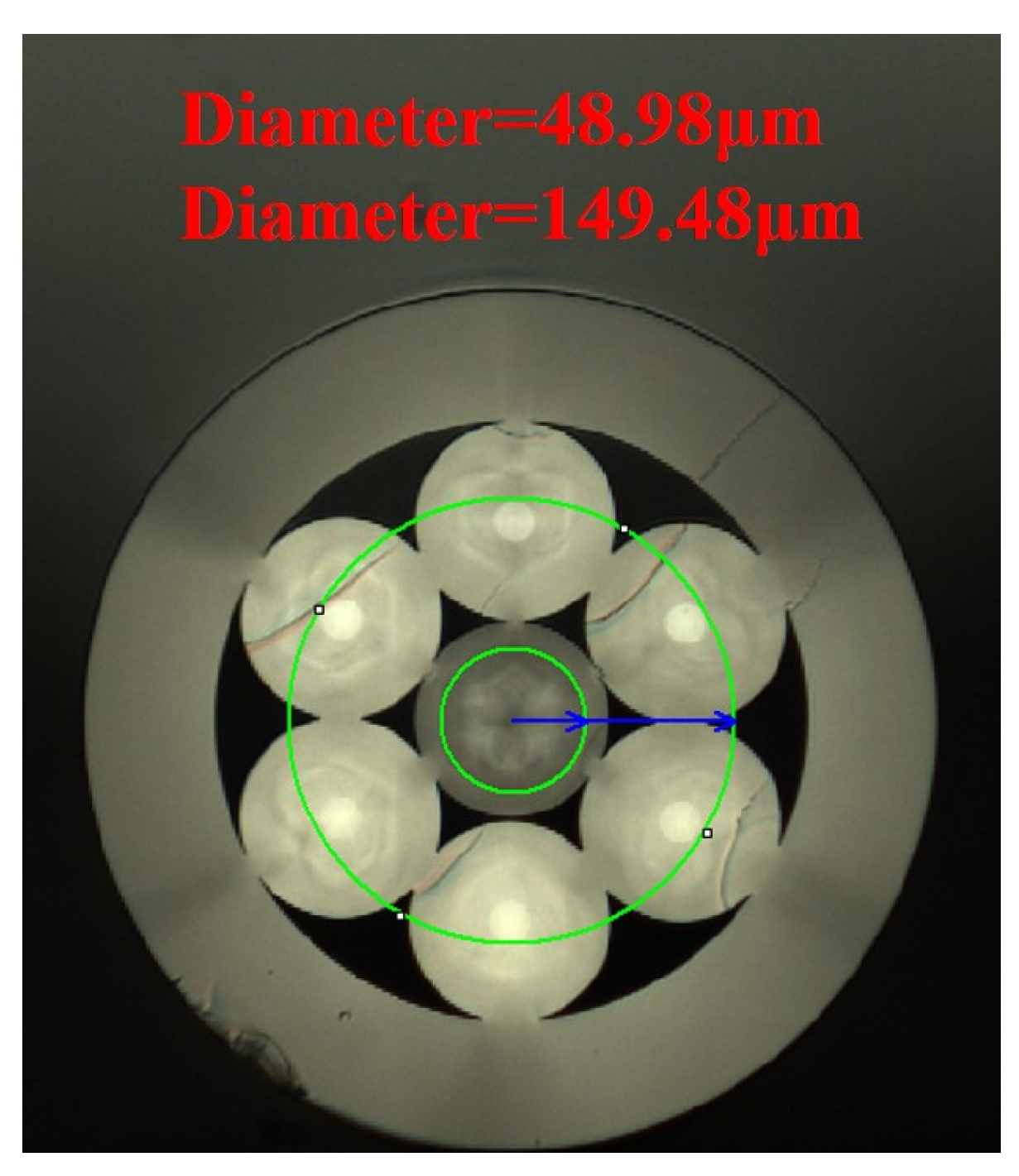
The cleaving and splicing. The waist region of the taper-fused bundle is cleaved by a large core fiber cleaving system to ensure the smooth cleaving cross-section. The cross-section image observed under the microscope is shown in
Figure 4. The core diameter of the central input fiber is 49 μm, and there is basically no deformation, which can ensure the beam quality of the central port. The cladding surface of the output fiber is roughened by the scrub containing HF in order to make the cladding light not meet the total reflection condition, and thus the cladding light is stripped out. After the cleaving process, the fiber bundle is spliced with the output fiber by using the fiber fusion splicer, which uses a CO
2 laser as the heat source. After the above steps, the combiner is completed.
3.2. Measurement of Single-Port Transmission Efficiency and Beam Quality
After fabrication, an ytterbium-doped fiber laser (YDFL) with a central wavelength of 1080 nm and pigtail of 25/400 μm fiber is used to test the performance of the (6 + 1) × 1 combiner. Firstly, the beam quality of the laser itself and the output laser transmitted through a single 50/250 μm fiber is tested. When the pigtail of the YDFL is directly fused with an end cap whose pigtail fiber is 50/70/150/170/360 μm, the measured beam quality is M
2 = 2.24. The test diagram and beam quality are shown in
Figure 5a,b, respectively. When the laser is transmitted into the end cap through a single 50/250 μm fiber, the measured beam quality is M
2 = 3.15. The test diagram and beam quality are shown in
Figure 5c,d, respectively.
When the laser is transmitted into the end cap through the central port and side port of (6 + 1) × 1 combiner, respectively, as shown in
Figure 6a,b, the beam quality and output power of the central and side port are tested. The beam quality of the central port and side port is measured as M
2 = 3.41 and M
2 = 16.84 and the output spots are shown in
Figure 6c and
Figure 6d, respectively. When the input power of single port is 1834 W, the output power of the central port and the side port reaches 1824 W and 1820 W, and the transmission efficiency reaches 99.5% and 99.2%, respectively. In both cases, the temperature of the combiner does not rise significantly. The test results show that under the same injection condition, the beam quality transmitted through the central port of the (6 + 1) × 1 combiner is degraded by only 8.3% compared with that transmitted through a single 50/250 μm fiber. This shows that the scheme of reducing the mode field mismatch between the input fiber core and the output fiber core by fiber corrosion technology is feasible to maintain the beam quality of the (6 + 1) × 1 combiner.
Two YDFLs are injected into the central and side port of the (6 + 1) × 1 combiner at the same time (as shown in
Figure 7), and the measured spot is inserted in
Figure 7. It can be seen that the annular beam and the circular beam are independent of each other.
It can be seen from the above experimental results that the output beam mode of the (6 + 1) × 1 combiner can be adjusted by controlling the incident laser sources of the central port and the side port. When only the laser is injected into the central port, the circular beam is output (as shown in
Figure 6c). When only lasers are injected into the side ports, the annular beam is output (as shown in
Figure 6d). When lasers are injected into the center and side ports simultaneously, the composite beam is output (as shown in
Figure 7). In addition, different power ratios of circular beam and annular beam can be achieved by controlling the power of the incident laser source in the central and side ports, respectively.
3.3. Cascade Experiment and Results
In order to improve the output power of central beam of the adjustable ring-mode laser, the scheme of cascading a 3 × 1 fiber signal combiner to the central port of the (6 + 1) × 1 combiner is adopted. The 3 × 1 fiber signal combiner uses 25/250 μm (NA = 0.065) input fiber and 50/250 μm (NA = 0.11) output fiber. The home-made 3 × 1 fiber signal combiner is fabricated by the tubing method, and the output fiber is roughened to strip out the cladding light [
13,
14]. A YDFL is used to carry out the single-arm test on the three ports (f1–f3) of 3 × 1 combiner successively, as shown in
Figure 8a. The beam quality test results are shown in line 2 of
Table 1 as M
2 = 4.90, M
2 = 4.20, M
2 = 4.48, respectively, and the light spots are shown in
Figure 8b–d. When the input power is 1834 W, the output power of the three ports is 1764 W, 1777 W and 1763 W, and the transmission efficiency is 96.2%, 96.9% and 96.1%, respectively.
As shown in
Figure 9a, the output light of YDFL is transmitted into the central port of the (6 + 1) × 1 combiner through the 3 × 1 combiner, and then transmitted into the 50/70/150/170/360 μm end cap through the output fiber of the (6 + 1) × 1 combiner. The cascade test is conducted on the three ports (f1–f3) of the 3×1 combiner successively. The beam quality results are shown in line 3 of
Table 1 as M
2 = 5.52, M
2 = 4.45, M
2 = 5.24, respectively, and the light spots are shown in
Figure 9b–d. When the input power is 1834 W, the output power of the three ports is 1745 W, 1760 W and 1748 W, and the overall transmission efficiency is 95.1%, 96.0% and 95.3%, respectively. It can be seen from the test results that the overall transmission efficiency of the (6 + 1) × 1 combiner can reach more than 95% after the cascading of the 3×1 combiner in the central port, and there is a low degree of beam quality deterioration.
3.4. Discussion
According to the efficiency and temperature rise of the single-arm and cascade tests, it can be concluded that the power-bearing capacity of the (6 + 1) × 1 combiner has great potential. Considering that the current maximum output power of YDFL with a core of 25 μm is 3–4 kW, and that there is no obvious temperature rise when the central and side ports of the (6 + 1) × 1 combiner are injected into power of 1.8 kW respectively, it can be reasonably predicted that the maximum power of the central port of the (6 + 1) × 1 combiner can reach a level of 10 kW, and the maximum power of the side ports can reach a level of 20 kW. In addition, the combiner keeps a low degree of beam quality degradation during the single test and the cascade test because the mode field mismatch of the combiner is reduced by the fiber corrosion technology. The high maintenance of beam quality and the high transmission efficiency of the cascade test provide feasibility for the output of a higher-power and higher-beam-quality adjustable ring-mode fiber laser.
4. Conclusions
In this paper, a (6 + 1) × 1 adjustable ring-mode combiner is prepared by fiber cladding corrosion technology. The test result shows that under the same injection condition, the beam quality transmitted through the central port of the combiner is degraded by only 8.3% compared with that transmitted through a single 50/250 μm fiber. It verifies that the fiber cladding corrosion technology is feasible to maintain the beam quality of the central port of the combiner.
In order to improve the output power of the central port of the adjustable ring-mode combiner, the scheme of cascading a 3 × 1 fiber signal combiner in the large core central port of the (6 + 1) × 1 combiner is adopted. It can be predicted that the maximum power of the central port and the side ports of the (6 + 1) × 1 combiner can reach a level of 10 kW and 20 kW, respectively. If the fabrication process of the combiner is further optimized, both the circular beam and the annular beam of the combiner can achieve high beam quality and high power-bearing capacity, and the practical value of the combiner in industrial processing applications can be ensured to a greater extent.


