Article

Experimental Synthesis and Demonstration of the Twisted Laguerre–Gaussian Schell-Mode Beam

1
School of Physical Science and Technology & Collaborative Innovation Center of Suzhou Nano Science and Technology, Soochow University, Suzhou 215006, China
2
Shandong Provincial Engineering and Technical Center of Light Manipulations & Shandong Provincial Key Laboratory of Optics and Photonic Devices, School of Physics and Electronics, Shandong Normal University, Jinan 250014, China
*
Authors to whom correspondence should be addressed.
Photonics 2023, 10(3), 314; https://doi.org/10.3390/photonics10030314
Submission received: 13 February 2023 / Revised: 10 March 2023 / Accepted: 12 March 2023 / Published: 14 March 2023
(This article belongs to the Special Issue Advances and Application of Optical Manipulation)

Abstract

:
The twisted Laguerre–Gaussian Schell-model (TLGSM) beam is a novel type of partially coherent beam embedded with both the second-order twist phase and the classical vortex phase. The intriguing properties induced by the interaction of the two types of phases have been demonstrated theoretically quite recently. In this work, we introduce a flexible way to experimentally synthesize a TLGSM beam with controllable twist strength. The protocol relies on the discrete pseudo-mode representation for the cross-spectral density of a TLGSM beam, in which the beam is viewed as an incoherent superposition of a finite number of spatially coherent modes. We show that all these pseudo modes endowed with random phases are mutually uncorrelated and can be encoded into a single frame of a dynamic computer-generated hologram. By sequentially displaying dynamic holograms on a single spatial-light modulator, the controllable TLGSM beam can be synthesized experimentally. The joint effect of the two phases on the propagation and self-reconstruction characteristics of the synthesized beam has also been studied in the experiment.

1. Introduction

Spatial optical coherence, which is characterized by the spatial degree of coherence (DOC) function between two spatial points of a light field, can be regarded as an efficient degree of freedom to manipulate the statistical properties of light fields during propagation and light–matter interactions [1,2,3]. In recent years, the non-trivial phase of the spatial DOC function of partially coherent sources has received considerable attention [4,5,6,7,8,9,10,11]. By elaborately tailoring the phase of spatial coherence, partially coherent beams can exhibit distinguished propagation properties (compared to the classical Gaussian Schell-model beams), such as self-acceleration, self-focusing, self-steering, and self-reconstruction properties, which have promising applications in super-resolution imaging, optical encryption, micromanipulation, and image transmission [12,13,14,15,16,17,18].
Among all various forms of phases partially coherent beams have been endowed with, the vortex phase [19] and the twist phase [20,21,22,23,24] have attracted continual attention due to their peculiar properties and applications. A beam carrying the vortex phase is associated with the orbital angular momentum (OAM) state denoted as exp ( i l φ ) , where l is the topological charge and φ is the angular coordinate [25]. As OAM states with different topological charges are mutually orthogonal, they can form infinite dimensions in the Hilbert space [26]. Thus, the vortex phase can be used as an additional degree of freedom to improve the information capacity of optical communication systems [27,28]. In recent years, its application has been extended to microscopy [29,30], optical trapping [31], detection of spinning objects [32], defect detection in conventional nano-structures [33], and artificial spin ice systems [34]. The twist phase differs completely from the conventional phases carried by a fully coherent beam. It is a quartic inseparable phase that depends on two spatial points and can only survive for a partially coherent beam [20]. Recently, it has been demonstrated that a partially coherent beam embedded with a twist phase leads to a new kind of classical entanglement that can be applied to quantum information processing through the turbulent atmosphere [35,36]. Such a second-order twist phase also endows partially coherent beams with the OAM, which is responsible for the beam spot rotation during propagation [37,38]. The effect of these two different phases has been studied separately in the field of partially coherent beams. In 2018, we first introduced a partially coherent beam named the twisted Laguerre–Gaussian Schell-model (TLGSM) beam, which carries both the twist phase and the vortex phase [39]. It has been found that the combination of the two phases can bring about the nonlinear coupling term for the OAM density, which can greatly increase the amount of OAM for the beam. In addition, we found theoretically that the handedness of the vortex phase and the twist phase affects the propagation and self-reconstruction characteristics of the beam [40]. It is remarkable that the opposite handedness between two phases can enhance the side rings of the spatial distribution for the spatial DOC in the far field, which provides an efficient way to determine the topological charges of the vortex phase carried by the partially coherent beam.
Here, we focus on the experimental generation of a TLGSM beam and demonstration of the combination effect of two phases. It was a challenging task to experimentally implement a partially coherent source endowed with a twist phase since the first introduction of this phase model. To the best of our knowledge, over the past 30 years, only Friberg and coauthors have reported the transformation of an anisotropic Gaussian Schell-model beam into the twisted Gaussian Schell-model (TGSM) beam (with topological charge l = 0 ) by using a six-cylindrical-lens optical system [41]. Recently, we simplified the protocol with only a three-cylindrical-lens system [42]. However, due to the restricted condition between the focal distances of the cylindrical lenses and the twist factor of the twist phase, such an approach cannot adapt to the situations in which the beam parameters, such as the twist factor and the spatial coherence width, are required to be adjustable. To solve the problem, methods based on the coherent-mode representation [43], pseudo-mode representation [44], and random-mode representation [45] have been proposed. The core of these methods is that a partially coherent twisted beam can be decomposed into a finite number of uncorrelated optical modes. Different series of optical modes are obtained from the three different representations for the cross-spectral density function of the beam.
In this work, we use the pseudo-mode representation method to synthesize a TLGSM beam. The advantage of the pseudo-mode representation method is that the optical modes can be obtained conveniently by discretizing Gori’s non-negative definiteness criterion compared to the coherent-mode representation and the convergence speed of the modes is faster than that of the random-mode representation [46]. We show that all the required pseudo modes can be encoded into a single frame of a dynamic computer-generated hologram by adding the Gaussian random phases into the modes. A TLGSM beam can be successfully generated by sequentially displaying the dynamic holograms on a single spatial-light modulator. In addition, the beam parameters can be controlled easily in the experiment by altering the dynamic holograms. The combination effect of the twist phase and the vortex phase on the evolution properties of a partially coherent beam is also demonstrated in our work.
This work is organized as follows. In Section 2, we introduce the pseudo-mode representation for a TLGSM beam and numerically study the propagation and self-reconstruction properties of the TLGSM beam with this representation. In Section 3, we show the experimental details for synthesizing a TLGSM beam with controllable beam parameters. The experimental results are also presented in this section. In Section 4, we summarize this work.

2. Theory

2.1. Pseudo-Mode Representation for a TLGSM Beam

In the space–frequency domain, the second-order statistical properties of partially coherent sources can be described in terms of their cross-spectral density (CSD) functions at a pair of points in space [1]. The CSD function for a TLGSM beam in the source plane ( z = 0 ) is expressed as [39]
W ( r 1 , r 2 ) = ( r 1 r 2 ) | l | exp [ i l ( φ 1 φ 2 ) ] exp ( r 1 2 + r 2 2 4 σ 0 2 ) exp [ ( r 1 r 2 ) 2 2 δ 0 2 ] , × exp [ i k μ ( x 1 y 2 x 2 y 1 ) ]
where the angular frequency ω is omitted for simplicity, r 1 = ( x 1 ,   y 1 ) and r 2 = ( x 2 ,   y 2 ) are two arbitrary transverse position vectors in the source plane, and σ 0 and δ 0 denote the beam width and transverse coherence width, respectively. The phase term exp [ i l ( φ 2 φ 1 ) ] represents the vortex phase, with the azimuthal angle φ = arctan ( y / x ) and l being the topological charge. The last phase term, exp [ i k μ ( x 1 y 2 x 2 y 1 ) ] , denotes the twist phase, with k = 2 π / λ being the wave number and μ being the twist factor representing the strength of the twist phase. The parameter μ has a real value and dimension of the inverse of length. It should be noted that the magnitude of μ is determined by the inequality | μ | ( k δ 0 2 ) 1 to satisfy the non-negative definiteness of the CSD function [20].
Based on Gori’s non-negative definiteness criterion, the CSD function can be elegantly expressed in a continuous integral form, i.e., [47]
W ( r 1 , r 2 ) = p ( v ) H * ( r 1 , v ) H ( r 2 , v ) d 2 v ,
where p ( v ) is a non-negative weight function, H ( r ,   v ) is an arbitrary kernel, and the asterisk denotes the complex conjugate. For a TLGSM source, p ( v ) and H ( r ,   v ) take the forms
p ( v ) = exp [ 2 a σ 0 2 ( v x 2 + v y 2 ) 4 a + σ 0 2 ] ,
H ( r , ν ) = 2 a π r | l | exp [ 4 σ 0 2 1 + 4 a σ 0 2 ( r 4 σ 0 2 + a r a v ) 2 + i k μ ( x v y y v x ) ] exp ( i l φ ) ,
where a is a positive parameter determined by δ 0 and μ , i.e.,
δ 0 2 = a + ( k μ ) 2 4 a .
The continuous integral in Equation (2) can be represented by a discrete form through a two-dimensional comb function sampling, i.e.,
W ( r 1 , r 2 ) = m M n N p ( v m n ) H * ( r 1 , v m n ) H ( r 2 , v m n ) ,
where v m n = ( v m , v n ) are two-dimensional discrete variables, H ( r , v m n ) are the pseudo modes, and p ( v m n ) are the corresponding non-negative weights. Similar to the well-known coherent-mode representation, the CSD can be regarded as the incoherent superposition of suitable weighted mutually uncorrelated pseudo modes. Considering the difficult task to exploit the eigenfunctions and the associated eigenvalues in the coherent-mode representation [1], it is obvious that the pseudo-mode representation method is more convenient and flexible. Equation (6) implies that an infinite number of modes is required to represent the CSD function of a TLGSM source. Nevertheless, the non-negative function p ( v m n ) converges quickly toward zero as the mode indices m and n increase. Therefore, an appropriate number of discrete modes is necessary to achieve concise approximation in a practical situation.
Next, we take the TLGSM source with specific parameters l = 2 , δ 0 = 0.66 mm, σ 0 = 0.3 mm, and μ = ± 1.5 × 10 4   mm 1 as an example. We simulate with different numbers of pseudo modes to find the suitable indices for M and N . During the sampling process, v m n is equally spaced in a confidence interval [ 2 2 ( 4 σ 0 2 + 1 / a ) , 2 2 ( 4 σ 0 2 + 1 / a ) ] , where ( 4 σ 0 2 + 1 / a ) / 2 is the waist width of the weighting function, as shown in Equation (3). Figure 1 shows the variation of p ( v m n ) with indices m and n when the total number of the discrete modes is selected as M = N = 5 , M = N = 7 , and M = N = 15 . The spatial distribution of p ( v ) in Equation (3) is displayed in Figure 1a as a reference. It is found that with the increase in the mode indices, the value of p ( v m n ) decreases, implying that pseudo modes with higher modal indices have less contribution. In addition, with the increase in the total mode number M × N (or the decrease in the separations between v m n ), the spatial distribution for p ( v m n ) becomes closer to the spatial distribution of the continuous function p ( v ) .
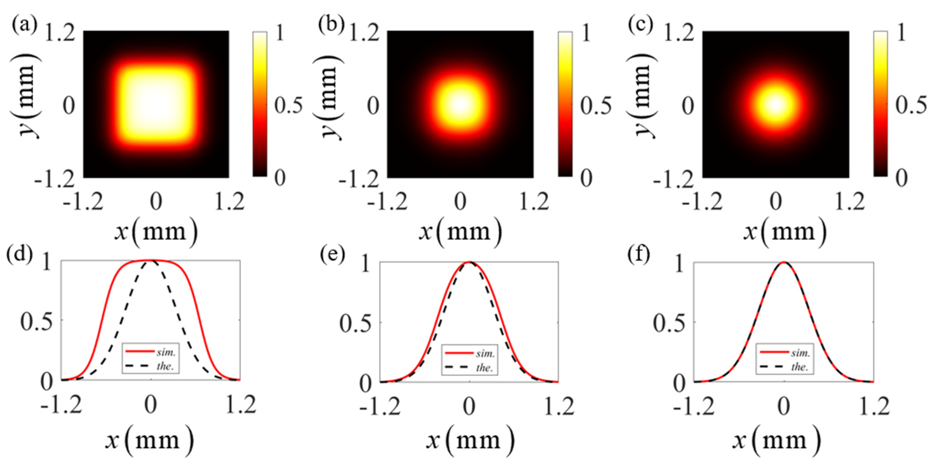
To see whether the discrete pseudo-mode representation could constitute a TLGSM beam, we next examine the spectral density and spatial degree of coherence (DOC) of the beam synthesized with M × N pseudo modes. Both the spectral density and the spatial DOC can be obtained with the help of Equation (6), i.e., the spectral density S ( r ) = W ( r , r ) and the spatial DOC γ ( r 1 , r 2 ) = W ( r 1 , r 2 ) / S ( r 1 ) S ( r 2 ) . In Figure 2, we show the spatial distributions for the spectral density of the synthesized beams, with the mode numbers being M × N = 5 × 5 , M × N = 7 × 7 , and M × N = 15 × 15 . We find that with the increase in the number of pseudo modes, the spectral density distribution of the synthesized beam becomes more consistent with that of a TLGSM beam expressed by Equation (1). When the number of the modes reaches 225 with M = N = 15 , it is found that the spectral density distribution of the synthesized beam matches perfectly with the theoretical model. In Figure 3, we show the spatial distribution for the DOC | γ ( r 1 , r 2 ) | , where r 1 = ( x , y ) and r 2 = ( x , y ) . It is obvious that as the number of modes increases, the spatial distribution for the degree of coherence of the synthesized beam gradually approximates that for a TLGSM beam. When the number of modes reaches 15 × 15 , the synthesized spatial DOC nearly coincides with the theoretical result obtained with Equation (1). These simulation results indicate that a satisfactory TLGSM source can be obtained by superimposing appropriate quantities of discrete pseudo modes. For the examples of the TLGSM beams studied in this work, we find 15 × 15 pseudo modes are sufficient.

2.2. Examining the Propagation Properties with Pseudo-Mode Representation

In this subsection, we use the aforementioned pseudo-mode representation to investigate the coexistent effect of the vortex phase and the twist phase on the statistical properties of a TLGSM beam during paraxial propagation. Within the accuracy of paraxial approximation, the propagation of each pseudo mode of a TLGSM beam passing through a stigmatic ABCD optical system can be treated with the following Collins integral [48]:
H ( ρ , v m n ) = i k 2 π B exp [ i k D ( ρ x 2 + ρ y 2 ) 2 B ] H ( r , v m n ) exp [ i k A 2 B ( x 2 + y 2 ) ] , × exp [ i k B ( x ρ x + y ρ y ) ] d x d y
where H ( ρ , v m n ) denotes the output pseudo mode, with ρ being the spatial position vector in the output plane; k is the wavenumber as before; and A , B , C , and D are the elements of the transfer matrix for the optical system. Taking all the output pseudo modes into account, we obtain the CSD of the TLGSM beam in the output plane represented by the following superposition form, i.e.,
W ( ρ 1 , ρ 2 ) = m = 1 M n = 1 N p ( v m n ) H ( ρ 1 , v m n ) H ( ρ 2 , v m n ) .
Substituting the analytical expression of the pseudo mode and its corresponding weight for a TLGSM source into Equations (7) and (8), we can conveniently simulate the propagation properties, including the spectral density and the spatial DOC of the TLGSM beam.
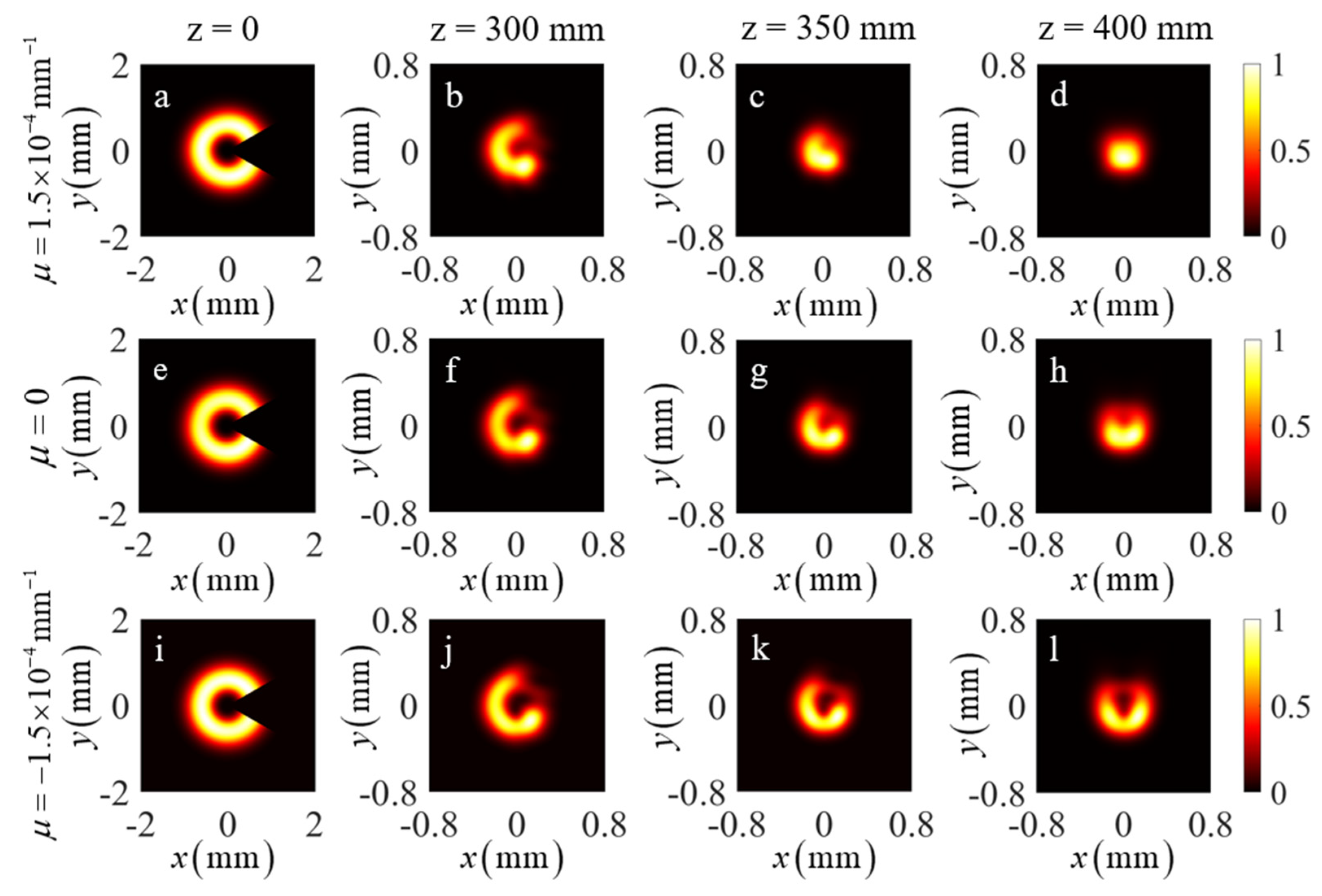
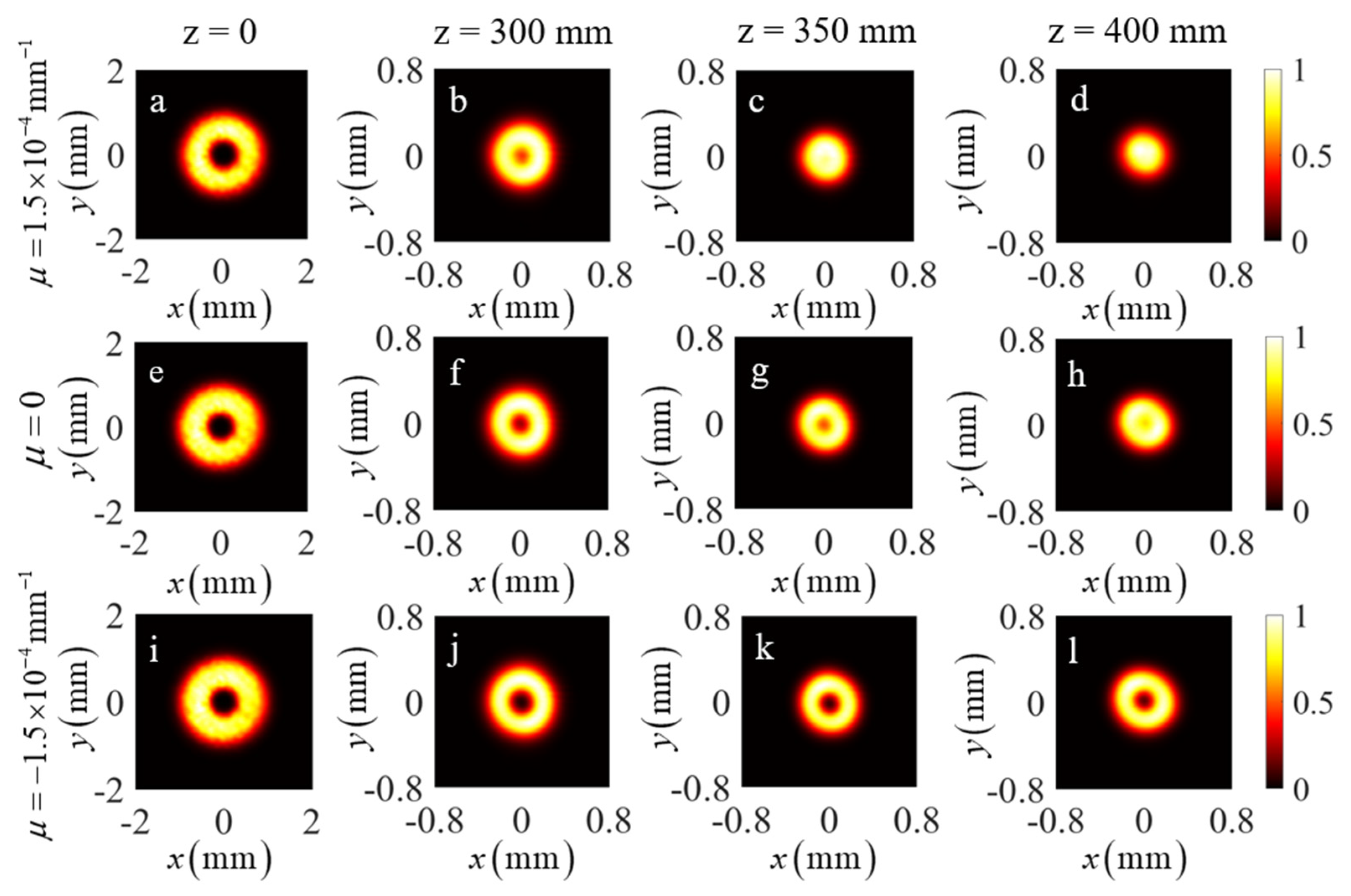
As a numerical example, a focusing system composed of a thin lens with focal distance f locates in the source plane of the beam and the simulated propagation properties of the beam at a distance z after the lens are examined. The elements of the transfer matrix for such an optical system are A = 1 z / f , B = z , C = 1   /   f , and D = 1 . Figure 4 illustrates the spatial distributions for the spectral density of the TLGSM beam at different propagation distances. The topological charge of the beam is l = 2 , and the twist factor μ of the twist phase is controlled to be μ = ± 1.5 × 10 4   mm 1 and μ = 0 . Other parameters for the beam and optical system are δ 0 = 0.66 mm, σ 0 = 0.3 mm, λ = 632.8   nm , and f = 400   mm . From the simulation results shown in Figure 4, one can see that the beam embedded with only the vortex phase gradually evolves from a donut shape into a quasi-Gaussian shape, as expected. This is due to the reduced spatial coherence in the beam source. When the twist phase is considered, we demonstrate in the top row and the bottom row of Figure 4 the influence caused by the handedness of the orbital angular momentum affiliated with the twist phase. The beam’s ability of preserving the donut shape diminishes as the twist factor μ takes a positive value, which indicates that the handedness of the orbital angular momentum affiliated with such a twist phase is opposite to that of the vortex phase with the positive topological charge. On the contrary, the ability of preserving the donut shape for the beam enhances when the twist factor μ takes a negative value, indicating the same handedness of the orbital angular momentum induced by the twist phase and the vortex phase.
Next, we simulate the effect of the twist phase on the self-reconstruction ability of the spectral density and spatial DOC of a TLGSM beam with the pseudo-mode representation. In the simulation, the TLGSM beam in the source plane is partially blocked by a sector-shaped opaque obstacle (SSOO) with the transmittance function O ( r ) . The pseudo mode of the TLGSM beam in the output plane of the ABCD optical system thus becomes
H ( ρ , v m n ) = i k 2 π B exp [ i k D ( ρ x 2 + ρ y 2 ) 2 B ] H ( r , v m n ) O ( r ) exp [ i k A 2 B ( x 2 + y 2 ) ] . × exp [ i k B ( x ρ x + y ρ y ) ] d x d y
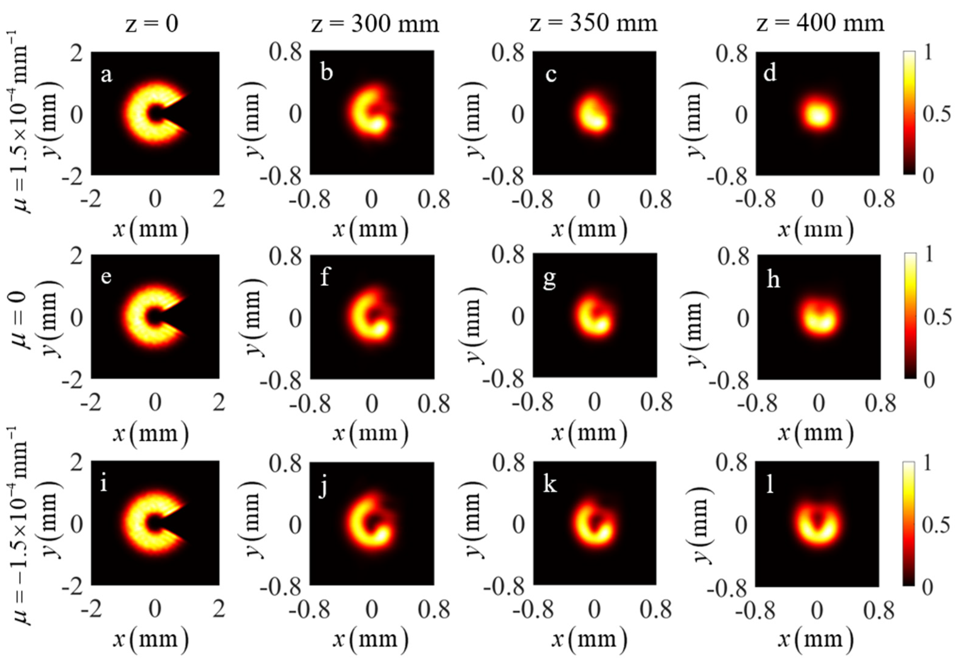
Substituting Equation (9) into Equation (8), the spectral density and spatial DOC of the obstructed TLGSM beam in the output plane can be obtained conveniently. In Figure 5, we display the spatial distributions for the spectral density of TLGSM beams with different twist factors μ at different propagation distances through a focusing system. The closing angle of the SSOO in the source plane is α = π / 3 (see in the left panel of Figure 5). From the simulation results, we find that the notch of the ring-shaped profile keeps rotating during propagation, since the beam carries the orbital angular momentum that is induced by the vortex phase and the twist phase. In addition, it is found that the notch in the spectral density faces just right up when the beam is in the focal plane, while it faces the right direction in the source plane, indicating a π / 2 rotation of the beam along the counterclockwise direction. The simulation results are consistent with the theoretical predictions in Ref. [39]. From the right panels of Figure 5, one can find that the notch in the spectral density gradually fades away in the focal plane as the twist factor varies from negative to positive. For μ = 1.5 × 10 4   mm 1 , the focal-plane beam profile is well reconstructed (see Figure 5d) in comparison to that when the SSOO is removed in the input plane (see Figure 4d).
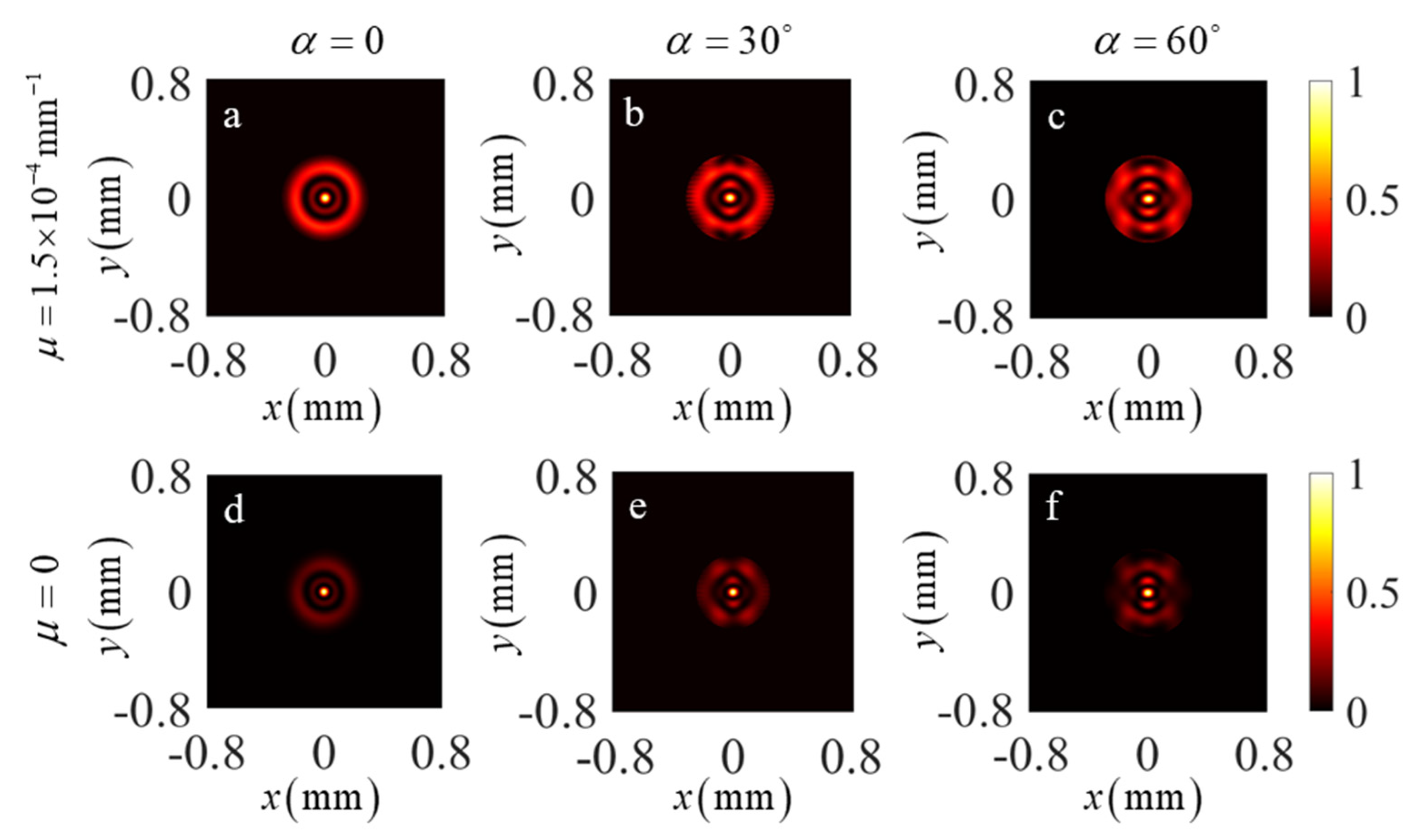
We then calculate the spatial DOC between the points ρ and ρ of the focused obstructed beam with a positive twist factor μ = 1.5 × 10 4   mm 1 in the focal plane, and we present in Figure 6 the spatial distribution of the DOC | γ ( ρ , ρ ) | 2 under different closing angles of the SSOO. For a better comparison, the corresponding DOC distributions of the obstructed beams with μ = 0 are also presented in Figure 6. It is clear the magnitude of the side rings in the spatial distribution of DOC is significantly enhanced (top panels of Figure 6) when the twist phase with a positive twist factor is present in the beam. The enhancement benefits from the quasi-Gaussian distribution of the spectral density for the TLGSM beam with μ = 1.5 × 10 4   mm 1 (see in Figure 4d and Figure 5d). In addition, we find the spatial distribution of the DOC for the TLGSM beam has the self-reconstruction capacity when the beam is partially blocked. As shown in the bottom panels of Figure 6, even when the beam carries no twist phase and the beam is blocked by an SSOO, the topological charge of the incident beam can still be identified by counting the dark-ring dislocations in the spatial distribution of the DOC in the focal plane. When the twist phase with μ = 1.5 × 10 4   mm 1 is present, we find that the self-reconstruction capacity of an obstructed TLGSM beam is enhanced since the magnitude of the bright side rings of the DOC is enhanced as well. Therefore, the number of dark-ring dislocations can be identified more easily despite the increase in the obstruction section, which makes the detection of the topological charge of a partially coherent vortex beam more reliable. We remark that these simulation results obtained with the pseudo-mode representation method are well consistent with those reported previously [33].

3. Experiment

In this section, we carry out an experiment to synthesize a TLGSM source and verify the beam’s propagation properties and its self-reconstruction capacity. Based on the pseudo-mode representation, experimentally synthesizing a TLGSM beam can be realized through incoherent superposition of the obtained pseudo modes with the corresponding non-negative weights. The pseudo modes are generated with the dynamic hologram located on the spatial-light modulator (SLM). However, to guarantee that the pseudo modes are statistically independent, additional random phases need to be imposed on each pseudo mode. Therefore, one frame of the dynamic complex holograms is determined by the following expression:
ϕ t ( r ) = m = 1 M n = 1 N p ( v m n ) H ( r , v m n ) exp [ i γ t ( v m n ) ] ( t = 1 , 2 , , T ) ,
where ϕ t ( r ) denotes the complex phase pattern of one frame loaded on the SLM, γ t ( v m n ) is the attached random phase on each pseudo mode and the spatial distribution of this phase is uniformly distributed in the interval [ 0 ,   2 π ] , and T is the total number of the frames of the dynamic complex holograms. Next, by displaying a certain number of frames of the dynamic complex holograms in sequence, the TLGSM beam is synthesized by time-averaging of the recorded instantaneous intensities associated with each frame of the displayed holograms.
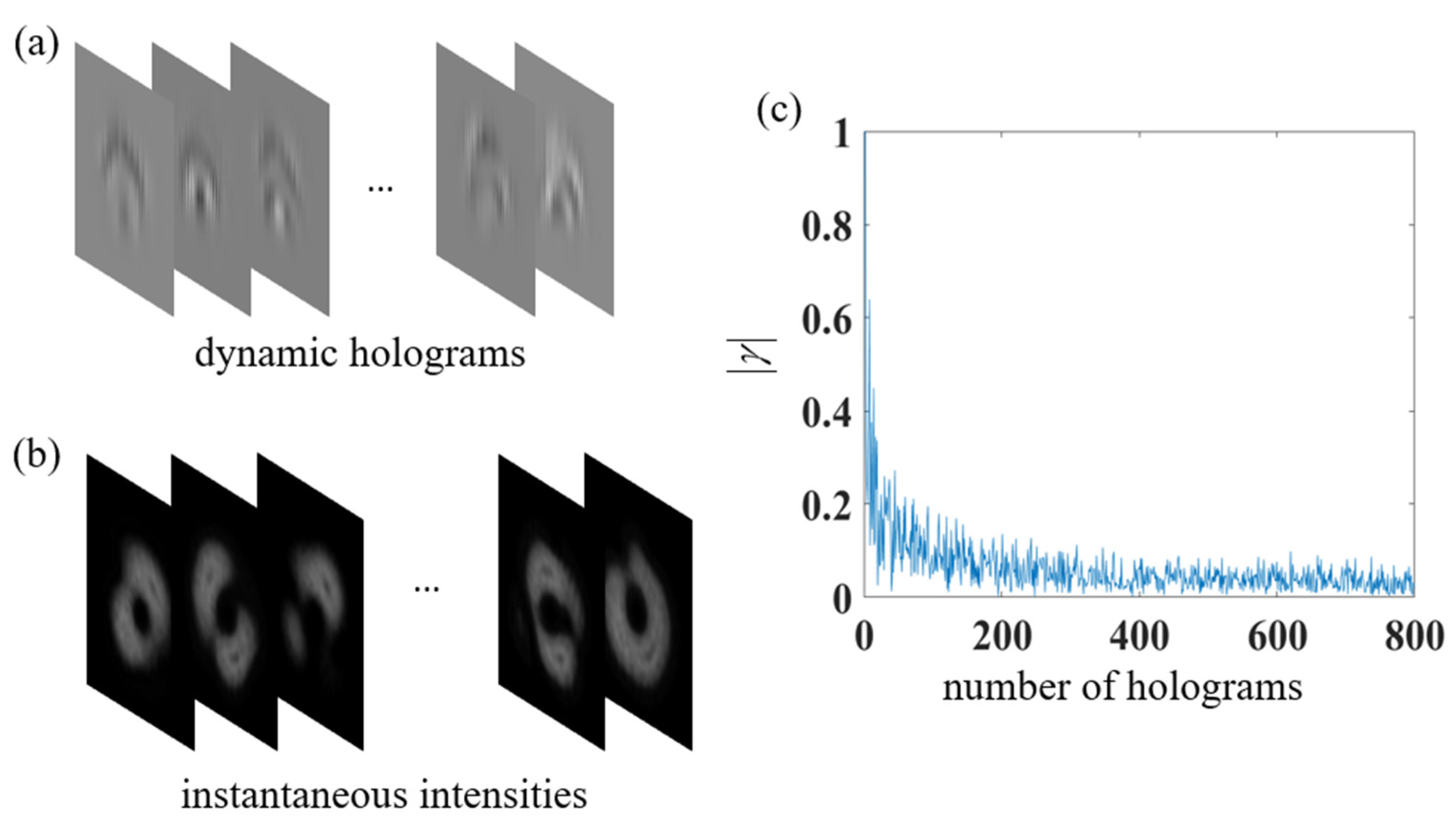
Figure 7a shows a set of frames of the dynamic holograms for generating a TLGSM beam with μ = 1.5 × 10 4   mm 1 and l = 2 . It should be emphasized here that each frame of the dynamic holograms is a complex phase pattern contributed by all the involved pseudo modes. We note that a large number of frames with random phases in the dynamic holograms is necessary to ensure that all the pseudo modes are mutually incoherent. To quantify the number of hologram frames, we calculate the absolute value of the degree of coherence (DOC) of the sampled pseudo modes, which is given by [44,49]
γ ( v m 1 n 1 , v m 2 n 2 ) = 1 T | t = 1 T exp [ i γ t ( v m 1 n 1 ) i γ t ( v m 2 n 2 ) ] | ( v m 1 n 1 v m 2 n 2 ) .
Figure 7c depicts the absolute value of the DOC between different modes versus the number T of the hologram frames. It is found that the correlation between different modes decreases rapidly with the increase in T and gradually fluctuates around a small value. In our experiment, 800 frames for the dynamic holograms are used since in such a case, the correlation between different pseudo modes can be neglected (i.e., | γ | 0.03 ) and the intensity distribution of the synthesized beam is relatively uniform. Figure 7b shows the experimentally captured instantaneous intensities for the optical modes ϕ t ( r ) . The final TLGSM source can be synthesized by averaging over the large number of instantaneous fields corresponding to the displayed dynamic hologram serials.
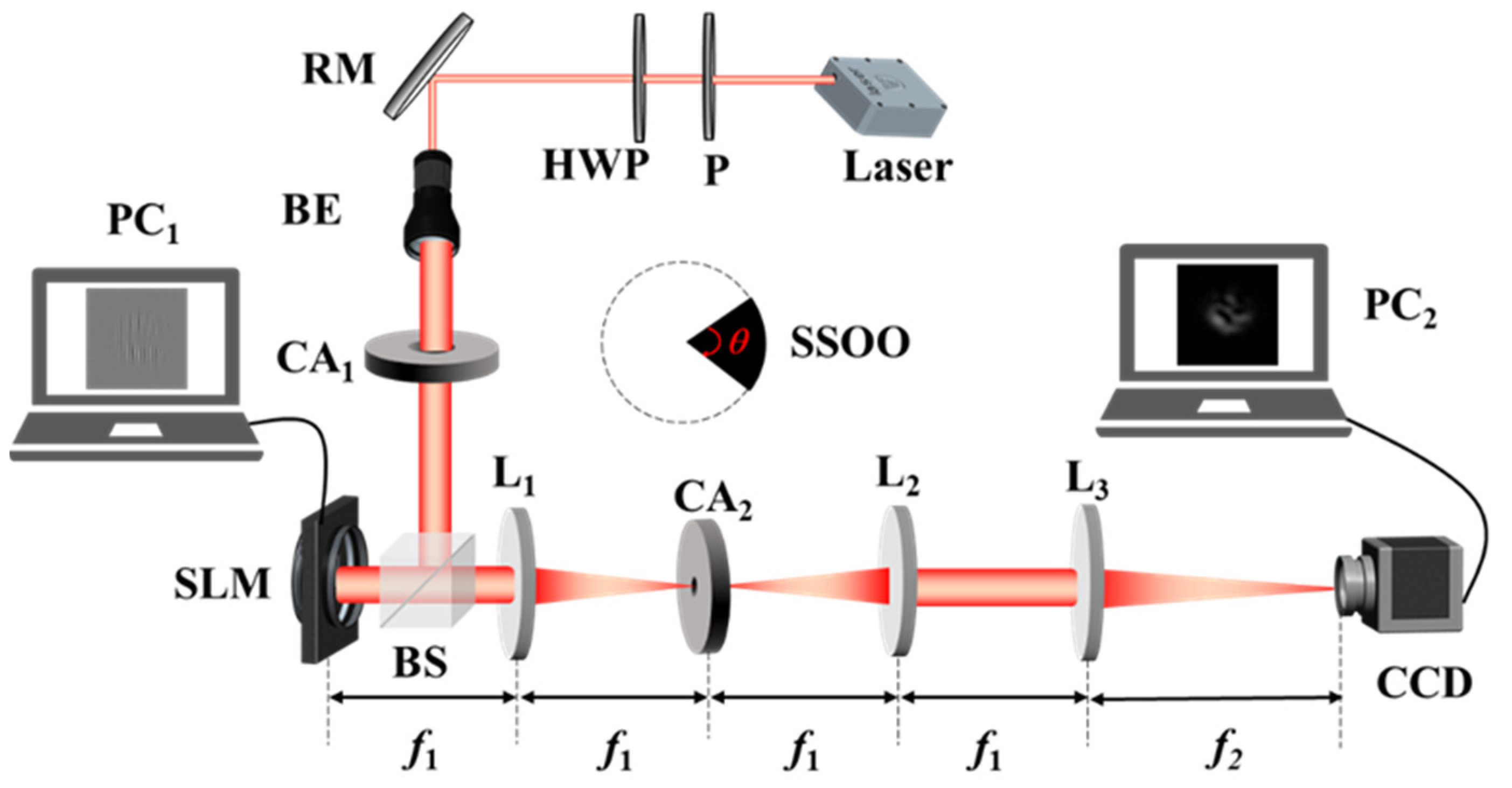
Figure 8 shows our experimental setup for generating a TLGSM beam. A fully coherent light emitted by a He-Ne laser with the wavelength λ = 632.8 nm passes through a linear polarizer (P) and a half-wave plate (HWP) successively. Next, it is reflected with a reflective mirror (RM) and expanded with a beam expander (BE). After the expanded beam is modulated with a circular aperture (CA1), it is divided with a beam splitter (BS). One portion reaches a reflective phase-only spatial-light modulator (SLM; Pluto, Holoeye). The dynamic holograms shown in Figure 7a are loaded on the SLM beforehand to generate the complex optical modes by Equation (10). It is worth noting that each frame of the displayed computer-generated hologram is a complex phase pattern determined by all involved pseudo modes with their corresponding random phases and weights. The difference between any two frames of the dynamic hologram is caused by the random phases. To ensure that all the modes are mutually uncorrelated, 800 hologram frames are prepared in advance. Next, the SLM plays 800 frames in a cycle, with each frame having the same time interval. In our experiment, the frame rate of the phase pattern sequence loaded to the SLM is about 10 fps, while the refreshing rate of the SLM used here is 60 Hz. Thus, the time needed for the SLM to switch from one hologram to the other is negligible compared to the playing time of each hologram on the SLM. The modulated beam after the SLM is transmitted through a 4 f imaging system formed by the thin lens L1, L2 and a circular aperture in the frequency plane to select out the first-order diffracted beam. Next, the TLGSM source is synthesized in the output plane of the 4 f imaging system, i.e., the rear focal plane of L2. We remark that the spatial coherence width δ 0 , the topological charge l , and the twist parameter μ of the TLGSM source can be controlled by modulating the dynamic hologram with the help of Equation (10). To examine the focusing properties, the TLGSM beam is focused by a thin lens L3 with focal distance f 3 = 400 mm. A charge-coupled device (CCD) camera is placed along the beam axis to record the intensities of the TLGSM beam at different propagation distances. The exposure time of the CCD camera can be controlled to capture the instantaneous intensities affiliated to each frame of the dynamic complex holograms. In our experiment, the synthesis of the TLGSM beam is based on the time-averaging of a series of pseudo modes. Therefore, the synthesized TLGSM beam makes sense only on a timescale that is determined by the playing time of 800 dynamic holograms. The efficiency for synthesizing a TLGSM beam can be further improved with a faster light modulator, such as a digital micro-mirror device (DMD) [50,51].
Figure 9 shows the experimental results of the average intensity distributions of the generated TLGSM beam at different propagation distances. We find that TLGSM beams with different twist factors have the same dark-hollow intensity distribution in the source because the intensity in the source plane is determined only by the phase singularity of a vortex phase. However, with the increase in the propagation distance, the dark-hollow beam profile of the TLGSM beam with μ = 0 degenerates into the quasi-Gaussian distribution. The twist phase with a positive or a negative twist factor speeds up or impedes this tendency. As a result, as shown in the right panels of Figure 9, the TLGSM beam with a positive μ shows a Gaussian beam spot in the focal plane and the TLGSM beam with a negative μ shows a dark-hollow beam profile in the focal plane. The experimental results are well consistent with the simulation results shown in Figure 4. We also notice an astigmatic effect in the intensity distributions, which may be corrected by applying a small tilt in the lens L3 [52,53].
In Figure 10, we exhibit the measured intensity distributions of the TLGSM beam obstructed by an SSOO with center angle α = π / 3 . From the experimental results, we find that the notch in the intensity distribution rotates during propagation. In the source plane, it faces the right direction, while in the focal plane, it rotates 90 degrees counterclockwise and faces the upward direction. In addition, it is found that the notch in the intensity distribution fades away in the focal plane when the twist parameter μ varies from negative to positive. When μ is controlled to be 1.5 × 10 4   mm 1 , the intensity distribution in the focal plane becomes a solid Gaussian beam spot, which reflects the self-reconstruction property of the intensity as the experimental results in Figure 9d and Figure 10d are compared.
We now turn to examine the influence of the twist phase on the self-reconstruction property of the spatial DOC of a TLGSM beam in the focal plane. The beam with μ = 0 and μ = 1.5 × 10 4   mm 1 is blocked by an SSOO with center angle α = 0 (without obstruction), α = π / 6 , and α = π / 3 , respectively. Figure 11 shows the experimental results of the measured spatial DOC | γ ( ρ , ρ ) | 2 in the focal plane of a TLGSM beam with different obstructions and different twist factors. The spatial DOC of the synthesized beam in our experiment is obtained via the equation
| γ ( ρ , ρ ) | 2 = t = 1 T I t ( ρ ) I t ( ρ ) t = 1 T I t ( ρ ) t = 1 T I t ( ρ ) ,
where I t ( ρ ) is the measured instantaneous intensities affiliated to each frame of dynamic complex holograms in the focal plane. The relation of Equation (12) is obtained with the uncorrelated property of the pseudo modes. It is found in Figure 11 that although the outside part of the distribution of the spatial DOC deteriorates due to the stray light, the strength of the bright side rings is enhanced evidently in the case of a positive value of the twist factor. In comparison to the spatial DOC of an obstructed beam with no twist phase ( μ = 0 ), the bright side rings can be distinguished clearly despite the growing area of obstruction. This result helps us improve the fidelity of quantifying the topological charge of a blocked partially coherent vortex beam. We remark here that the orbital angular momentum of a TLGSM beam is determined by both the topological charge of the vortex phase and the twist factor of the twisted phase, which can both be measured from the spatial coherence structure measurement of the beam [19,45]. The differences between the simulation and experimental results for the spatial degree of coherence may introduced from the division calculation shown in Equation (12).

4. Conclusions

In summary, we experimentally demonstrated a flexible and highly efficient method to generate a Gaussian Schell-model beam carrying both the vortex phase and the second-order twist phase. The method was based on the discrete pseudo-mode representation of a partially coherent twisted beam, in which we showed that all the required pseudo modes with the corresponding weights can be encoded into a single frame of a dynamic hologram by introducing random phases into the modes. It was demonstrated experimentally that by sequentially displaying the dynamic holograms on a single spatial-light modulator, a controllable twisted Laguerre–Gaussian Schell-model (TLGSM) beam can be synthesized. We also studied both numerically and experimentally the joint effect of the vortex phase and twist phase on the propagation and self-reconstruction characteristics of the intensity and spatial degree of coherence of the TLGSM beam with the help of the discrete pseudo-mode representation method. The results showed that the preservation of the donut shape intensity distribution of a partially coherent vortex beam with a positive topological charge during propagation can be enhanced with the twist phase having a negative twist factor. The self-reconstruction properties of the focal-plane intensity and spatial degree of coherence of an obstructed TLGSM beam can also be enhanced with the twist phase having a positive twist factor. The enhancement of the spatial degree of coherence can be used for improving the identification reliability of the topological charge for partially coherent vortex beams. Our results verified the combined effect of the twist and vortex phases and provide an effective way to synthesize partially coherent beams with novel coherence phases.

Author Contributions

Conceptualization, L.L.; funding acquisition, L.L., Y.C. (Yahong Chen), F.W. and Y.C. (Yangjian Cai); investigation, Y.X. and H.W.; project administration, L.L., Y.C. (Yahong Chen), F.W. and Y.C. (Yangjian Cai); software, Y.X. and H.W.; supervision, L.L., F.W. and Y.C. (Yangjian Cai); validation, Y.C. (Yahong Chen); writing—original draft, Y.X. and H.W.; writing—review and editing, L.L., Y.C. (Yahong Chen) and F.W. All authors have read and agreed to the published version of the manuscript.

Funding

This research was funded by the National Key Research and Development Program of China (grant nos. 2022YFA1404800 and 2019YFA0705000), the National Natural Science Foundation of China (grant nos. 12192254, 92250304, 11974218, 11904247, 12274310, and 12174279), and the Local Science and Technology Development Project of the Central Government (grant no. YDZX20203700001766).

Institutional Review Board Statement

Not applicable.

Informed Consent Statement

Not applicable.

Data Availability Statement

The data presented in this study are available upon request from the corresponding author.

Conflicts of Interest

The authors declare no conflict of interest.

References

  1. Mandel, L.; Wolf, E. Optical Coherence and Quantum Optics; Cambridge University Press: Cambridge, UK, 1995. [Google Scholar]
  2. Friberg, A.T.; Setälä, T. Electromagnetic theory of optical coherence. J. Opt. Soc. Am. A 2016, 33, 2431–2442. [Google Scholar] [CrossRef] [PubMed]
  3. Chen, Y.; Cai, Y. Optical coherence structure: A novel tool for light manipulation. Sci. China Technol. Sci. 2022, 65, 740–742. [Google Scholar] [CrossRef]
  4. Korotkova, O.; Chen, X. Phase structuring of the complex degree of coherence. Opt. Lett. 2018, 43, 4727–4730. [Google Scholar] [CrossRef] [PubMed]
  5. Chen, X.; Korotkova, O. Complex degree of coherence modeling with famous planar curves. Opt. Lett. 2018, 43, 6049–6052. [Google Scholar] [CrossRef]
  6. Chen, X.; Korotkova, O. Phase structuring of 2D complex coherence states. Opt. Lett. 2019, 44, 2470–2473. [Google Scholar] [CrossRef]
  7. Korotkova, O. Multi-Gaussian Schell-model source with a complex coherence. J. Opt. 2019, 21, 045607. [Google Scholar] [CrossRef]
  8. Chen, Y.; Ponomarenko, S.A.; Cai, Y. Experimental generation of optical coherence lattices. Appl. Phys. Lett. 2016, 109, 061107. [Google Scholar] [CrossRef] [Green Version]
  9. Wan, L.; Zhao, D. Controllable rotating Gaussian Schell-model beams. Opt. Lett. 2019, 44, 735–738. [Google Scholar] [CrossRef]
  10. Wan, L.; Zhao, D. Generalized partially coherent beams with nonseparable phases. Opt. Lett. 2019, 44, 4714–4717. [Google Scholar] [CrossRef]
  11. Pan, R.; Liu, X.; Tang, J.; Ye, H.; Liu, Z.; Ma, P.; Wen, W.; Hoenders, B.J.; Cai, Y.; Liang, C. Enhancing the self-reconstruction ability of the degree of coherence of a light beam via manipulating the cross-phase structure. Appl. Phys. Lett. 2021, 119, 111105. [Google Scholar] [CrossRef]
  12. Jin, Y.; Wang, H.; Liu, L.; Chen, Y.; Wang, F.; Cai, Y. Orientation-selective sub-Rayleigh imaging with spatial coherence lattices. Opt. Express 2022, 30, 9548–9561. [Google Scholar] [CrossRef]
  13. Chen, Y.; Ponomarenko, S.; Cai, A.Y. Self-steering partially coherent beams. Sci. Rep. 2017, 7, 39957. [Google Scholar] [CrossRef] [PubMed]
  14. Huang, Z.; Chen, Y.; Wang, F.; Ponomarenko, S.A.; Cai, Y. Measuring complex degree of coherence of random light fields with generalized Hanbury Brown–Twiss experiment. Phys. Rev. Appl. 2020, 13, 044042. [Google Scholar] [CrossRef]
  15. Dong, Z.; Huang, Z.; Chen, Y.; Wang, F.; Cai, Y. Measuring complex correlation matrix of partially coherent vector light via a generalized Hanbury Brown–Twiss experiment. Opt. Express 2020, 28, 20634–20644. [Google Scholar] [CrossRef] [PubMed]
  16. Peng, D.; Huang, Z.; Liu, Y.; Chen, Y.; Wang, F.; Ponomarenko, S.A.; Cai, Y. Optical coherence encryption with structured random light. PhotoniX 2021, 2, 6. [Google Scholar] [CrossRef]
  17. Liu, Y.; Chen, Y.; Wang, F.; Cai, Y.; Liang, C.; Korotkova, O. Robust far-field imaging by spatial coherence engineering. Opto-Electron. Adv. 2021, 4, 210027. [Google Scholar] [CrossRef]
  18. Liu, Y.; Zhang, X.; Dong, Z.; Peng, D.; Chen, Y.; Wang, F.; Cai, Y. Robust Far-Field Optical Image Transmission with Structured Random Light Beams. Phys. Rev. Appl. 2022, 17, 024043. [Google Scholar] [CrossRef]
  19. Dong, M.; Zhao, C.; Cai, Y.; Yang, Y. Partially coherent vortex beams: Fundamentals and applications. Sci. China Phys. Mech. Astron. 2021, 64, 224201. [Google Scholar] [CrossRef]
  20. Simon, R.; Mukunda, N. Twisted Gaussian Schell-model beams. J. Opt. Soc. Am. A 1993, 10, 95–109. [Google Scholar] [CrossRef]
  21. Cai, Y.; Lin, Q.; Korotkova, O. Ghost imaging with twisted Gaussian Schell-model beam. Opt. Express 2009, 17, 2453–2464. [Google Scholar] [CrossRef]
  22. Zhao, C.; Cai, Y.; Korotkova, O. Radiation force of scalar and electromagnetic twisted Gaussian Schell-model beams. Opt. Express 2009, 17, 21472–21487. [Google Scholar] [CrossRef] [PubMed]
  23. Wang, F.; Cai, Y.; Eyyuboğlu, H.T.; Baykal, Y. Twist phase-induced reduction in scintillation of a partially coherent beam in turbulent atmosphere. Opt. Lett. 2012, 37, 184–186. [Google Scholar] [CrossRef] [PubMed]
  24. Tong, Z.; Korotkova, O. Beyond the classical Rayleigh limit with twisted light. Opt. Lett. 2012, 37, 2595–2597. [Google Scholar] [CrossRef] [PubMed]
  25. Allen, L.; Beijersbergen, M.W.; Spreeuw, R.J.C.; Woerdman, J.P. Orbital angular momentum of light and the transformation of Laguerre-Gaussian laser modes. Phys. Rev. A 1992, 45, 8185–8189. [Google Scholar] [CrossRef]
  26. Padgett, M.J. Orbital angular momentum 25 years on. Opt. Express 2017, 25, 11265–11274. [Google Scholar] [CrossRef]
  27. Trichili, A.; Salem, A.B.; Dudley, A.; Zghal, M.; Forbes, A. Encoding information using Laguerre Gaussian modes over free space turbulence media. Opt. Lett. 2016, 41, 3086–3089. [Google Scholar] [CrossRef] [PubMed] [Green Version]
  28. Wang, J.; Yang, J.; Fazal, I.M.; Ahmed, N.; Yan, Y.; Huang, H.; Ren, Y.; Dolinar, S.; Tur, M.; Willner, A.E. Terabit free-space data transmission employing orbital angular momentum multiplexing. Nat. Photonics 2012, 6, 488–496. [Google Scholar] [CrossRef]
  29. Willig, K.I.; Rizzoli, S.O.; Westphal, V.; Jahn, R.; Hell, S.W. STED microscopy reveals that synaptotagmin remains clustered after synaptic vesicle exocytosis. Nature 2006, 440, 935–939. [Google Scholar] [CrossRef]
  30. Wang, B.; Brooks, N.J.; Johnsen, P.C.; Jenkins, N.W.; Esashi, Y.; Binnie, I.; Tanksalvala, M.; Kapteyn, H.C.; Murnane, M.M. High-fidelity ptychographic imaging of highly periodic structures enabled by vortex high harmonic beams. arXiv 2023, arXiv:2301.05563. [Google Scholar]
  31. Roxworthy, B.J.; Toussaint, K.C. Optical trapping with π-phase cylindrical vector beams. New J. Phys. 2010, 12, 073012. [Google Scholar] [CrossRef]
  32. Li, Z.; Liu, T.; Ren, Y.; Qiu, S.; Wang, C.; Wang, H. Direction-sensitive detection of a spinning object using dual-frequency vortex light. Opt. Express 2021, 29, 7453–7463. [Google Scholar] [CrossRef]
  33. Wang, B.; Tanksalvala, M.; Zhang, Z.; Murnane, M.; Kapteyn, H.; Liao, C. Coherent Fourier scatterometry using orbital angular momentum beams for defect detection. Opt. Express 2021, 29, 3342–3358. [Google Scholar] [CrossRef]
  34. Mccarter, M.R.; Saleheen, A.; Singh, A.; Tumbleson, R.; Woods, J.S.; Tremsin, A.S.; Scholl, A.; De Long, L.E.; Hastings, J.T.; Morley, S.A.; et al. Antiferromagnetic real-space configuration probed by x-ray orbital angular momentum phase dichroism. arXiv 2022, arXiv:2205.03475. [Google Scholar]
  35. Ponomarenko, S.A. Twist phase and classical entanglement of partially coherent light. Opt. Lett. 2021, 46, 5958–5961. [Google Scholar] [CrossRef] [PubMed]
  36. Ponomarenko, S.A. Classical entanglement of twisted random light propagating through atmospheric turbulence. J. Opt. Soc. Am. 2022, 39, C1–C5. [Google Scholar] [CrossRef] [PubMed]
  37. Serna, J.; Movilla, J.M. Orbital angular momentum of partially coherent beams. Opt. Lett. 2001, 26, 405–407. [Google Scholar] [CrossRef] [PubMed] [Green Version]
  38. Liu, L.; Huang, Y.; Chen, Y.; Guo, L.; Cai, Y. Orbital angular moment of an electromagnetic Gaussian Schell-model beam with a twist phase. Opt. Express 2015, 23, 30283–30296. [Google Scholar] [CrossRef]
  39. Peng, X.; Liu, L.; Wang, F.; Popov, S.; Cai, Y. Twisted Laguerre-Gaussian Schell-model beam and its orbital angular moment. Opt. Express 2018, 26, 33956–33969. [Google Scholar] [CrossRef]
  40. Peng, X.; Wang, H.; Liu, L.; Wang, F.; Popov, S.; Cai, Y. Self-reconstruction of twisted Laguerre-Gaussian Schell-model beams partially blocked by an opaque obstacle. Opt. Express 2020, 28, 31510–31523. [Google Scholar] [CrossRef]
  41. Friberg, A.T.; Tervonen, E.; Turunen, J. Interpretation and experimental demonstration of twisted Gaussian Schell-model beams. J. Opt. Soc. Am. A 1994, 11, 1818–1826. [Google Scholar] [CrossRef]
  42. Wang, H.; Peng, X.; Liu, L.; Wang, F.; Cai, Y.; Ponomarenko, S.A. Generating bona fide twisted Gaussian Schell-model beams. Opt. Lett. 2019, 44, 3709–3712. [Google Scholar] [CrossRef] [PubMed]
  43. Zhang, Y.; Zhang, X.; Wang, H.; Ye, Y.; Liu, L.; Chen, Y.; Wang, F.; Cai, Y. Generating a twisted Gaussian Schell-model beam with a coherent-mode superposition. Opt. Express 2021, 29, 41964–41974. [Google Scholar] [CrossRef]
  44. Tian, C.; Zhu, S.; Huang, H.; Cai, Y.; Li, Z. Customizing twisted Schell-model beams. Opt. Lett. 2020, 45, 5880–5883. [Google Scholar] [CrossRef] [PubMed]
  45. Wang, H.; Peng, X.; Zhang, H.; Liu, L.; Chen, Y.; Wang, F.; Cai, Y. Experimental synthesis of partially coherent beam with controllable twist phase and measuring its orbital angular momentum. Nanophotonics 2022, 11, 689–696. [Google Scholar] [CrossRef]
  46. Wang, F.; Lv, H.; Chen, Y.; Cai, Y.; Korotkova, O. Three modal decompositions of Gaussian Schell-model sources: Comparative analysis. Opt. Express 2021, 29, 29676–29689. [Google Scholar] [CrossRef]
  47. Gori, F.; Santarsiero, M. Devising genuine spatial correlation functions. Opt. Lett. 2007, 32, 3531–3533. [Google Scholar] [CrossRef] [Green Version]
  48. Collins, S.A. Lens-System Diffraction Integral Written in Terms of Matrix Optics. J. Opt. Soc. Am. 1970, 60, 1168–1177. [Google Scholar] [CrossRef]
  49. Wang, R.; Zhu, S.; Chen, Y.; Huang, H.; Li, Z.; Cai, Y. Experimental synthesis of partially coherent sources. Opt. Lett. 2020, 45, 1874–1877. [Google Scholar] [CrossRef]
  50. Zhu, X.; Yu, J.; Chen, Y.; Wang, F.; Korotkova, O.; Cai, Y. Experimental synthesis of random light sources with circular coherence by digital micro-mirror device. Appl. Phys. Lett. 2020, 117, 121102. [Google Scholar] [CrossRef]
  51. Zhu, X.; Yu, J.; Wang, F.; Chen, Y.; Cai, Y.; Korotkova, O. Synthesis of vector nonuniformly correlated light beams by a single digital mirror device. Opt. Lett. 2021, 46, 2996–2999. [Google Scholar] [CrossRef] [PubMed]
  52. Vaity, P.; Banerji, J.; Singh, R. Measuring the topological charge of an optical vortex by using a tilted convex lens. Phys. Lett. A 2013, 377, 1154–1156. [Google Scholar] [CrossRef]
  53. da Silva, B.P.; Tasca, D.S.; Galvão, E.F.; Khoury, A.Z. Astigmatic tomography of orbital-angular-momentum superpositions. Phys. Rev. A 2019, 99, 043820. [Google Scholar] [CrossRef] [Green Version]
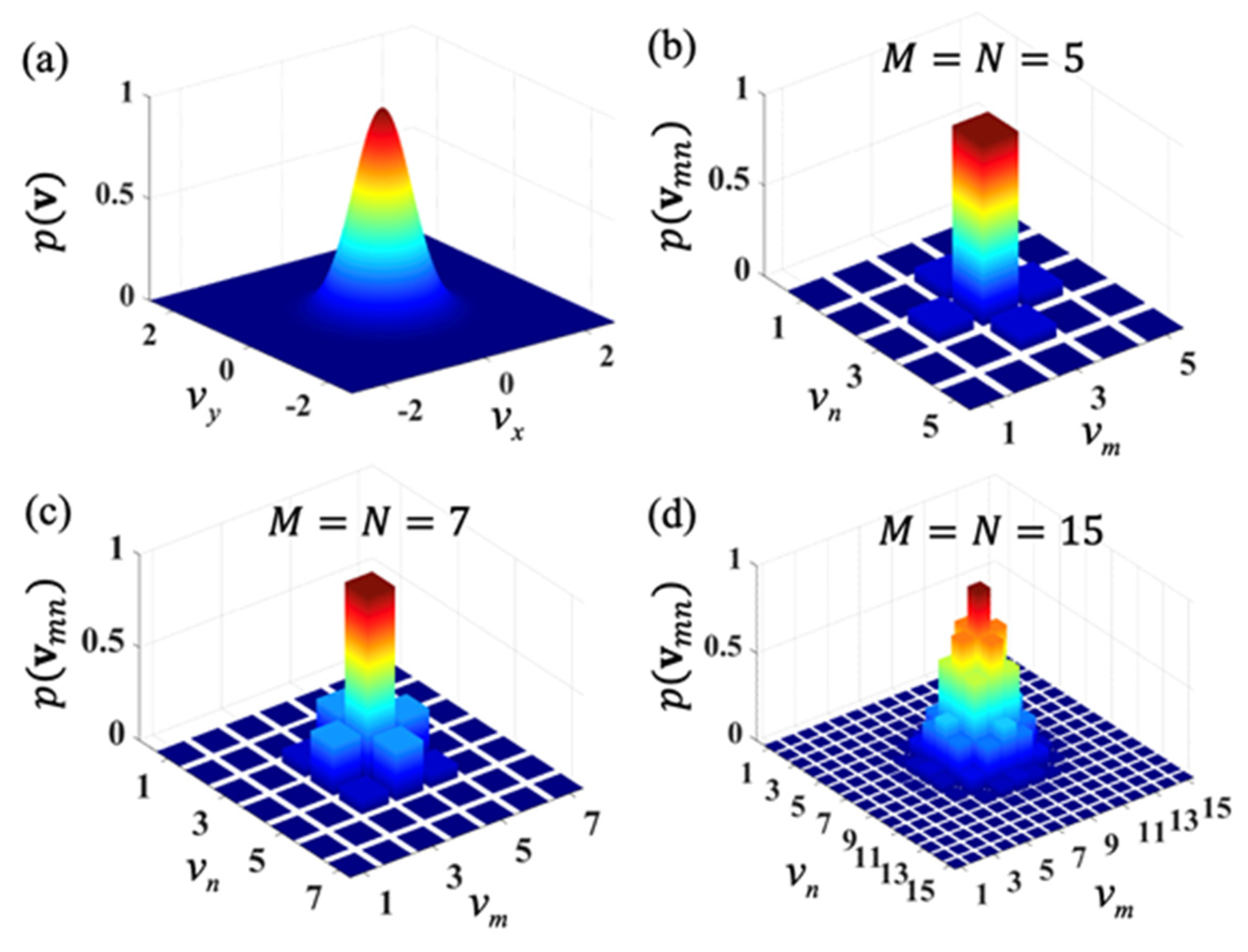
Figure 1. (a) The spatial distribution of the weight function p ( v ) . (bd) The variation of the discrete function p ( v m n ) with indices m and n when the total number of the discrete modes is selected as (b) M = N = 5 , (c) M = N = 7 , and (d) M = N = 15 .
Photonics 10 00314 g001
Figure 2. The spatial distributions for the spectral density of a beam synthesized with (a) M × N = 5 × 5 pseudo modes, (b) M × N = 7 × 7 pseudo modes, and (c) M × N = 15 × 15 pseudo modes. The red curves in (df) show the corresponding cross line ( y = 0 ) of the simulation results, while the dotted black curves show the corresponding theoretical results.
Photonics 10 00314 g002
Figure 3. The spatial distributions for the spatial degree of coherence | γ ( r , r ) | of a beam synthesized with (a) M × N = 5 × 5 pseudo modes, (b) M × N = 7 × 7 pseudo modes, and (c) M × N = 15 × 15 pseudo modes. The red curves in (df) show the corresponding cross line ( y = 0 ) of the simulation results, while the dotted black curves show the corresponding theoretical results.
Photonics 10 00314 g003
Figure 4. The simulation results for the spectral density at different propagation distances of a TLGSM beam with (ad) the twist factor μ = 1.5 × 10 4   mm 1 , (eh) μ = 0 , and (il) μ = 1.5 × 10 4   mm 1 .
Photonics 10 00314 g004
Figure 5. The simulation results for the spectral density at different propagation distances of a TLGSM beam with (ad) the twist factor μ = 1.5 × 10 4   mm 1 , (eh) μ = 0 , and (il) μ = 1.5 × 10 4   mm 1 . The TLGSM beam is obstructed by a sector-shaped opaque obstacle with center angle α = π / 3 .
Photonics 10 00314 g005
Figure 6. The simulation results for the spatial degree of coherence | γ ( ρ , ρ ) | 2 in the focal plane of a TLGSM beam with (ac) the twist factor μ = 1.5 × 10 4   mm 1 and (df) μ = 0 . The TLGSM beam is obstructed by a sector-shaped opaque obstacle with center angle (a,d) α = 0 , (b,e) α = π / 6 , and (c,f) α = π / 3 .
Photonics 10 00314 g006
Figure 7. (a) A schematic illustration of the dynamic computer-generated hologram. (b) The experimental results of the instantaneous intensities for the dynamic hologram. (c) The absolute value of the degree of coherence | γ | between different modes versus the number T of the hologram frames.
Photonics 10 00314 g007
Figure 8. Experimental setup for generating a TLGSM beam. Laser, He-Ne laser; P, linear polarizer; HWP, half-wave plate; RM, reflecting mirror; BE, beam expander; CA1, CA2, circular apertures; BS, beam splitters; SLM, spatial-light modulator; L1, L2, L3, thin lenses; CCD, charge-coupled device; PC1, PC2, personal computers.
Photonics 10 00314 g008
Figure 9. The experimental results for the averaged intensity at different propagation distances of the generated TLGSM beam with (ad) the twist factor μ = 1.5 × 10 4   mm 1 , (eh) μ = 0 , and (il) μ = 1.5 × 10 4   mm 1 .
Photonics 10 00314 g009
Figure 10. The experimental results for the averaged intensity at different propagation distances of the generated TLGSM beam with (ad) the twist factor μ = 1.5 × 10 4   mm 1 , (eh) μ = 0 , and (il) μ = 1.5 × 10 4   mm 1 . The TLGSM beam is obstructed by a sector-shaped opaque obstacle with center angle α = π / 3 .
Photonics 10 00314 g010
Figure 11. The experimental results for the spatial degree of coherence | γ ( ρ , ρ ) | 2 in the focal plane of the generated TLGSM beam with (ac) the twist factor μ = 1.5 × 10 4   mm 1 and (df) μ = 0 . The TLGSM beam is obstructed by a sector-shaped opaque obstacle with center angle (a,d) α = 0 , (b,e) α = π / 6 , and (c,f) α = π / 3 .
Photonics 10 00314 g011
Disclaimer/Publisher’s Note: The statements, opinions and data contained in all publications are solely those of the individual author(s) and contributor(s) and not of MDPI and/or the editor(s). MDPI and/or the editor(s) disclaim responsibility for any injury to people or property resulting from any ideas, methods, instructions or products referred to in the content.