Article

Three-Dimensional Mapping Technology for Structural Deformation during Aircraft Assembly Process

1
School of Optoelectronic Engineering, Changchun University of Science and Technology, Changchun 130022, China
2
Zhongshan Institute of Changchun University of Science and Technology, Zhongshan 528400, China
*
Author to whom correspondence should be addressed.
Photonics 2023, 10(3), 318; https://doi.org/10.3390/photonics10030318
Submission received: 8 February 2023 / Revised: 13 March 2023 / Accepted: 14 March 2023 / Published: 16 March 2023
(This article belongs to the Topic Manufacturing Metrology)

Abstract

:
Owing to the assembly state changes during aircraft assembly processes, assembly force-deformation problem occurs. To obtain the structure shape in the product assembly process efficiently and accurately, a three-dimensional (3D) mapping technology for the structural deformation during the aircraft assembly process is proposed combined with a fiber Bragg grating (FBG) optical fiber sensor and binocular vision measurement system. First, this study established a curvature transformation model using optical fiber monitoring data, obtained the 3D spatial deformation of the product, and completed the unification of the optical fiber wavelength change and spatial 3D point coordinate heterogeneous data. Second, a mesh deformation optimization algorithm based on point-cloud optimization was established. Subsequently, the deformation effects of four mesh deformation models were compared to verify the feasibility and accuracy of HEC-Laplace, and the 3D mapping of the product structure shape in the assembly process was realized. Finally, a cantilever wing model was used to verify the deformation of different loading modes. The results show that the product structure changes can be accurately obtained through the proposed technology, thereby improving the accuracy control and overall assembly quality in the aircraft assembly process and providing a theoretical basis for intelligent aircraft assembly.

1. Introduction

With the introduction and popularization of a series of international strategic plans, such as “Industry 4.0” and “Made in China 2025,” manufacturing technologies of large equipment have been facing unprecedented opportunities and challenges. Among them, the intelligent assembly of aircraft is particularly important as the final link of performance guarantee in the product development process.
An aircraft structure is complex, and aircraft assembly is a typical discrete type of assembly characterized by manual assembly, process-oriented production, and assembly, including a wide variety and range of parts and professional fields, emphasizing product plasticity, multiple reworks, and repairs. During the aircraft assembly process, owing to the manufacturing deviation of components and defects of the assembly process, a series of problems, such as repeatability, randomness, instability, and excessive reworks and repairs often produce assembly stress. This causes the deformation of the key assembly positions, thereby affecting the subsequent assembly accuracy and overall assembly quality of the aircraft, and reducing its stability and safety. Therefore, preserving the actual structural form during the assembly process is particularly important for the aircraft.
Today, with the continuous innovations in detection technologies, the methods to implement digital measurement technologies are gradually increasing. For structural detection during aircraft assembly, visual-measurement [1], coordinate-measurement [2], laser-scanning [3], strain-gauge measurement [4], and sensor-detection methods have been used. Wang [5] combined a laser-tracking and laser-scanning system to obtain the structural data of a wing panel and evaluated the clearance fit of the assembly model. For complex assembly products, Zhang [6] used laser-scanning technology to obtain the measured data to detect the product distortion or deviation for conducting assembly interference research. Guo [7] analyzed the status of the assembly technology driven by digital twins. Considering the skin as an example, the distortion of skin surface was detected by structured light scanning technology, and a twin process model was built. Sun [8] used optical fiber sensors to sense the three-dimensional (3D) shape of a flexible deformed wing, analyzed the relationship between the optical fiber detection data and wing shape, and reconstructed the 3D shape of the wing skin by interpolation. Ma [9] designed two sets of aluminium alloy test plates of different sizes as matrix materials for tensile testing of the strain sensitivity of fiber Bragg grating (FBG) for measuring wing deformation. Therefore, digital measurements have been widely used in the aircraft assembly processes. Among them, the laser-scanning method can accurately and effectively obtain high-precision and high-density point-cloud data, and is less affected by space and environment. It is a stable and direct method to reflect the actual state of the model, and is widely used in various industries. However, for structural deformation detection during the aircraft assembly process, the laser-scanning method is inefficient and affects the overall assembly process. Simultaneously, owing to the shielding of the frame-tooling structure, positioner, personnel, and equipment, the key position feature information of the assembly cannot be obtained, and it is easy to cause secondary damage to the assembly during the repeated measurement process. Considering the abovementioned situation, for structural deformation monitoring, the sensor-detection method has significant advantages such as small size, lightweight, high sensitivity, short response time, and other characteristics. In comparison with the laser-scanning method, it can efficiently obtain structural deformation information in real time, and compensate for incomplete measurement data caused by the occlusion of the on-site objects in the laser-scanning method, which has had a wide application in the aerospace field [10,11,12,13,14]. However, the FBG sensor is a single-point measurement method, which can only obtain single-point information of the structure to be monitored. Therefore, it is inferior to the laser-scanning method in obtaining detailed features of complex structures.
Therefore, to obtain deformation data of complex structures with multiple geometric features efficiently and accurately, the laser-scanning and sensor-detection methods were combined to obtain the initial point-cloud data of an aircraft structure at the initial stage of assembly. Then, the optical fiber sensor was pasted in the deformable area to obtain optical fiber monitoring data under different assembly states to achieve rapid, accurate, and efficient acquisition of aircraft structural data under different assembly states, and maximize the advantages of their sensors. Thus, the main objective of this paper is to solve the unification of the 3D point-cloud data and optical fiber waveform data.
This study proposes a 3D mapping technology of structural deformation for aircraft assembly process. First, 3D point-cloud data of an aircraft surface structure were obtained based on the laser-scanning method. Second, the relationship between the aircraft optical fiber monitoring waveform information and the shape variables was deduced using the tangent recurrence method based on a quasi-distributed optical fiber sensor to obtain the aircraft optical fiber monitoring waveform data under different assembly conditions. Third, the half-edge folding method was introduced to optimize the Laplacian mesh deformation algorithm (HEC-Laplace), and a mesh deformation algorithm based on point-cloud optimization was constructed [15]. In addition, the feasibility and accuracy of HEC-Laplace was verified by comparing the deformation of surfaces with different curvatures using interpolation, Gaussian-fusion, and Laplace algorithms. Finally, based on a simple model of an aircraft wing, the proposed methods were verified in practice to realize the 3D mapping of the aircraft-wing structural deformation, improve the accuracy control and overall assembly quality in the aircraft assembly process, and provide a theoretical basis for intelligent aircraft assembly.

2. General Scheme

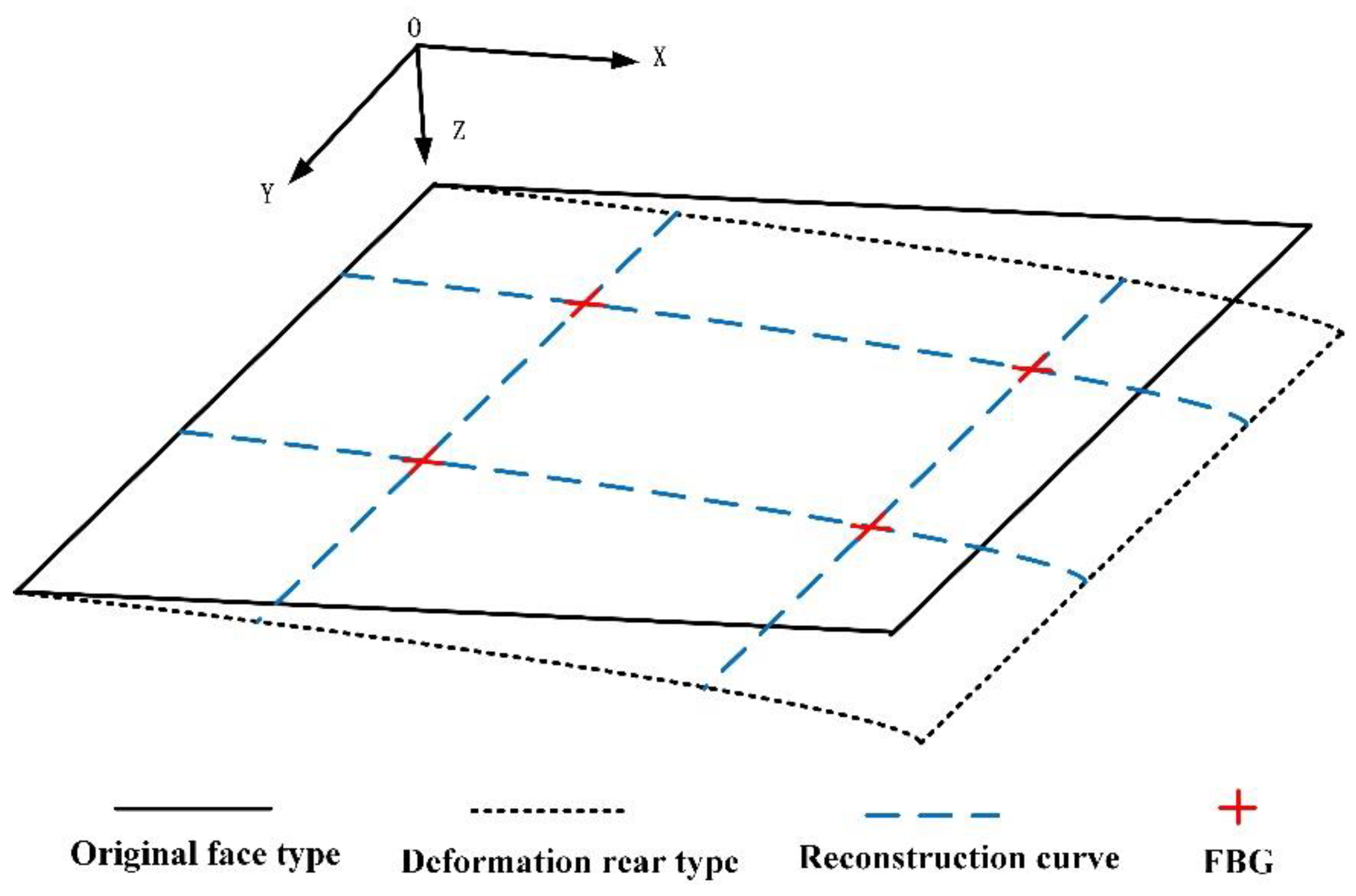
The structural deformation in the product assembly process has a great impact on the subsequent assembly accuracy control and overall assembly quality of the product. To obtain the structural deformation in the product assembly process quickly, efficiently, and accurately, a 3D mapping technology for structural deformation is proposed. The overall scheme is shown in Figure 1. The specific implementation steps are described as follows. First, we obtained 3D point-cloud and optical fiber monitoring waveform data based on a binocular vision measurement system and quasi-distributed fiber grating monitoring system to establish a high-fidelity model based on measured data. Because the data sources were significantly different and the data structure was of unequal valence, the measured data in the model were characterized by “multi-source heterogeneity.” Second, according to the waveform data obtained from optical fiber monitoring, the conversion relationship between the waveform data and spatial 3D point coordinate data was deduced by using the tangent recurrence method. Third, we established a mesh deformation model based on point-cloud optimization, and compared the deformation effects of four mesh deformation models based on the unequal curvature surface to verify the feasibility and accuracy of HEC-Laplace. Lastly, the feasibility of 3D mapping technology was verified through comparison and structural deformation experiments, which could provide a theoretical basis for precision control in the product assembly process and improve the overall assembly quality of products.

3. Methods

3.1. Curvature Conversion Model of Optical Fiber Monitoring

3.1.1. Curvature Conversion Model

Here, an FBG sensor was used to monitor the deformation of complex surfaces [16]. When light with a certain width and frequency was incident on the FBG fiber channel and passed through the grating area, the light wave with a frequency near the grating would be reflected back, whereas the light wave with other frequencies would pass through the FBG sensor. The resonance equation of FBG is expressed as
λ B = 2 n e f f Λ ,
where λ B is the central wavelength of the grating, n e f f is the effective refractive index of the fiber, and Λ  is the grating period.
The central wavelength λ B of FBG was mainly affected by temperature and strain. Assuming that the ambient temperature of the grating remained unchanged when it was subjected to axial stress ε , the change of the grating center wavelength caused by uniform axial strain Δ λ B is expressed as follows:
Δ λ B = λ B 1 P ε ε ,
where P ε represents the effective elastic and optical coefficient.
It can be seen that the shift of grating wavelength has a linear relationship with its axial strain. Simultaneously, at constant laboratory temperature, the change of FBG center wavelength was only affected by strain. The measured point of FBG could be modeled as a deformed beam with circular section. When the FBG sensor was subjected to axial strain, one surface of the deformed beam was stretched and the other surface was compressed. Because the area under tension was extended and the area under compression was shortened, the length of a layer in the middle remained unchanged, i.e., the strain was 0, which was called the strain neutral layer.
We assumed that L is the length of the element, Δ L is the change of the length of the structural element, ρ is the radius of curvature, and θ is the center angle of the arc, as shown in Figure 2. The following equations can be obtained:
L = ρ θ L + Δ L = ρ + h / 2 θ L Δ L = ρ h / 2 θ ε = Δ L / L .
By solving the above equations, we obtain
k = 1 ρ = 2 ε h ,
where k is the curvature, and ρ is the reciprocal of the radius of curvature. After combining Equations (2) and (4), the relationship between curvature and central wavelength drift is expressed as
k = 2 Δ λ B λ B 1 P ε h .
For any determined FBG, its λ B , P ε , and h are constant; thus, the curvature k is linear with the wavelength drift Δ λ B .

3.1.2. Coordinate Value Derivation Based on Curvature

It can be seen from the above derivation that the curvature k is linear with the wavelength drift Δ λ B , which was monitored by the FBG sensor. As shown in Figure 3, the curvature at the FBG monitoring points is discrete. To increase the number of data points, it was necessary to first carry out continuous processing of curvature, i.e., curvature interpolation between two adjacent measuring points. When the two points on the curve were close enough, the curve formed by the two points could be considered as an arc, so that the coordinate points on the curve could be derived by relevant methods, i.e., the point coordinates on the deformed surface, to provide point coordinate data for subsequent data fusion.
We set up a coordinate system by taking the A B segment of the deformed curve arc, as shown in Figure 4. The starting point A of the curve coincides with the origin of the coordinate, where A and B are tangent vectors of points A and B , respectively; θ i and θ i + 1 are tangent vectors of points A and B , respectively, at the positive angle to the X-axis, S n is the arc length of the curve arc, l a b is the chord length of the arc, and Δ θ is the central angle of the arc A B . For point A , the coordinate increment of point B is ( Δ x , Δ y ) .
Generally, θ can be obtained from the integral of curvature, as follows:
θ s = k s d s .
In Figure 4, Δ θ is the central angle of a circular arc segment, which can be derived from its geometric relationship as follows:
Δ θ = 180 90 θ i 180 90 θ i + 1 = θ i + θ i + 1 .
Chord length l a b is
l a b = 2 sin Δ θ 2 × r A B ,
where r A B is the radius of curvature of the arc and can be expressed by the curvature of points A and B :
r A B = r A + r B 2 = 1 k A + 1 k B 2 = k A + k B 2 k A k B .
Thus, we obtain
Δ x = l a b cos θ i Δ θ 2 Δ y = l a b sin θ i Δ θ 2 .
From the above equation, the following can be deduced:
x b = x a + Δ x y b = y a + Δ y .

3.2. Grid Distortion Optimization Algorithm for Base Point-Cloud Optimization

The nature of Laplacian mesh distortion is the encoding and decoding of local details of the mesh model. The main concept is to obtain local information, including size and direction at each vertex through differential coordinate transformation, and achieve the distortion of a 3D model, while keeping the local information unchanged. The concept of Laplacian mesh deformation technology determines the conflict between the number of vertices and efficiency of deformation. To solve this problem, a Laplacian deformation technology based on point-cloud optimization was proposed. The specific steps are described as follows.
  • Based on the optimized half-edge folding method, the original mesh model was simplified to obtain an optimized mesh with sparse point clouds but no effect on surface quality.
  • The absolute coordinates of the mesh model were converted into differential coordinates.
  • The optical fiber monitoring point was set as the control point, and the mapping relationship between the original model and the control point was established.
  • The absolute coordinate values of control points after distortion were obtained according to optical fiber monitoring data.
  • The absolute coordinates of the other vertices of the distorted model were inverted based on the known differential coordinates and the absolute coordinates of the control points.

3.2.1. Model Simplification

The half-edge collapse method reduces the number of patches or vertices in the mesh model by using an appropriate algorithm to improve the subsequent data processing speed of the model and ensure real-time performance, while keeping the geometry of the original model unchanged.
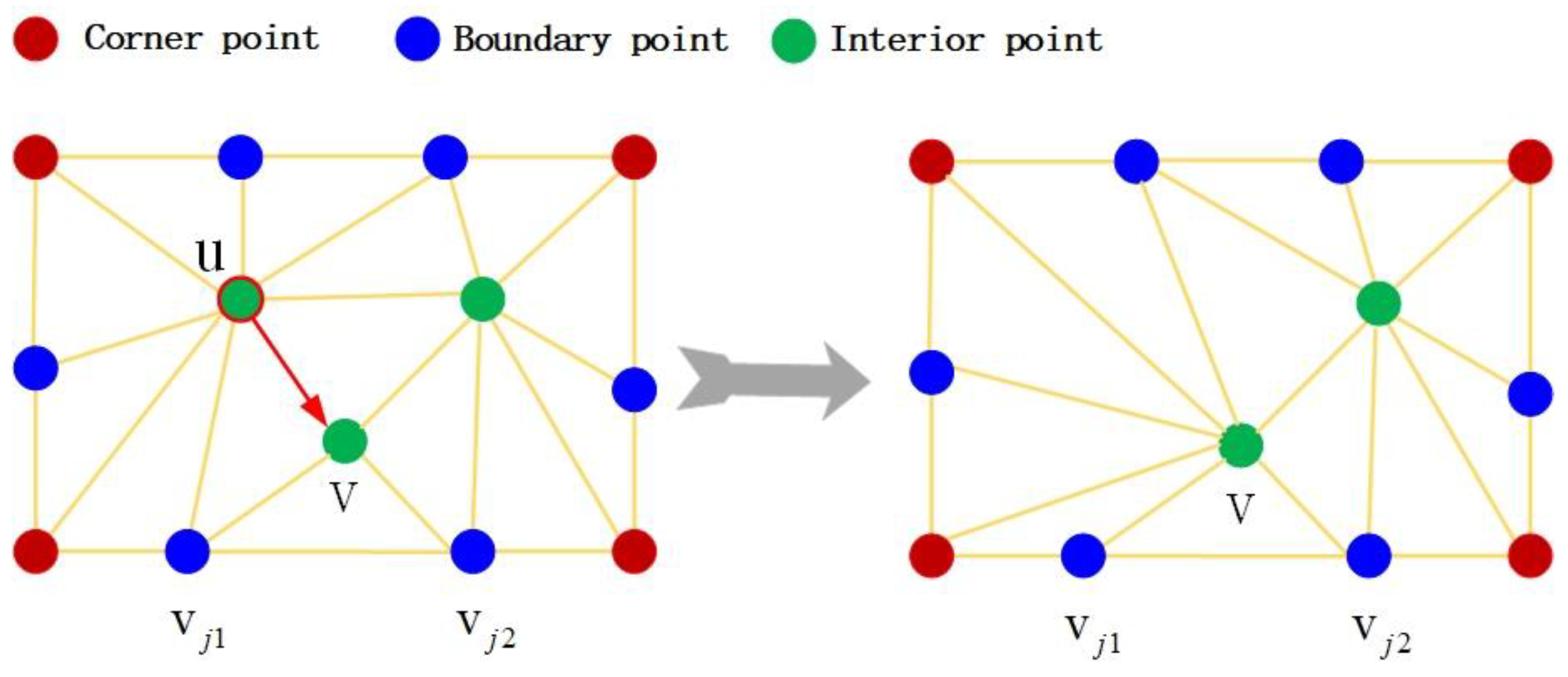
In this study, we chose the half-edge collapse method to simplify the model to avoid the extra data and computations caused by calculating the new vertex position during the collapse process. For each simplification of the half-edge collapse algorithm, a directed edge and a related pair of vertices u , v were selected by the algorithm; additionally, the vertex u was collapsed to the position of the v -point. All u -related vertices were replaced by the v -point, as shown in Figure 5.
The core of the half-edge folding method is the selection of folding edges, which determines the quality of the simplified model. The priority of edge collapse is mainly determined by calculating the error between the simplified model and original model after edge collapse, i.e., the collapse cost. When half-edge collapse occurs, the cost value of the edge to be collapsed corresponding to each point is calculated first, and then sorted according to the size of the cost value. The more the cost value is, the less influence it has on the entire mesh. Therefore, the edge is collapsed at the point with the lowest cost value to obtain the optimal simplified model.
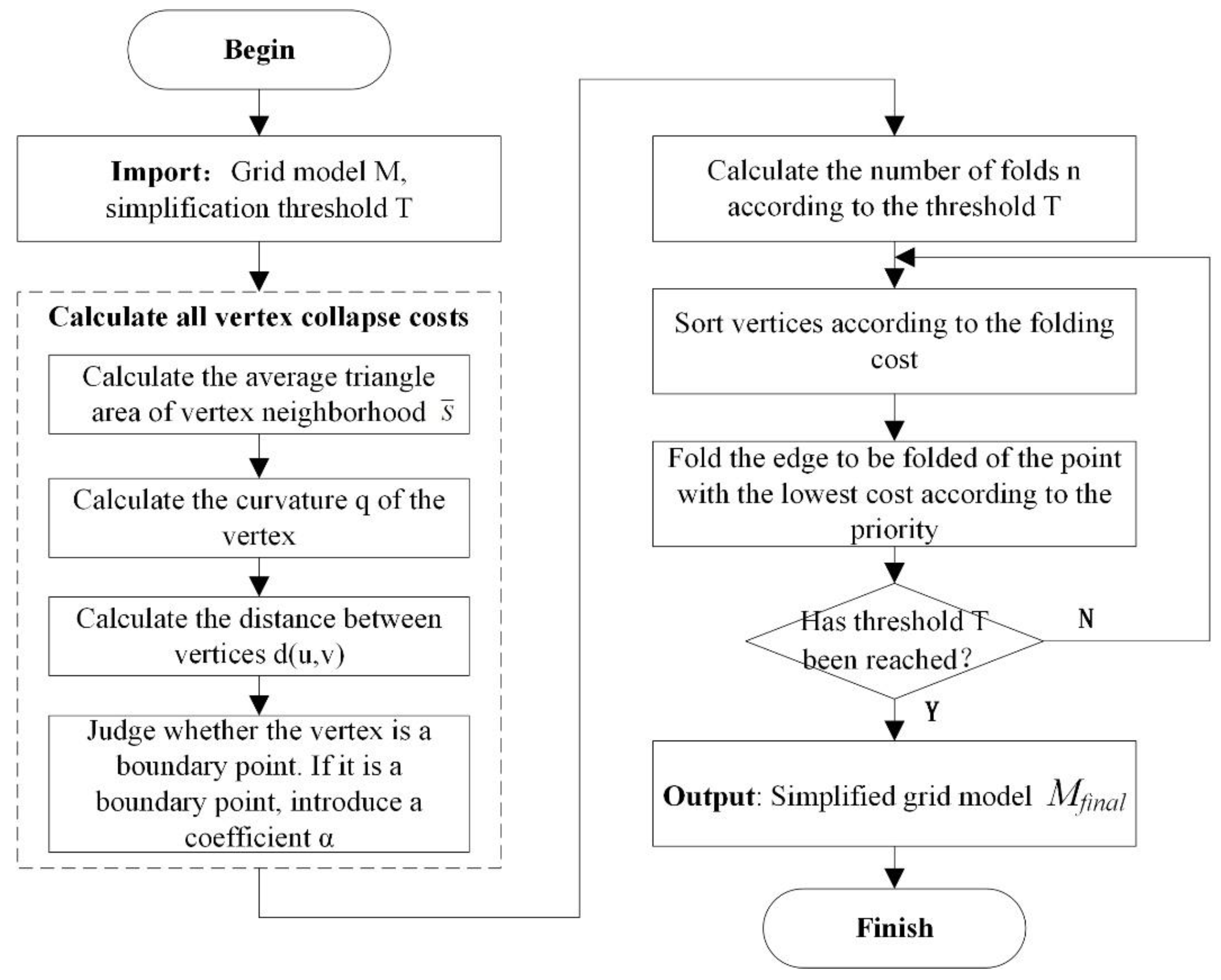
Based on the above analysis, an edge-based collapse cost calculation method was chosen. Considering the average area, curvature and distance of the triangle in the vertex neighborhood of the mesh, the boundary point factor was introduced to ensure the overall structure of the mesh model and simplify the 3D mesh model. The specific steps of the process are described in Figure 6.
The steps of the folding cost calculation method for the above mesh simplification process are described as follows.
  • Calculation of the average area of a vertex neighborhood triangle S ¯
To preserve the detailed features of a 3D mesh model, more triangular patches are often used to record the corresponding area. For this reason, the average area of the domain triangle of a vertex reflects, to some extent, the significance of the model characteristics at that vertex. The smaller the average area of triangles in the vertex domain, the more concentrated the density of triangular meshes and the more significant the model characteristics in the area will be. The larger the average area of the triangle in the vertex domain, the thinner the density of the triangle meshes and the less significant the model characteristics in this area will be. In the process of mesh simplification, feature areas should be avoided as much as possible. The average area of a vertex neighborhood triangle is given as follows:
S i ¯ = j = 1 n S i j n .
In the above formula, n denotes the number of neighborhood triangles of vertex i , and S i j denotes the area of the j th neighborhood triangle of vertex i .
2.
Calculation of the discrete curvature Q of vertices
The mesh simplification algorithm needs to minimize the number of triangular meshes in flat areas of the mesh, with an emphasis on preserving the triangular meshes in areas with sensitive geometric characteristics. Usually, the curvature of areas with obscure geometric features is smaller, and the curvature of areas with obvious geometric features is larger. For this reason, the discrete curvature feature was introduced to represent the degree of curvature of vertices in different directions [17]. If any vertex v on a mesh surface and its ring neighborhood vertex v j were recorded, the curvature of the vertex in the direction v , v j is then expressed as follows:
Q = 2 n v , v j v v j v 2 ,
In the above formula, n v represents the unit normal vector of vertex v , which is calculated by weighting the area of the neighborhood grid normal vector.
3.
Determination of a boundary point
Boundary point filtering is an important part of mesh simplification. Boundary points determine the geometric characteristics of the mesh. For this reason, when half-edge folding is performed, special attention should be paid to the preservation of boundary points. At present, half-edge folding is prone to structural changes and fracture in the boundary part of the model. For incompletely closed models, it is prone to the collapse of boundary points, which leads to the expansion of unclosed areas. The boundary point factor α ( α is a constant greater than 1) was introduced for this purpose.
The main basis for determining whether a collapse point is a boundary point is whether the number of adjacent triangles and edges of the point are equal; if they are equal, they are interior points, and vice versa. As shown in Figure 5, when the number of point v j 1 adjacent triangles is 3, the number of adjacent edges is 4; the number of adjacent triangles is not equal to the number of adjacent edges, and therefore, v j 1 is a boundary point v . The number of adjacent triangles for point v is 4, the number of adjacent edges is 4, and the number of adjacent triangles is equal to the number of adjacent edges; thus, v is an interior point. The boundary points should be kept as stable as possible in the simplification of the grid model so that the overall structure of the model remains unchanged.
4.
Calculation of distance between vertices  d u , v
The three aforementioned criteria ensure that the geometric features of the mesh model are obvious areas, while deleting the non-feature areas that will ultimately lead to the extreme phenomenon that feature areas are too concentrated in the simplified mesh. Therefore, the length of edges to be collapsed should also be taken into account in the process of mesh simplification. When the length of an edge in the grid is larger, a collapse of the edge will cause a larger overall grid change. Thus, in the process of model simplification, edges with smaller edge lengths should be folded first. The expression for folding edges is given as follows:
d u , v = u v ,
where ‖ ‖ represents the Euclidean distance between two points.
5.
Fold cost calculation
By combining the above four points, the folding cost of edges can be calculated as follows:
cos t u , v = α × d u , v × Q S ¯ i .

3.2.2. Mesh Distortion Optimization Algorithm

  • Laplacian mesh distortion
Within the framework of Laplacian mesh processing, by applying Laplacian operators to the vertices of discrete mesh models, we obtained a differential representation called Laplacian coordinates. In comparison with Cartesian coordinates, which directly define the spatial location information of each vertex, surface-based differential expressions can describe local information, including size and direction; thus, the algorithm that tries to keep Laplace coordinates unchanged maintains local details of the surface as much as possible during processing.
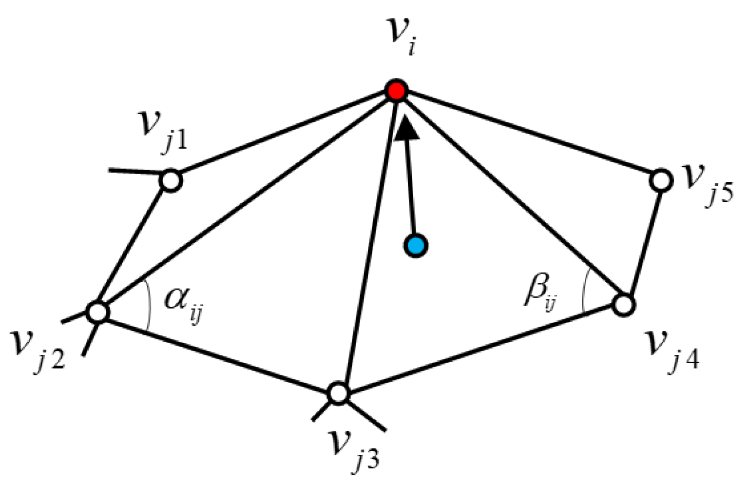
Generally, M = V , E , F represents a 3D surface model, V represents the vertex set in the model, E is the edge set, and F is the triangle set. As shown in Figure 7, the initial coordinate of the vertex in the model is the absolute coordinate v i = x i , y i , z i in the Cartesian coordinate system, which defines the Laplace coordinate δ i of the vertex expressed as
δ i = δ i x , δ i y , δ i z = v i j N i ω i j v j ,
where N ( i ) = j i , j E represents all vertices that can form an edge with vertex v i , i.e., neighborhood vertices; ω i j is vertex v j relative to v i and ω i j = 1 . For calculating the weights ω i j , we selected the cotangent weight equation as
ω i j = 1 2 cot α i j + cot β i j ,
where α i j and β i j are diagonals of two adjacent triangular facets of edge v i v j , as shown in Figure 7. Cotangent weights can reflect curvature information of a surface and, to some extent, local geometric information of points. Here, we used cotangent weights to calculate the mesh distortion, and the differential coordinates were expressed as approximations of the average normal curvature, as follows:
δ i = v i 1 2 j N i   cot α i j + cot β i j v j ,
2.
Laplacian matrix
L was introduced as a Laplacian matrix to convert the absolute coordinates into relative coordinates as
Δ = δ i T = L n * n V n * 3 = I D 1 A V n * 3 ,
where Δ is a Laplacian coordinate, and D is a diagonal matrix ( D i i = d i ).  A is the adjacency matrix of the grid, where
A i j = 1 ( i , j ) E 0 o t h e r w i s e ,
Furthermore, L is an n × n matrix whose components are in the following form:
L i j = 1 , i = j ω i j 0 , o t h e r , j N i ,
3.
Addition of constraints
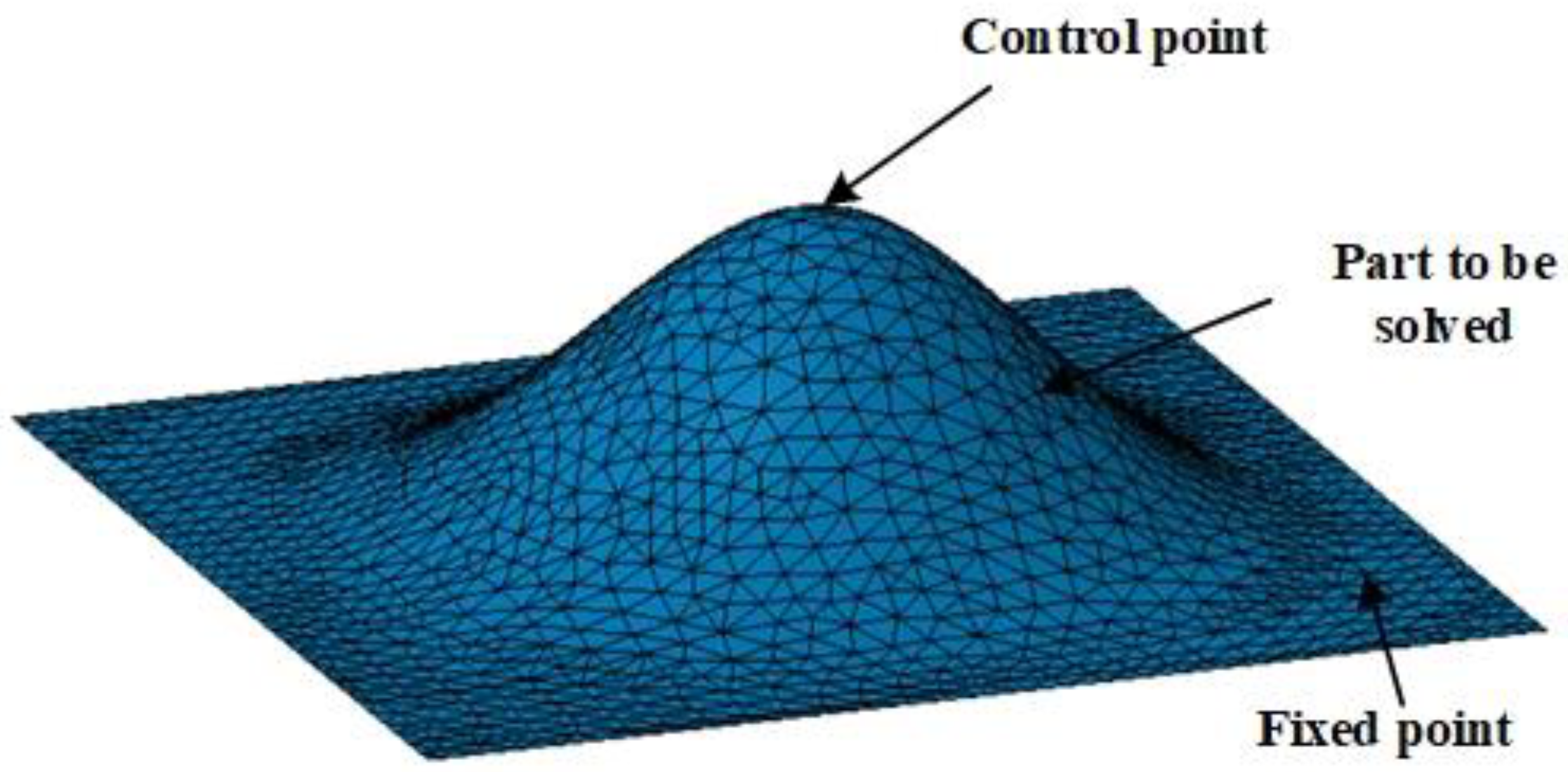
As shown in Figure 8, the model mesh deformation was divided into three parts: the fixed part, the part to be solved and the known control point part. The essence of Laplacian deformation is to solve the coordinates of the part to be solved according to the fixed part and the known control point coordinates by modifying the control point coordinates.
The sum of elements in each row of the Laplacian operator matrix L is 0, which must be a singular matrix that is not a full rank matrix, i.e., L is irreversible. Therefore, there is no unique and definite solution to solve the Cartesian coordinates of the grid model with matrix L . Hence, at least one constraint point was introduced to make the solution object unique. In practice, multiple constraint conditions were generally set, and the absolute coordinates of the deformed mesh vertices were obtained by solving the matrix with the least squares method.
4.
Establishment of deformation constraints
After the deformation of the surface, the new position w i of the control point was measured. It was necessary to move the corresponding point of the source model to the new position after the deformation under the condition that the relative position of each vertex remained unchanged. It was expressed by  v i , and v i = w i , i = 1 , 2 , 3 , , m was satisfied. Based on the mesh deformation of Laplacian coordinates, the solution of the deformed vertex V was summed up as an optimization problem with position constraints as follows:
V = argmin V ( L V Δ 2 + i = 1 m ω 2 v i w i 2 ) ,
where ω is the weight value of the constraint point. L V Δ ensured that the coordinates of the model remained unchanged as much as possible after deformation; v i w i ensured that the constraint points could reach the target position. The minimum problem in the solution was equivalent to solving the following statically indeterminate linear system (the number of equations was greater than the number of unknowns):
A V = L H V = Δ h = b ,
where H is a m × n order matrix, and the H value is the weight value of the corresponding constraint point pair. h is an m × 3 matrix, i.e., h i = ω i w i , i = 1 , 2 , 3 , , m ; each column represents a coordinate component. The unknown number V is the n × 3 matrix, and its i line represents the 3D coordinate v i ( x , y , z ) of the deformed mesh vertex. To solve the linear system, only the following equation was needed:
A V = b ,
The 3D coordinates of each vertex after deformation were obtained by the following equation:
V = ( A T A ) 1 · A T b .
when the mesh model was deformed, the vertex coordinates of the new model were obtained by updating the b matrix.

3.2.3. Pseudocode

In this paper, the half-edge folding method was introduced to optimize the Laplacian mesh deformation algorithm, and a mesh deformation algorithm based on point-cloud optimization was constructed. The pseudocode is shown in Algorithm 1:
  Algorithm 1.  Pseudocode for HEC-Laplace
  1:  Input: Original grid control points before and after deformation simplification threshold
  2:  Output: Deformed grid runtime
  3:   Initialization:
  4:         Compute folding times based on simplification threshold
  5:   Model simplification:               (Section 3.2.1)
  6:         Compute folding cost by Equation (15);
  7:      Sort vertices according to collapse cost;
  8:      Folding edges with the least cost by priority;
  9:   Grid Deformation:             (Section 3.2.2)
10:         Verify the set of one-ring neighborhood points for each vertex;
11:         According to Equation (16) define the Laplace coordinates of the vertices;
12:         According to Equation (17) compute cotangent weights;
13:         Introduce a Laplacian matrix based on Equation (19) convert Cartesian coordinates to differential coordinates;
14:         According to Equation (23) establishment of statically indeterminate systems of linear equations;
15:         Solve equations to obtain the new position of the vertex under the Cartesian coordinate system.

4. Results and Discussion

To evaluate the accuracy and effectiveness of the technical scheme proposed in this paper, simulation and model experiments were carried out. In Section 4.1, the unequal curvature model is designed, and the stress simulation deformation of this model is carried out to verify the deformation accuracy of the model deformation algorithm. In Section 4.2, the deformation effect of a cantilever wing is tested under different loads to evaluate the feasibility of the technical scheme.

4.1. Comparison of Deformation Algorithm through Simulations

4.1.1. Model Evaluation

To evaluate the deformation accuracy of the model quantitatively, relevant indicators were used for evaluation and analysis. Among them, the mean absolute error (MAE), relative error (RE) and root mean square error (RMSE) were used to quantitatively evaluate the deformation accuracy of the model expressed as follows:
M A E = 1 n i = 1 n y ^ i y i ,
R E = i = 1 n y ^ i y i y i × 100 % ,
R M S E = 1 n i = 1 n y ^ i y i 2 ,
where n is the predicted quantity, y i is the true value, and y ^ i is the predicted value.

4.1.2. Simulation Experiments

A deformation model is key to realizing 3D mapping technology. For this reason, we verified the effectiveness and accuracy of the HEC-Laplace algorithm, and compared it with the interpolation [18], Gaussian fusion [19], and Laplace algorithms [20]. Among them, the interpolation algorithm is the traditional reconstruction method of a current sensor detection methodology.
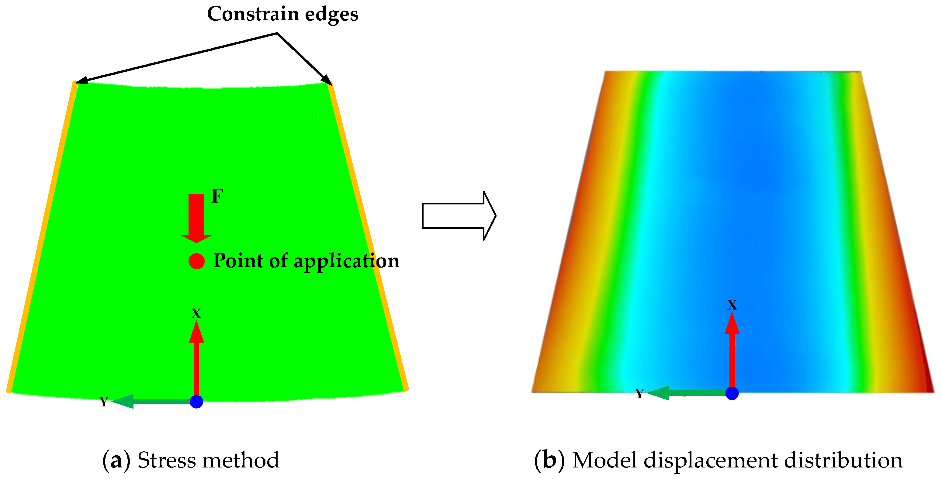
In order to verify the deformation effect of the deformation algorithm in this paper, the deformation effect was verified by a 3D surface with unequal curvature of 400 mm × 300 mm (in length and width). As shown in Figure 9, the unequal curvature model was placed horizontally, and its two long edges were constrained in the Z direction, so that it can only move in the X and Y directions. At the same time, the unequal curvature model was subjected to a unilateral local load of 50 N, and the stress direction and position are shown in Figure 9a. The displacement distribution results of the model after stress were shown in Figure 9b, where the blue area was the inward contraction of the deformed model relative to the original model at its normal position, and the red area was the outward expansion of the deformed model relative to the original model at its normal position. The number of triangles of the original surface was 773,465, and the number of vertices was 387,517. Thirty points were uniformly selected as control points on the deformed surface to verify the accuracy of the deformation algorithm.
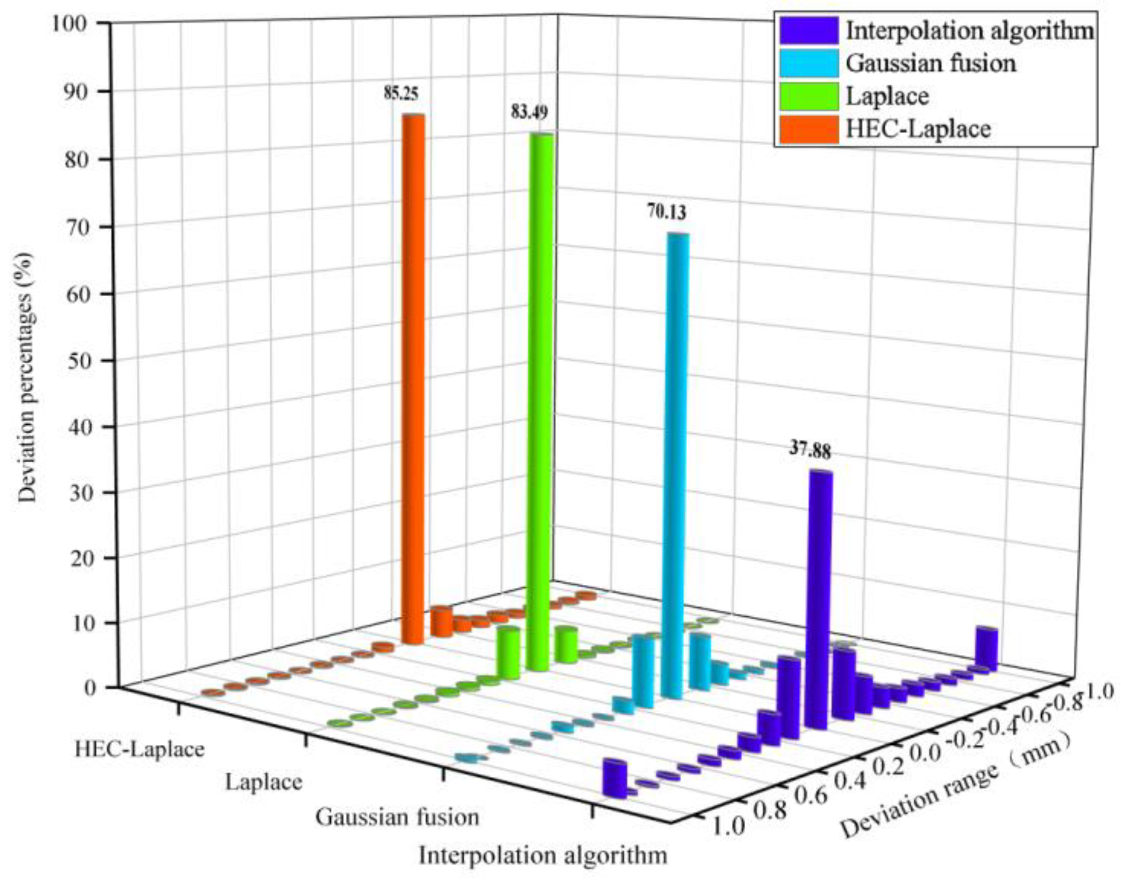
To verify the accuracy of the HEC−Laplace algorithm, based on the original surface and deformed control points, 3D deformation mapping of the above surface was carried out by the interpolation, Gaussian fusion, Laplace, and optimized Laplace algorithms. The deviation consistency between the mapped and actual deformed surfaces was detected, and the deformation accuracy after the mapping of the above four algorithms was analyzed, as shown in Figure 10. Here, Figure 10a shows the consistency detection result of the interpolation algorithm, 10b shows the consistency detection result of the Gaussian fusion algorithm, 10c shows the consistency detection result of the Laplace algorithm, and 10d shows the consistency detection result of the optimized Laplace algorithm. Furthermore, the right-hand side of the figure shows the deviation chromatogram of the histogram. To make the result clearer, we set the red range, as the mapping surface was higher than the actual deformation surface in the normal direction. The blue range shows that the mapping surface was lower than the actual deformation surface in the normal direction, and the green part shows that the deviation range was within the range of [−0.1, 0.1]. It can be clearly seen from the figure that the Laplace algorithm is significantly superior to the interpolation and Gaussian-fusion algorithms. To further analyze the accuracy of the deformation algorithm, the consistency results of the above four algorithms were statistically analyzed for the percentage of deviation. The results are shown in Figure 11. It can be seen from the figure that within the range of [−0.1, 0.1], the percentage of point clouds of the interpolation algorithm is 37.88%, the percentage of point clouds of the Gaussian fusion algorithm is 70.13%, the percentage of point clouds of the Laplace algorithm is 83.49%, and the percentage of point clouds of the HEC-Laplace algorithm is 85.25%.
To assess the distortion accuracy of the model further quantitatively, the indexes described in Section 4.1.1 were used for evaluation and analysis. We selected 45 deformation-monitoring points on the surface of the model, obtained their actual and simulated displacements under the interpolation, Gaussian fusion, Laplace and HEC−Laplace algorithms, and calculated the overall index of all deformation monitoring point data. Simultaneously, to evaluate the deformation efficiency of the HEC−Laplace algorithm, the deformation time of the unequal curvature model was calculated. The results are presented in Table 1.
As presented in Table 1, the first three columns of the evaluation metrics are the error values under different deformation algorithms. Except for the interpolation algorithm, the other three algorithms have high deformation accuracy. Among them, HEC−Laplace has obvious advantages, i.e., its MAE value is 0.046, RE value is 2.92%, and RMSE value is 0.062. In terms of deformation efficiency, in addition to interpolation algorithm, HEC-Laplace runs for 42.47 s, and its deformation efficiency is higher than Gaussian fusion and Laplace algorithms. In summary, the HEC−Laplace model reflects the best deformation effect, and further validates the advantages of the proposed 3D mapping algorithm for structural deformation.

4.2. Application of Structural Deformation Mapping

4.2.1. Establishment of Experimental System

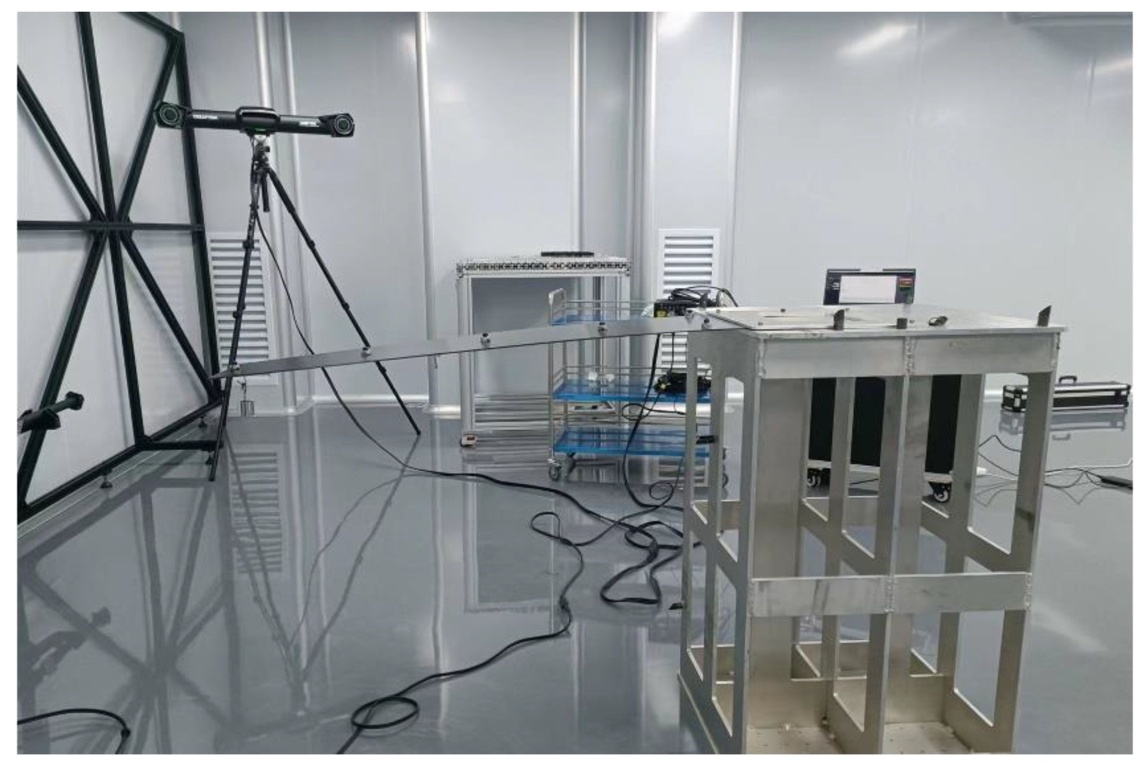
To evaluate the feasibility of 3D mapping technology of structural deformation in this study, the aircraft wing was simplified to a single-sided fixed support carbon-fiber-reinforced polymer (CFRP) composite laminate. Different load forces were applied to different positions of the CFRP laminate, and the deformation of the wing model under different loads was analyzed. The wing model was made of T300 3 K (TORAY company) high-strength carbon cloth, formed by cross-ply hot-pressing process, and had the characteristics of lightweight, high strength, and good stability. The overall components of the experimental system mainly included the carbon fiber simplified wing, fixed platform (with fixed support to fix the wing on one side), binocular vision system, fiber grating demodulator, different counterweight weights, and workstations, as shown in Figure 12. In the experiment, the size of the wing model was 1100 mm × 300 mm, and the thickness was 3 mm; additionally, the installation method of single sided fixing was adopted.
After the wing model was fixed, we first obtained the point-cloud data of the wing’s 3D shape without loading through the binocular vision scanning system, and established a high-fidelity model with high accuracy and integrity. The binocular vision scanning system used the Creamform factory tracking scanner, which was composed of C-Track optical tracker and optical CMM 3D scanner, with a scanning accuracy of 0.064 mm (9.1 m3) and a resolution of 0.05mm. The binocular vision scanning system was based on the binocular stereo vision measurement principle and the structured light 3D vision measurement principle to quickly obtain the high-density point cloud data of the product. The results are shown in Figure 13; the number of triangular patches in the scanning data was 868,286, and the number of vertices was 434,152, which provides true and reliable data for subsequent 3D mesh deformation.
The quasi-distributed FBG sensor network was pasted on the wing model; this project used the Optical System 256 fiber grating demodulation system of Beijing Xizhuo Information Technology Co., Ltd. (Beijing, China), which integrated several modules such as light source, data acquisition, network communication, etc. The wavelength range was 1528 nm~1568 nm, the wavelength resolution is 0.1 pm, and the synchronous frequency is 100 Hz. At the same time, it was equipped with four measurement channels. The sensor network was constructed using wavelength division multiplexing and space division multiplexing technology, and the wavelength division technology was used in each channel to realize the grating wavelength demodulation of a single channel. Each channel was distributed with a number of FBG sensors with different central wavelengths, which were distributed in series at different locations according to the wavelength division multiplexing technology. The space division multiplexing technology was used to realize the multiplexing of each channel. In this paper, 12-grid grating array was used for single-channel demodulation. The initial center wavelength of FBG sensor was increased from 1531 nm to 1564 nm, and the initial center wavelength difference between two adjacent gratings was set to 3 nm to avoid interference of different grating wavelengths.
The optical fiber distribution of the wing model is shown in Figure 14. The sensor network consisted of 34 fiber-grating strain sensors; each of them is a pair that is arranged orthogonally to generate 17 measurement nodes. In the figure, the red sensor is the X-direction strain monitoring point, and the blue sensor is the Y-direction strain monitoring point. Among them, points A, B, and C are the force application points, which are located at different positions of the wing tip. We also verified the deformation of the wing model under different loads. The results of five different load application methods are presented in Table 2.
For the entire system, the quasi-distributed FBG sensor network and the carbon fiber wing model were integrated into an intelligent sensor structure to monitor the deformation state of the flexible single-sided fixed support plate structure in real time. Using the derivation method presented in Section 3.1, the center wavelength offset obtained from optical fiber monitoring was collected in real time, and the 3D offset of the monitoring point space was obtained through orthogonal discrete curvature information and the coordinate derivation algorithm. The binocular vision measurement system was used to measure the shape of the model after each deformation. We obtained the corresponding true displacement values of each point of the single-sided fixed carbon fiber board, and used them to compare with the structural deformation mapping results, to ensure the accuracy of the 3D mapping scheme of the single-sided fixed carbon fiber board and effectiveness of the experimental data analysis [21].

4.2.2. Experimental Results

According to the above experimental process, the optical fiber center wavelength drift Δ λ B of 34 FBG sensors at 17 measuring points on the wing surface under different loading conditions and the 3D point cloud data of the wing model under the unloaded condition were obtained. According to the theoretical derivation in Section 3, the deformed wing was reconstructed under different conditions, and the deformed wing model data were obtained to verify the reconstruction effect, the deviation consistency was checked with the wing model data obtained from binocular vision measurement under different loading conditions.
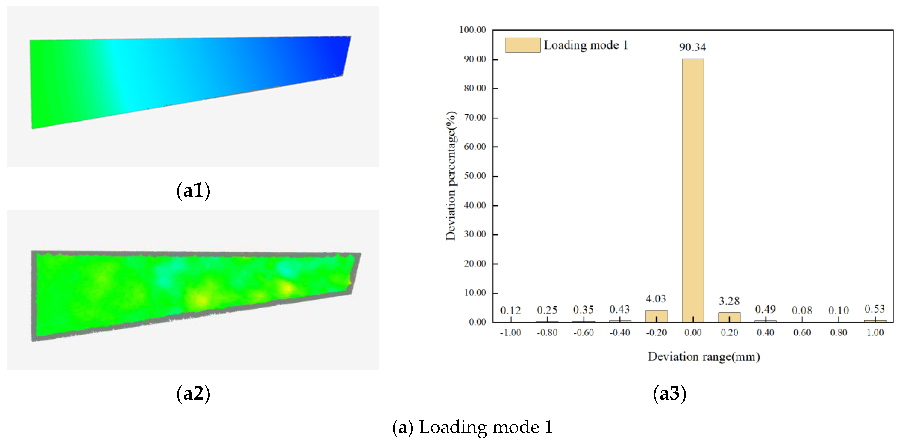
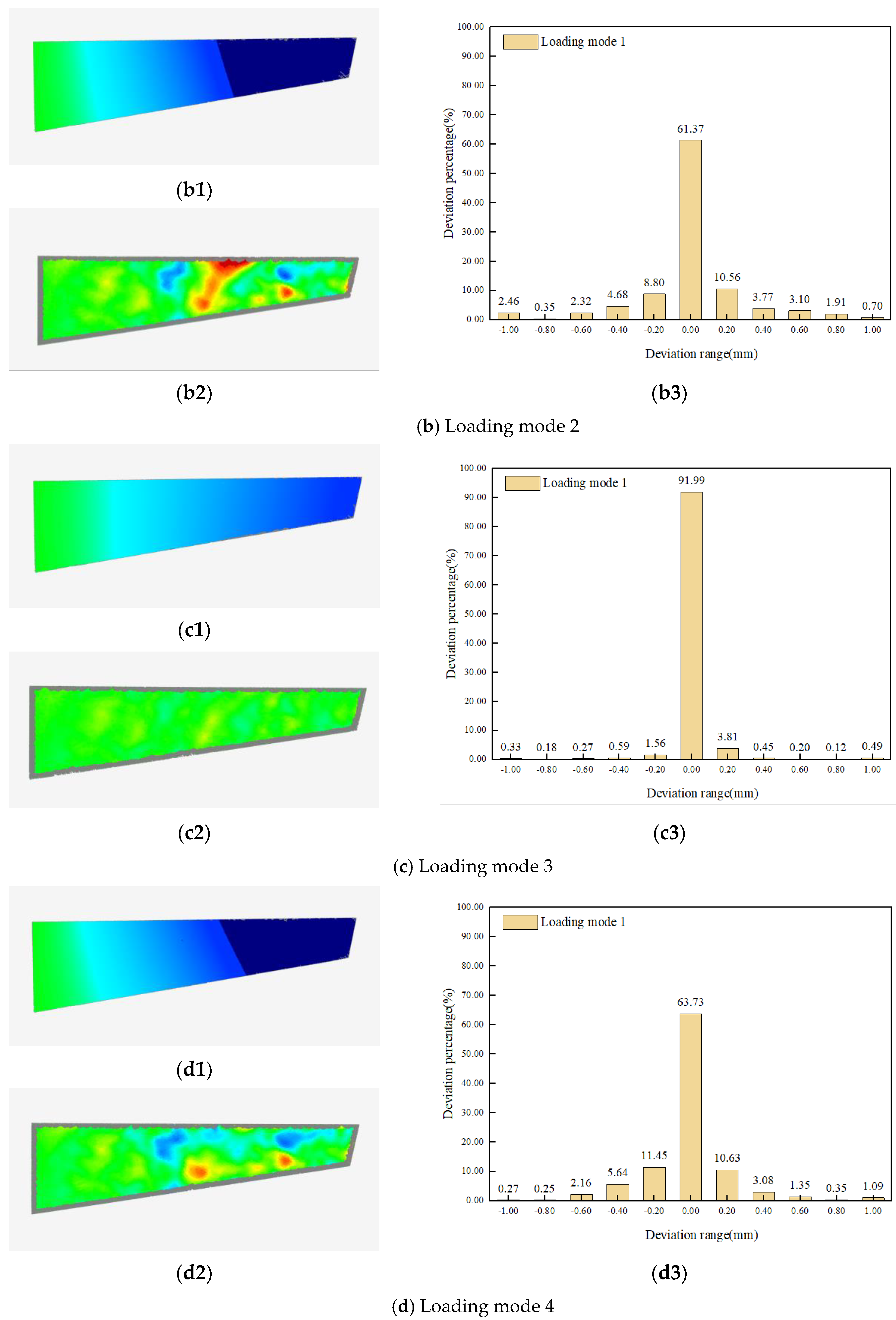
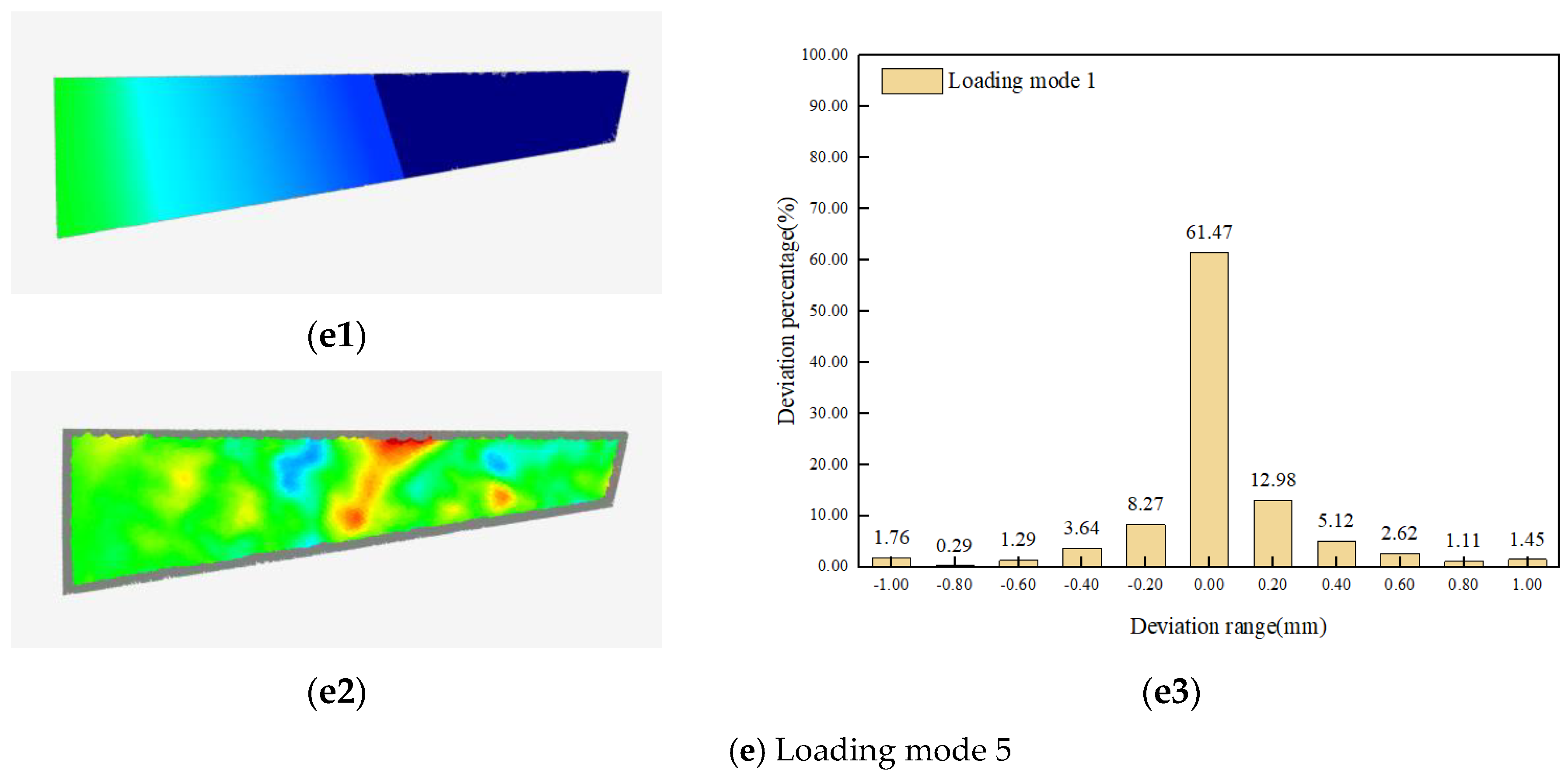
The shape variables of the wing, the amount of deviation between the reconstructed and actual models, and the percentage of deviation distribution at each deformation under the above five loading conditions are shown in Figure 15. Among them, Figure 15(a1–e1) shows the results of the shape variables of the wing model under the above five loading modes, Figure 15(a2–e2) shows the results of the deviation consistency test between the reconstructed model and the actual wing point cloud data measured by binocular under the above five loading modes, and Figure 15(a3–e3) shows the percentage of the deviation result point cloud distribution under the above five loading modes.
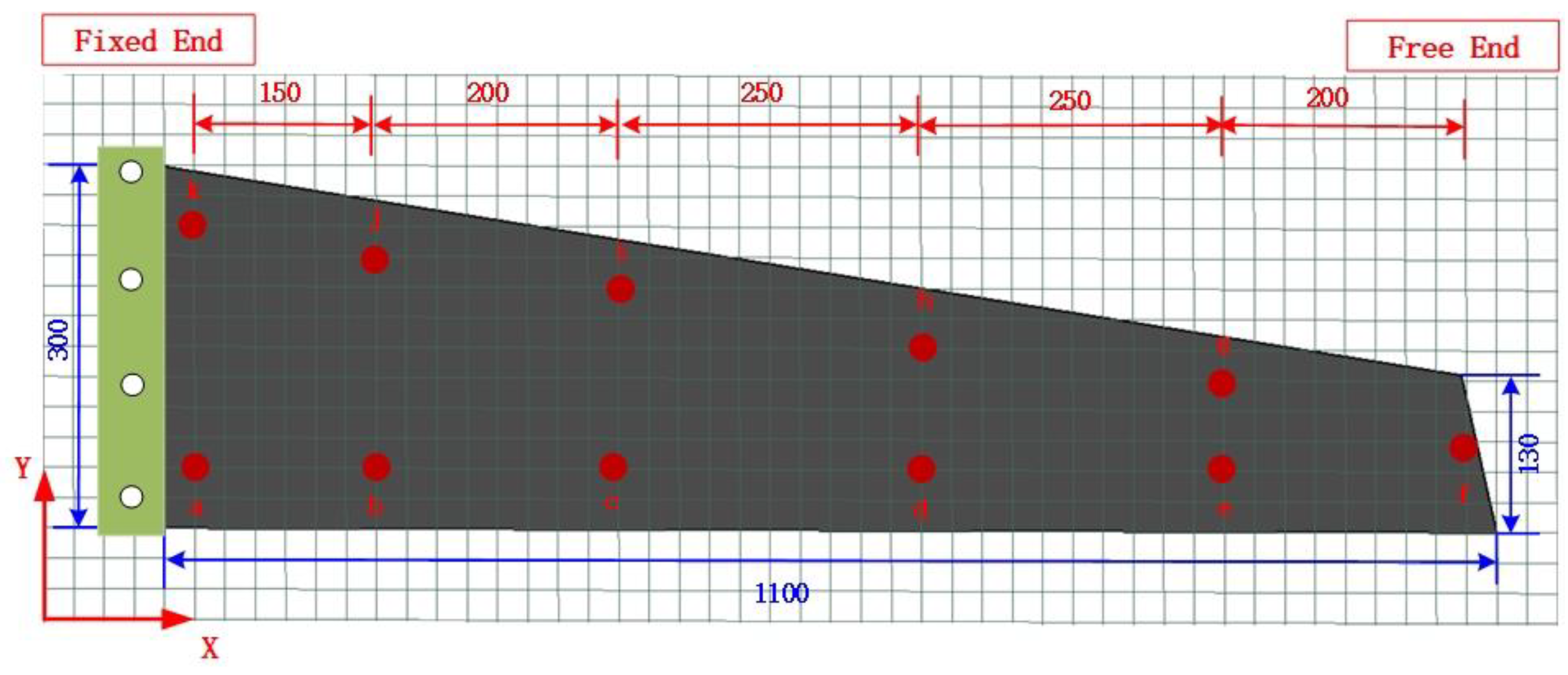
To describe the deformation accuracy of the model further, 11 points were selected on the wing as the inspection points of the deformation effect, as shown in Figure 16 (a–k points). Simultaneously, the wing deformation reconstruction results were evaluated and analyzed using the relevant metrics described in Section 4.1.1; the results are presented in Table 3.
Based on the above experimental results, it is evident that the proposed method can obtain model deformation data accurately and efficiently, and its reconstruction effect is consistent with the actual deformation effect. As observed from Figure 15 and Table 3, when the maximum unilateral distortion was within the range of 30 mm, more than 90% of the point-cloud deviation was within the range of [−0.1, 0.1]. Among them, load mode 3 had the highest reconstruction accuracy, with an MAE of 0.094, RE of 2.62%, and RMSE of 0.111. The evaluation model results of load mode 1, similar to those of loading mode 3, exhibited the same magnitude. Simultaneously, it can be observed that the accuracy of reconstruction decreases with an increasing amount of deformation. These results indicate that a new model can be acquired accurately and efficiently by using the proposed 3D mapping technology for structural deformation during the assembly process of aircrafts.

5. Conclusions

A 3D mapping technique was proposed for evaluating the structural deformation during aircraft assembly processes. First, 3D point-cloud data of the aircraft surface structure were obtained based on a binocular vision system. Second, the waveform data of optical fiber monitoring of the aircraft under different assembly states were obtained based on a quasi-distributed optical fiber sensor, and the relationship between waveform information of optical fiber monitoring of the aircraft and distortion was deduced by using the tangent recurrence method to complete the heterogeneous data integration. Third, the Laplacian mesh distortion algorithm was optimized by introducing the half-edge folding method, and a mesh-distortion algorithm based on point-cloud optimization (HEC-Laplace) was constructed. In addition, the feasibility and accuracy of HEC-Laplace were verified by comparing the unequal curvature surface distortion through interpolation, Gaussian-fusion, and Laplacian algorithms. Finally, the proposed technique was validated based on a simple model of aircraft wings. The results show that when the distortion was less than 30 mm, more than 90% of the deviations of 3D point clouds were within the deviation range of [−0.1, 0.1]; the average absolute error was 0.094 mm, the relative error was 2.62%, and the root mean square error was 0.111 mm. A 3D mapping of the aircraft-wing structural distortion was implemented to improve accuracy control and the overall assembly quality during the aircraft assembly. In the future, the optical fiber layout of complex structures will be explored to better solve the 3D mapping technology of structural distortion during assembly.

Author Contributions

Conceptualization, Y.L. and X.L.; methodology, Y.L. and L.G.; software, Y.L. and D.Y.; validation, Y.L.; formal analysis, Y.L.; investigation, Y.L.; resources, Y.L.; data curation, Y.L.; writing—original draft preparation, Y.L.; writing—review and editing, Y.L.; visualization, Y.L.; supervision, L.L., X.L. and L.G.; project administration, Y.L. and X.L.; funding acquisition, L.L., X.L. and L.G. All authors have read and agreed to the published version of the manuscript.

Funding

This research was funded by the Key Research and Development Project of the Jilin Province Science and Technology Development Program (No. 20200401019GX) and the Zhongshan Social Public Welfare Science and Technology Research Project (No. 2022B2013).

Institutional Review Board Statement

Not applicable.

Informed Consent Statement

Not applicable.

Data Availability Statement

The data presented in this study are available on request from the corresponding author.

Conflicts of Interest

The authors declare no conflict of interest.

References

  1. Zhao, Z.; Gan, X.; Liqun, M.A. A Combined Adjustment Network Method Based on Multi-Sensor System Cooperative Measurement. Chin. J. Sens. Actuators 2019, 32, 100–105. [Google Scholar]
  2. Zhang, Y.; Shen, Y.; Zhang, W.; Zhang, L.; Zhu, L.; Zhang, Y. Generation of efficient and interference-free scanning path for inspecting impeller on a cylindrical CMM. Measurement 2022, 198, 111352. [Google Scholar] [CrossRef]
  3. Chen, Z.; Zhang, F.; Qu, X.; Liang, B. Fast Measurement and Reconstruction of Large Workpieces with Freeform Surfaces by Combining Local Scanning and Global Position Data. Sensors 2015, 15, 14328–14344. [Google Scholar] [CrossRef] [PubMed] [Green Version]
  4. Ser’Eznov, A.N.; Stepanova, L.N.; Laznenko, A.S.; Kabanov, S.I.; Kozhemyakin, V.L.; Chernova, V.V. Static Tests of Wing Box of Composite Aircraft Wing Using Acoustic Emission and Strain Gaging. Russ. J. Nondestruct. Test. 2020, 56, 611–619. [Google Scholar] [CrossRef]
  5. Wang, Q.; Dou, Y.; Li, J.; Ke, Y.; Keogh, P.; Maropoulos, P.G. An assembly gap control method based on posture alignment of wing panels in aircraft assembly. Assem. Autom. 2017, 37, 422–433. [Google Scholar] [CrossRef] [Green Version]
  6. Zhang, W. Research on Digital Preassembly Technology of Aircraft Parts Based on Measured Data; Nanjing University of Aeronautics and Astronautics: Nanjing, China, 2016. [Google Scholar]
  7. Guo, F.; Liu, J.; Zou, F.; Zhai, Y.; Wang, Z.; Li, S. Research on assembly process design and key implementation technology of digital twin drive. Chin. J. Mech. Eng. 2019, 55, 110–132. [Google Scholar]
  8. Sun, G.; Wu, Y.; Li, H.; Zhu, L. 3D shape sensing of flexible morphing wing using fiber Bragg grating sensing method. Optik 2018, 156, 83–92. [Google Scholar] [CrossRef]
  9. Ma, Z.; Chen, X. Strain transfer characteristics of surface-attached FBGs in aircraft wing distributed deformation measurement. Optik 2020, 207, 164468. [Google Scholar] [CrossRef]
  10. Wang, B.; Fan, S.; Chen, Y.; Zheng, L.; Zhu, H.; Fang, Z.; Zhang, M. The replacement of dysfunctional sensors based on the digital twin method during the cutter suction dredger construction process measurement. Measurement 2022, 189, 110523. [Google Scholar] [CrossRef]
  11. Zhang, S.; Yan, J.; Jiang, M.; Sui, Q.; Zhang, L.; Luo, Y. Visual reconstruction of flexible structure based on fiber grating sensor array and extreme learning machine algorithm. Optoelectron. Lett. 2022, 18, 390–397. [Google Scholar] [CrossRef]
  12. Brindisi, A.; Vendittozzi, C.; Travascio, L.; Di Palma, L.; Ignarra, M.; Fiorillo, V.; Concilio, A. A Preliminary Assessment of an FBG-Based Hard Landing Monitoring System. Photonics 2021, 8, 450. [Google Scholar] [CrossRef]
  13. Ding, G.; Wang, F.; Gao, X.; Jiang, S. Research on Deformation Reconstruction Based on Structural Curvature of CFRP Propeller with Fiber Bragg Grating Sensor Network. Photon- Sens. 2022, 12, 220412. [Google Scholar] [CrossRef]
  14. Yi, L.; Xue, Z.; Ding, Y.; Wang, M.; Guo, Z.; Shi, J. Surface Curvature Sensor Based on Intracavity Sensing of Fiber Ring Laser. Photonics 2022, 9, 781. [Google Scholar] [CrossRef]
  15. Alexa, M. Differential coordinates for local mesh morphing and deformation. Vis. Comput. 2003, 19, 105–114. [Google Scholar] [CrossRef]
  16. Jäckle, S.; Strehlow, J.; Heldmann, S. Shape sensing with fiber bragg grating sensors-a realistic model of curvature interpolation for shape reconstruction. In Bildverarbeitung für die Medizin; Springer: Wiesbaden, Germany, 2019; pp. 258–263. [Google Scholar]
  17. Taubin, G. Estimating the tensor of curvature of a surface from a polyhedral approximation. In Proceedings of the IEEE International Conference on Computer Vision, Cambridge, MA, USA, 20–23 June 1995. [Google Scholar]
  18. Hao, J.; Tang, L.; Zeng, P. A Simplification Algorithm for Curvature and Area-Weighted Quadric Error Metrics Mesh. J. Donghua Univ. 2012, 38, 318–322. [Google Scholar]
  19. Ding, J.; Liu, T.-Y.; Bai, L.; Sun, Z. A multisensor data fusion method based on gaussian process model for precision measurement of complex surfaces. Sensors 2020, 20, 278. [Google Scholar] [CrossRef] [PubMed] [Green Version]
  20. González-Gaxiola, O.; Biswas, A.; Moraru, L.; Moldovanu, S. Highly Dispersive Optical Solitons in Absence of Self-Phase Modulation by Laplace-Adomian Decomposition. Photonics 2023, 10, 114. [Google Scholar] [CrossRef]
  21. Wu, J.; Cai, X.; Wei, J.; Wang, C.; Zhou, Y.; Sun, K. A Measurement System with High Precision and Large Range for Structured Surface Metrology Based on Atomic Force Microscope. Photonics 2023, 10, 289. [Google Scholar] [CrossRef]
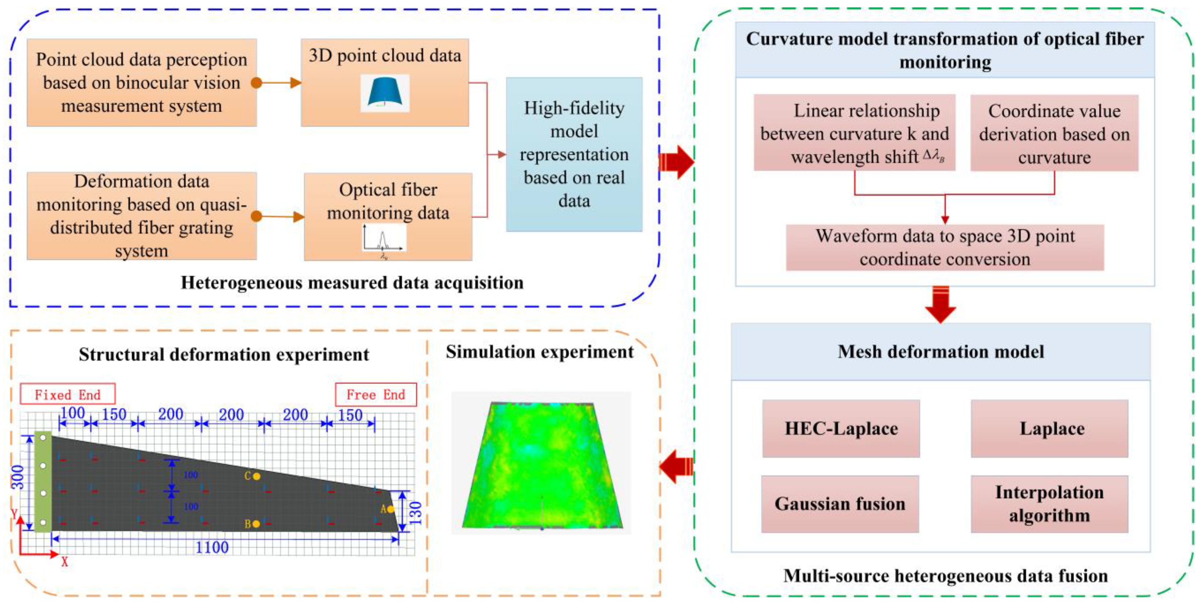
Figure 1. General scheme of multi-source heterogeneous data fusion for aircraft assembly process.
Photonics 10 00318 g001
Figure 2. FBG tension and compression model under pure bending.
Photonics 10 00318 g002
Figure 3. Surface deformation model under stress.
Photonics 10 00318 g003
Figure 4. Coordinate value derivation graph.
Photonics 10 00318 g004
Figure 5. Schematic of half-edge collapse optimization algorithm.
Photonics 10 00318 g005
Figure 6. Flowchart of the optimization algorithm for half-edge collapse.
Photonics 10 00318 g006
Figure 7. Differential coordinate diagram (local one ring domain).
Photonics 10 00318 g007
Figure 8. Schematic of model deformation.
Photonics 10 00318 g008
Figure 9. Stress diagram of the unequal curvature model.
Photonics 10 00318 g009
Figure 10. Comparison of deviation between the deformed mesh algorithm and actual deformed model: (a) Interpolation algorithm; (b) Gaussian fusion; (c) Laplace; and (d) HEC−Laplace.
Photonics 10 00318 g010
Figure 11. Schematic of the percentage of point−cloud deviation of the deformation algorithm.
Photonics 10 00318 g011
Figure 12. Photograph of the experimental system.
Photonics 10 00318 g012
Figure 13. 3D scanning data of the wing.
Photonics 10 00318 g013
Figure 14. Simplified wing geometry and optical fiber distribution (unit: mm).
Photonics 10 00318 g014
Figure 15. Wing deformation/reconstruction deviation diagrams or the deviation distribution diagrams under different loading modes. (a1e1) Results of wing model shape variables under five load modes; (a2e2) The deviation consistency test results between the reconstructed model and the binocular measured point cloud data under the five loading modes; (a3e3) Percentage of deviation result point cloud distribution under five loading modes.
Photonics 10 00318 g015aPhotonics 10 00318 g015bPhotonics 10 00318 g015c
Figure 16. Location distribution of the deformation-effect inspection points (unit: mm).
Photonics 10 00318 g016
Table 1. Deformation evaluation indexes of unequal curvature model.
ModelEvaluation Index
MAERERMSETime (s)
Interpolation algorithm 0.38819.77%0.60910.47
Gaussian fusion 0.0645.28%0.09050.54
Laplace 0.0583.47%0.075591.22
HEC−Laplace 0.0462.92%0.06242.47
Highlighted in bold means the best evaluation result of the deformation model.
Table 2. Load application mode.
Node NumberLoading ModeLoad SizeLoad Application Position
1 Single point 2 NPoint A
2 Single point 5 NPoint A
3 Single point5 NPoint B
4 Multipoint loading2 N
5 N
Point A
Point C
5 Multipoint loading2 × 5 NPoints B and C
Table 3. Evaluation of wing deformation results.
Node NumberMaximum Deformation (mm)Evaluation Index
MAERERMSE
129.940.1043.78%0.146
273.680.2103.02%0.307
328.060.0942.62%0.111
464.030.2002.82%0.272
563.700.2473.50%0.325
Disclaimer/Publisher’s Note: The statements, opinions and data contained in all publications are solely those of the individual author(s) and contributor(s) and not of MDPI and/or the editor(s). MDPI and/or the editor(s) disclaim responsibility for any injury to people or property resulting from any ideas, methods, instructions or products referred to in the content.