Communication

All-Solid Single-Polarization Anti-Resonant Fiber Base on Anisotropic Glass

1
Hangzhou Institute of Advanced Studies, Zhejiang Normal University, 1108 Geng Wen Road, Hangzhou 311231, China
2
Key Laboratory of Optical Information Detection and Display Technology of Zhejiang, Zhejiang Normal University, Jinhua 321004, China
*
Author to whom correspondence should be addressed.
Photonics 2023, 10(4), 412; https://doi.org/10.3390/photonics10040412
Submission received: 27 February 2023 / Revised: 2 April 2023 / Accepted: 4 April 2023 / Published: 6 April 2023
(This article belongs to the Special Issue Fiber Lasers and Fiber Sensors)

Abstract

:
A single-polarization solid-core anti-resonant fiber is proposed, and the influence of the fiber core material anisotropy of the solid-core anti-resonant fiber on polarization characteristics is investigated using the finite element method. Single-polarization guidance is achieved by using the anisotropy of optical fiber materials, which also ensures high birefringence. The numerical simulation results indicate that there are two single-polarization intervals (1210–1440 nm and 1490–1560 nm), with a maximum bandwidth of up to 230 nm, when the confinement loss difference between the two orthogonal polarizations exceeds two orders of magnitude. Specifically, when the work wavelength is 1550 nm, a polarization extinction ratio (PER) of 108 is obtained by optimizing the structure parameters. Additionally, the y-polarization fundamental mode (YPFM) can be well confined in the fiber center with a low confinement loss of 0.04 dB/m, while the x-polarization fundamental mode (XPFM) has a huge confinement loss larger than 4.65 dB/m due to the coupling with the tube mode. The proposed single-polarization solid-core anti-resonant fiber has a huge potential in applications such as laser systems, fiber-optic gyroscopes, and optical fiber communications.

1. Introduction

In the past decade, single-polarization fibers (SPFs) with different geometric parameters based on the photonic band gap principle have been proven and reported [1,2]. However, photonic band gap fibers (PBGFs) achieve light confinement based on the photonic band gap effect of a strict periodic arrangement of the PBGF cladding tubes, which results in some disadvantages, such as complex structure, low design freedom, narrow bandwidth, and so on [3]. In recent years, hollow core anti-resonance fibers (HC-ARFs) have attracted increasing attention. The guidance mechanism of HC-ARFs is different from that of PBGFs. The key property of the HC-ARF is that it has both core modes and cladding modes. At a specific wavelength, the core modes become resonant (phase-matched) with the cladding modes, and leakage from the core is substantially increased. Thus, it is far away from the resonant wavelength, which allows air-core confinement, i.e., low-loss transmission [4,5,6,7]. Compared with PBGFs, HC-ARFs have the advantages of simple structure, strong design flexibility, wide bandwidth, and so on [8]. However, HC-ARFs are difficult to obtain with high birefringence due to the limitation of using air holes as hollow cores. Great efforts have been made to achieve a birefringent HC-ARF but only birefringence is achieved less than 10−4 so far [9]. In addition, the inflatable structure of the HC-ARF may seriously aggravate the instability and collapsibility of the structure [10].
In recent years, photonic crystal fibers (PCFs) have been widely used in the mid-infrared region due to their ultra-high nonlinearity [11,12,13]. Among them, SPFs have attracted extensive attention because of their excellent birefringence and the ability to transmit light in a specific polarization direction. The SPF can effectively eliminate the influence of inter-polarization mode coupling and polarization mode dispersion, which is crucial to improving the accuracy and polarization stability of the optical system. Therefore, they are widely used in laser systems [14], fiber-optic gyroscopes [15], communication [16], and other fields. Although some achievements have been made in the study of SPFs, there are still many key issues to be solved. For example, in many cases, a SPF propagates only in a very small wavelength range, such as 30 nm [17], and has a very low confinement extinction ratio [18].
At present, the design of single-polarization solid-core Bragg fibers has been reported and has obtained good results of up to 10−3 birefringence [19]. However, due to the limitations of its principle, the preparation of fiber may encounter great difficulties. Notably, a solid-core polarization-maintaining anti-resonant fiber was demonstrated successively, but the highest birefringence is only 10−5, which cannot meet the requirements of single-polarization transmission of light waves [20,21]. Theoretically, a high birefringence structure can be formed by stress induction [22] or geometric induction [23], but this structure will have great difficulties in manufacturing and processing, and the fiber may be deformed. If a simply, stable structure can be used to achieve high birefringence, the above problems can be effectively solved. Based on the second-order Maxwell-Garnett effective medium theory [24], birefringence can be obtained by placing subwavelength elements in the fiber core, which allows for the creation of an artificially anisotropic glass. As first demonstrated experimentally by Wang et al. [25,26], an anisotropic glass with birefringence up to 8.8 × 10⁻³ was obtained. Therefore, it provides an effective basis for realizing antiresonance SPF with anisotropic glass materials.
In this paper, a novel single-polarization solid-core anti-resonant fiber (SPSC-ARF) based on anisotropic solid-core materials is proposed. High birefringence up to 10−2 and ultrahigh single-polarization bandwidth up to 230 nm with a maximum PER of 722 are achieved for the proposed fiber. By optimizing the structure parameters, the polarization extinction ratio at 1550 nm is 108, and the y-polarization fundamental mode (YFM) loss is only 0.04 dB/m.

2. Fiber Structure and Performance

The cross-section of the proposed SPSC-ARF is shown in Figure 1a, and a typical six-ring negative curvature anti-resonant structure is adopted. One of the characteristics of this structure is that when the anti-resonant condition is met, the cladding tube, as the cladding, will also meet the anti-resonant condition [9]. D is the diameter of the core area, t is the wall thickness of the clad pipe, and d is the inner diameter of the clad pipe. In order to produce the anti-resonance effect, the refractive index n1 of the clad tube should be greater than that of the core area n2. In particular, the fiber core of the above optical fiber is composed of anisotropic glass materials and has an anisotropic refractive index with nx and ny direction components; n2 is the result of the interaction and coupling of nx and ny. The initial structural parameters D, t, and d are set at 30 μm, 1.07 μm and 24 μm, respectively. In order to ensure the accuracy of the simulation results, the finite element method is adopted for numerical simulation. A perfect matching layer (PML) with a thickness T of 5.16 μm is set outside the fiber region. The grid division adopts the method of subarea division. The maximum grid unit in the low refractive index region is set to λ/3, the maximum grid unit in the high refractive index region is set to λ/4, and the grid in the PML is set to refine. For anti-resonant fiber, the resonant wavelength can be obtained by,
λ m = 2 t n 1 2 n 2 2 m ,
where n1 is the refractive index of the clad t ube, n2 is the refractive index of the core material, m is an arbitrary positive integer, and t is the wall thickness of the clad tube. The N-lasf9 glass material with n1 =1.81 can effectively reduce the loss [27]. The nx of n2 is taken as the refractive index of SiO2 is 1.45, and the higher refractive index of ny is 1.48. Using Equation (1), two resonant wavelengths of 1100 nm and 1160 nm are obtained, respectively, at n2 = 1.45 and n2 = 1.48 when m = 2. Figure 1b,c show the electric field distributions of the FM at the wavelengths of 1100 nm and 1160 nm. It can be seen that FM confinement loss is large at 1100 nm and 1160 nm, especially at 1160 nm, where FM diffuses to the whole optical fiber.
In order to realize a single-polarization waveguide, the ratio of y polarization state fundamental mode loss to x polarization state fundamental mode loss should be as large as possible. Generally speaking, if the PER is greater than 100, it can be considered to realize single-polarization transmission [18]. The confinement loss (CL) value can be calculated by,
CL = 8.686 × 2 π λ I m n e f f   ·   [ dB / m ] ,
where λ is the operating wavelength Im(neff) is the imaginary part of the effective refractive index.
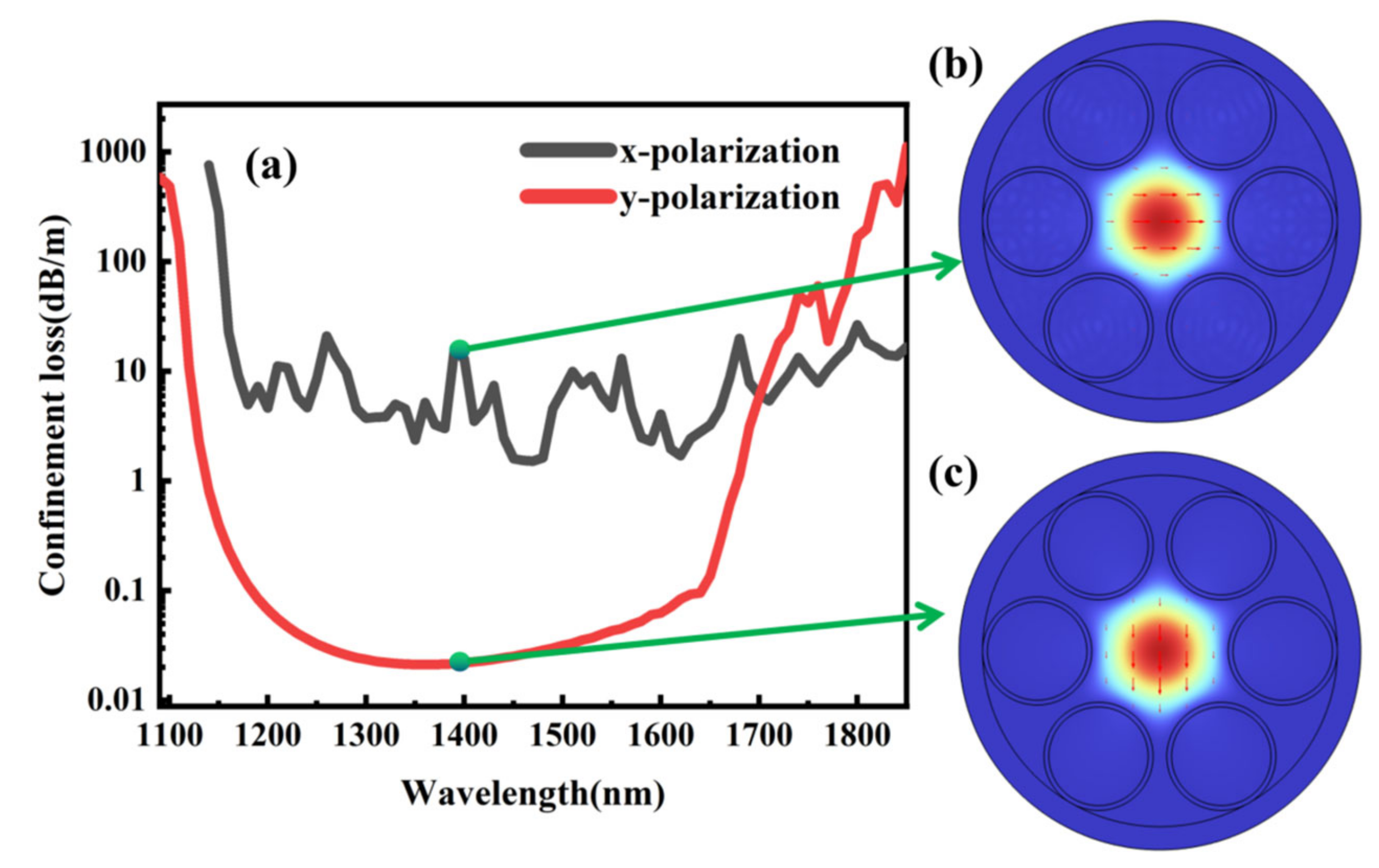
Figure 2a shows the confinement losses in the x-polarized and y-polarized FMs. Owing to the mode coupling, the FM loss of x-polarized light changes greatly with the wavelength but only fluctuates within the range of one order of magnitude. It can be seen that the FM loss of the two polarized states has a large difference at a wavelength of 1390 nm. Figure 2b,c show the electric field distribution of the x-polarized and the y-polarized FM at the wavelength of 1390 nm, with the direction of the electric field indicated by arrows. It can be seen that a small amount of energy from x-polarized FM diffuses into the cladding tube of the fiber, while the energy of y-polarized FM can effectively limit the core area.
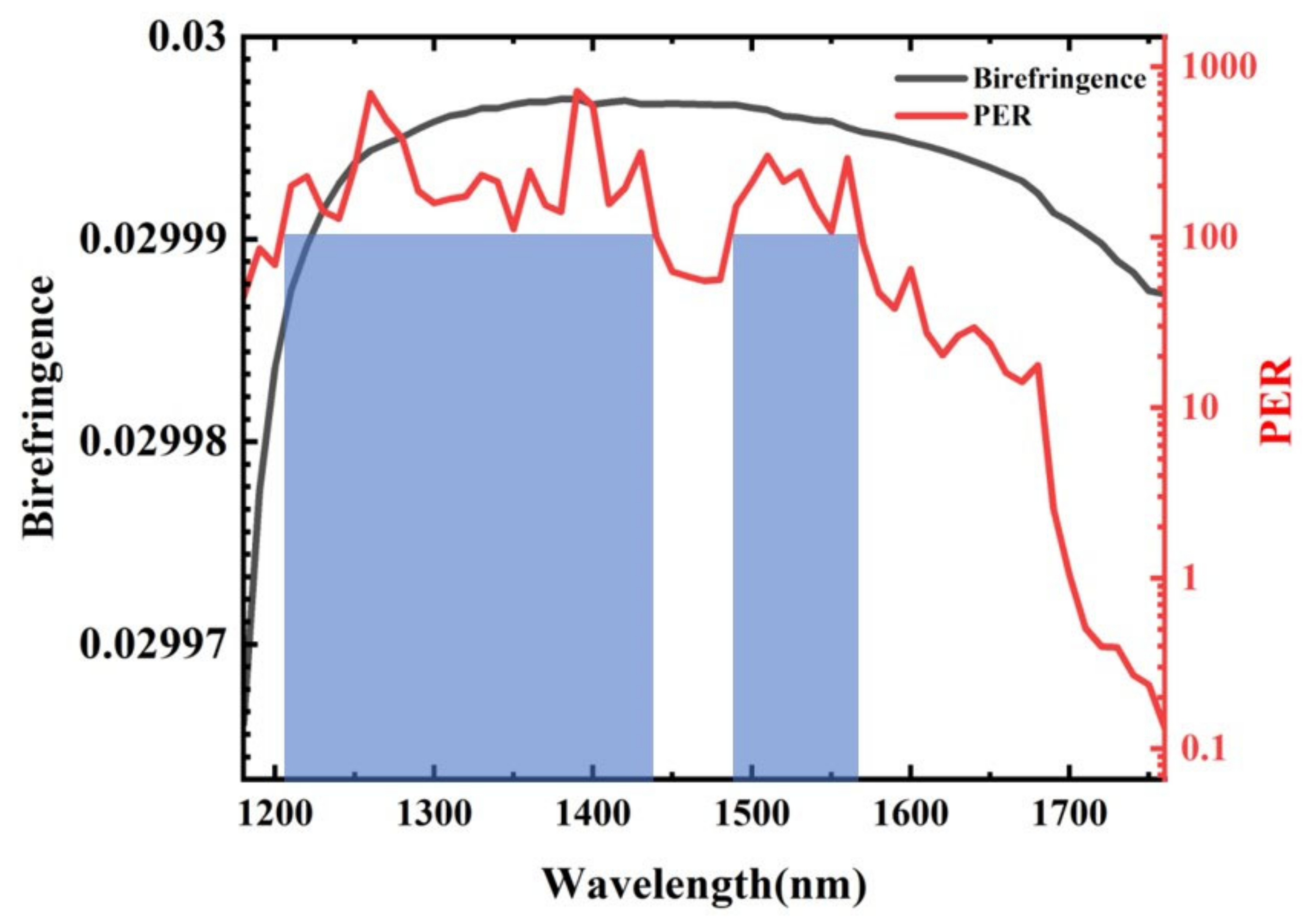
As shown in Figure 3, it shows the birefringence and PER of the fiber. It can be seen that there are two single-polarization regions (PER values greater than 100 are marked in blue columns) between 1210 nm and 1440 nm and 1490 nm and 1560 nm, respectively. The PER fluctuates due to the FM fluctuation of the x polarization, but wide single-polarization bandwidths of 230 nm and 70 nm can still be obtained.

3. Fiber Properties

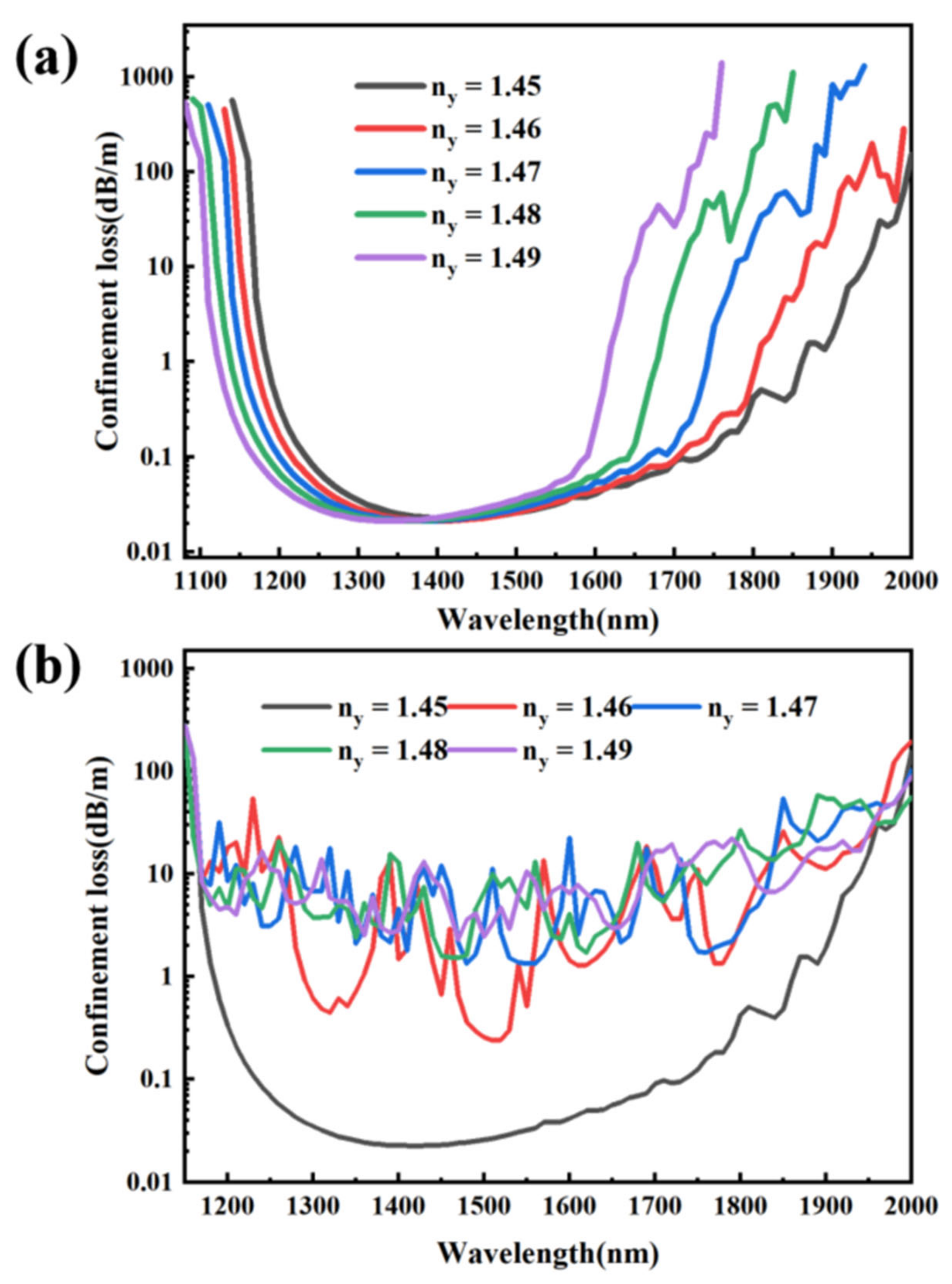
In this section, the properties of the proposed optical fiber with different structure parameters are discussed. Figure 4a presents the confinement loss of the FM in the y polarization direction for different ny. It can be seen that the confinement loss curve of the FM in the y polarization direction will move to the short wavelength direction when ny increases. Figure 4b shows the confinement loss of the FM in the x polarization direction for different ny. It can be seen that the confinement loss curve of the FM in the x polarization direction under different ny conditions will shake violently, and the smaller the ny, the greater the range of jitter. When ny increases, the confinement loss curve of the FM in the x polarization direction tends to move in the direction of increasing loss. It is worth noting that when ny increases from 1.45 to 1.46, the loss in the x-polarization direction increases rapidly by nearly two orders of magnitude, and then with the gradual increase of ny, the loss in the x-polarization direction gradually tends to be flat, so it is not advisable to blindly seek for greater anisotropy differences of glass materials. Considering the manufacturing process of the fiber-core glass material and the difficulty in manufacturing the target of the single-polarization region, ny is set to 1.48 in this paper.
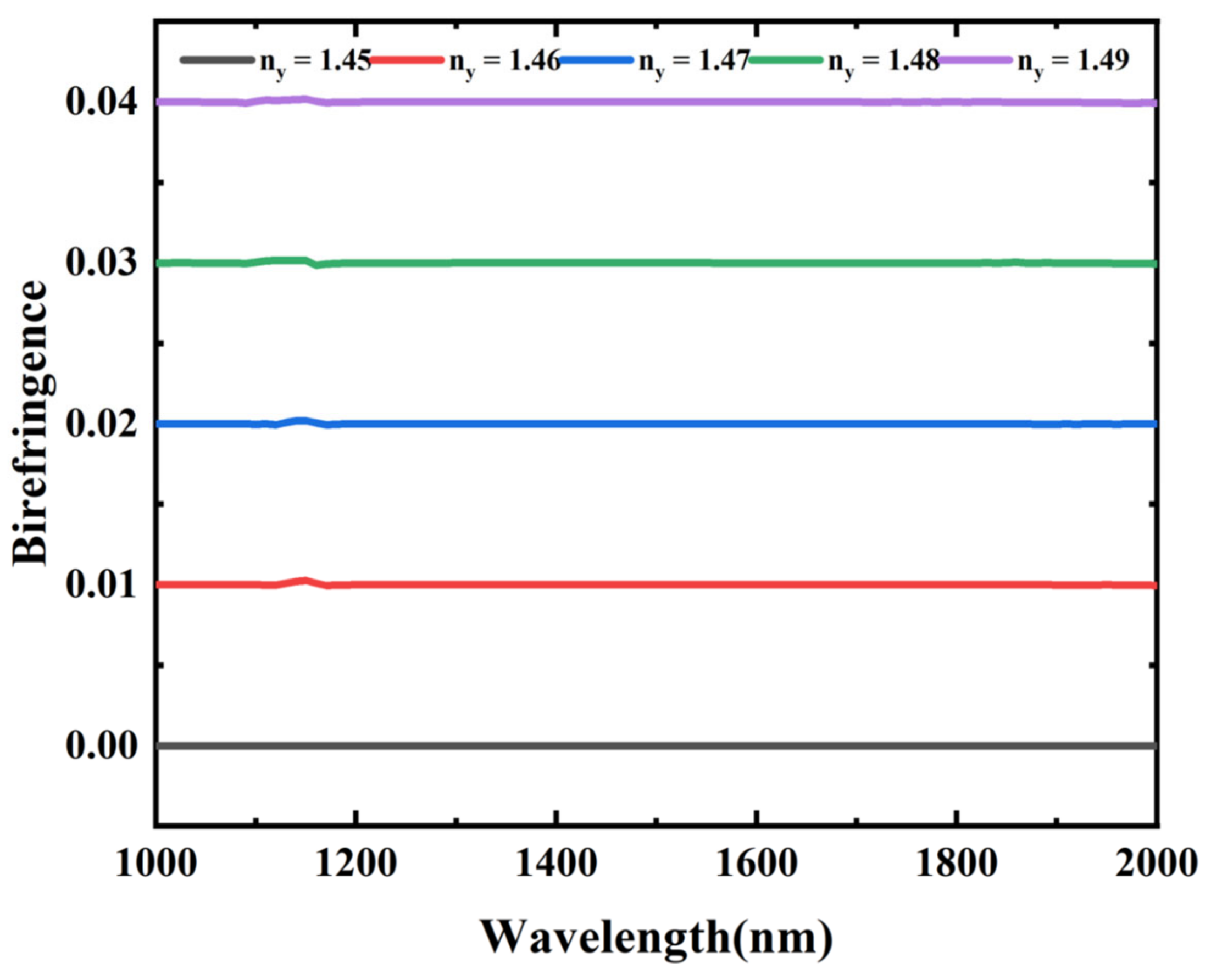
Figure 5 presents the birefringence of the fiber under different ny. With the increase of ny, the birefringence increases gradually but within an order of magnitude. Therefore, the anisotropy of anisotropic glass materials can effectively improve birefringence. Figure 6 shows the PER of the fiber under different ny. It can be seen that with the increase of ny, the PER value first increases rapidly and then becomes slow. According to the principle of anti-resonant fiber, when the refractive index of the cladding differs greatly from that of the core, a larger anti-resonant wavelength can be obtained. However, due to the use of different core refractive indexes nx and ny, there are two different anti-resonant wavelengths. For anti-resonant fibers, the p-polarization wave exhibits much worse light confinement than the s-polarization (the p-polarization wave direction is perpendicular to the cladding ring wall). Implying that, in the case of a hybrid polarization wave, the p-polarization component will play the primary role in light leakage [4]. From the analysis of the y-polarization direction, the p-polarization direction is the same as the y-polarization direction, and the change in ny has a significant impact on the anti-resonant wavelength. Therefore, as ny increases, the constrained loss curve of FM in the y polarization direction will move towards the short wavelength direction, showing that the transmission window (PER curve) follows. From the perspective of the x-polarization direction, the p-polarization direction is the same as the x-polarization direction, but the nx remains unchanged, which has little impact on the transmission window. Finally, the result shows that the two antiresonant wavelengths are comprehensively coupled. From the above analysis, it can be inferred that increasing the ny value can effectively improve the performance of the fiber. The ideal effect can be achieved by selecting the appropriate ny according to the target of the single-polarization region.
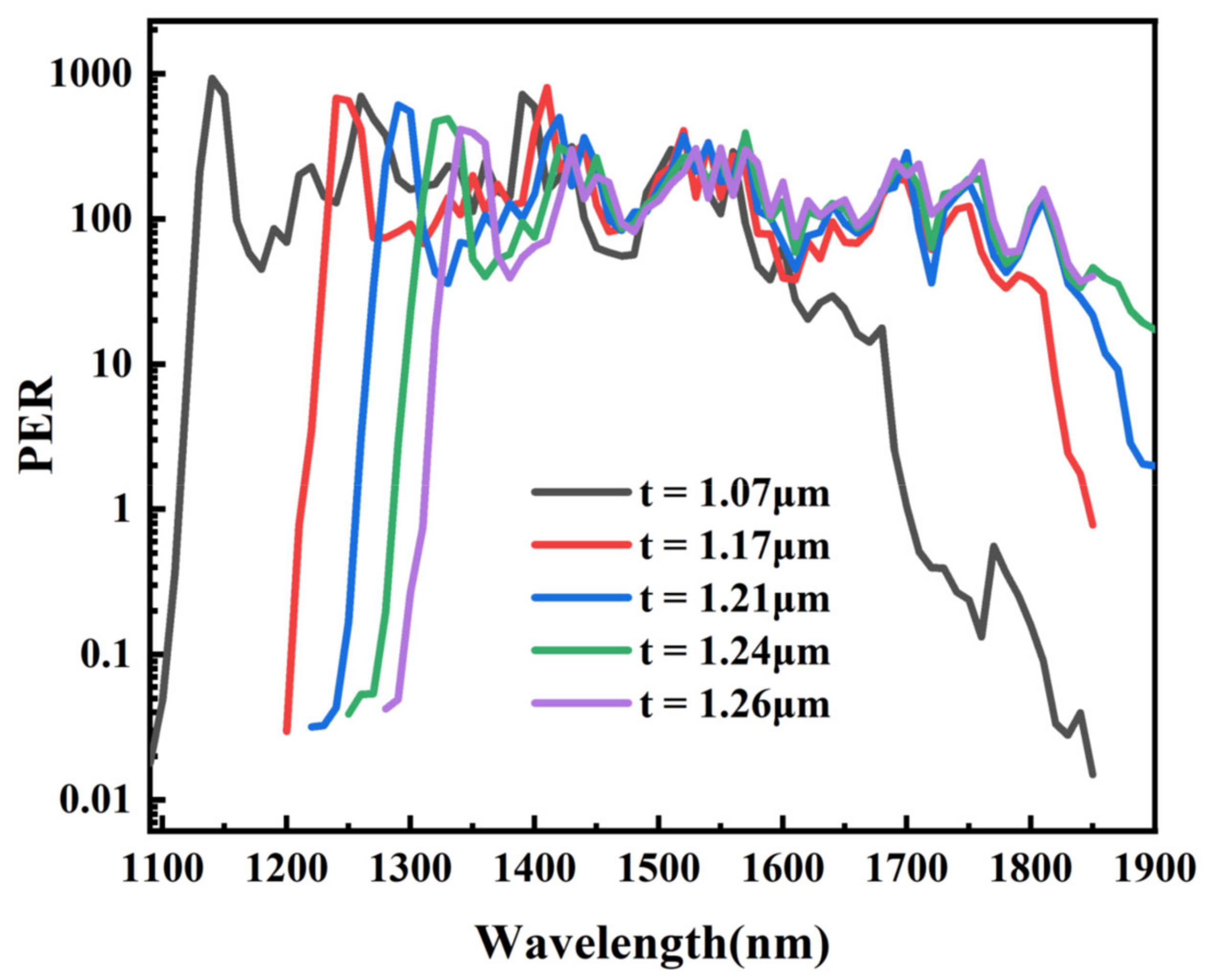
Figure 7 presents the losses in the x-polarized and y-polarized FM at the wavelength of 1550 nm and the PER of the fiber. It can be seen that when t = 1.2 μm, the maximum value of PER is 308. This means that we can adjust the polarization region of interest by changing the thickness of the tube. Figure 8 shows the change curve of fiber PER with wavelength for different tube thicknesses. It can be seen from Figure 8 that with the increase in tube thickness, the PER curve moves in the long wavelength direction and the changing trend becomes flat. According to Equation (1), the resonance wavelength is increasing as t increases, and the anti-resonance wavelength is positively correlated with the resonance wavelength. Therefore, the window of the PER will move in the long wavelength direction. Theoretical analysis is consistent with simulation results. To obtain a large single-polarization region in the near-infrared region, the fiber thickness is designed at 1.07 μm.
Table 1 shows a summary of the birefringence, PER, bandwidth, and critical bond radius of different SPF designs and provides a direct performance comparison of the fibers. Compared with other designed fibers, the fibers have higher birefringence and higher bandwidth. It can be seen that although SC-PBGF can obtain large bandwidth and high birefringence, its PER is low and cannot meet practical requirements. Currently, SC-ARF has a low birefringence of only 10−5 orders of magnitude and is often used as a polarization-maintaining fiber. Note that although HC-ARF can achieve good birefringence and an extremely high PER, manufacturing issues such as bandwidth and air hole collapse cannot be ignored. The designed fiber cannot only obtain a large PER but also a nice bandwidth.

4. Discussions and Conclusions

In 2021, Damian Michalik et al. tested the development of quartz all glass fiber with high birefringence and large mode area (HB-LMA), and the results proved that anisotropic glass can be successfully used as the core of the fundamental mode polarization component of C-band large core fiber [28]. In 2022, Alicja et al. reported the development of a quartz glass single-mode polarization-maintaining fiber with birefringence induced by the artificial anisotropic glass in a round core, and its loss can reach 0.1 dB/m [29]. Based on the above work, it is possible to use the subwavelength glass layer interlaced by high and low refractive index and use CVD technology to form an anisotropic fiber core with glass materials with a low refractive index and glass with a high refractive index, which ensures the possibility for the fabrication of the proposed SPSC-ARF.
In conclusion, we propose a novel six-ring SPSC-ARF based on anisotropic solid core materials. Based on the anisotropy of the fiber glass core material, two single-polarization operating regions (1210–1440 nm and 1490–1560 nm) are obtained. SPSC-ARFs with different structural parameters have been investigated. The optimized simulation results show that the ultra-wide single-polarization operating bandwidth of 230 nm and the maximum PER of 722 can be achieved. The difference in confinement loss between two orthogonal polarizations exceeds two orders of magnitude, and FM loss in the y-polarization direction is as low as 0.04 dB/m. Furthermore, these studies indicate that solid-core anti-resonant fiber might show great promise for ultrafast photonic applications [30,31,32], fiber-optic gyroscopes, and optical fiber communications.

Author Contributions

Conceptualization, W.L. and D.C.; methodology, W.L.; software, W.L.; validation, W.L. and B.Z.; formal analysis, A.X. and Z.D.; investigation, W.L.; resources, W.L. and D.C.; data curation, W.L. and D.C.; writing—original draft preparation, W.L., B.Z., Q.L. and Z.Y.; writing—review and editing, Z.Y. and Y.Z.; supervision, Z.G., Y.Z. and D.C. All authors have read and agreed to the published version of the manuscript.

Funding

This research was funded by the “Pioneer” and “Leading Goose” R&D Programs of Zhejiang (Nos. 2022C03084 and 2022C03066), the Zhejiang Provincial Natural Science Foundation of China (Nos. LQ22F050007 and LQ23F050004), and the Ningbo Science and Technology Project (No. 2021Z030).

Institutional Review Board Statement

Not applicable.

Informed Consent Statement

Not applicable.

Data Availability Statement

Not applicable.

Acknowledgments

We thank the Hangzhou Institute of Higher Studies of Zhejiang Normal University for its scientific help and support throughout this research.

Conflicts of Interest

The authors declare no conflict of interest.

References

  1. Shaw, L.B.; Kong, F.; Gu, G.; Hawkins, T.W.; Parsons, J.; Jones, M.; Dunn, C.; Kalichevsky-Dong, M.T.; Pulford, B.; Dajani, I.; et al. Polarizing 50 μm core Yb-doped photonic bandgap fiber. Proc. SPIE 2015, 9344, 934403. [Google Scholar] [CrossRef]
  2. Zhu, Y.; Song, N.; Gao, F.; Xu, X. Single-polarization single-mode hollow-core photonic-bandgap fiber with thin slab waveguide. Opt. Express 2021, 29, 30371–30383. [Google Scholar] [CrossRef] [PubMed]
  3. Yan, S.; Lou, S.; Zhang, W.; Lian, Z. Single-polarization single-mode double-ring hollow-core anti-resonant fiber. Opt. Express 2018, 26, 31160–31171. [Google Scholar] [CrossRef] [PubMed]
  4. Ding, W.; Wang, Y. Analytic model for light guidance in single-wall hollow-core anti-resonant fibers. Opt. Express 2014, 22, 27242–27256. [Google Scholar] [CrossRef] [PubMed]
  5. Yu, F.; Xu, M.; Knight, J.C. Experimental study of low-loss single-mode performance in anti-resonant hollow-core fibers. Opt. Express 2016, 24, 12969–12975. [Google Scholar] [CrossRef] [Green Version]
  6. Habib, M.S.; Bang, O.; Bache, M. Low-loss single-mode hollow-core fiber with anisotropic anti-resonant elements. Opt. Express 2016, 24, 8429–8436. [Google Scholar] [CrossRef] [Green Version]
  7. Chen, Y.; Saleh, M.F.; Joly, N.Y.; Biancalana, F. Low-loss single-mode negatively curved square-core hollow fibers. Opt. Lett. 2017, 42, 1285–1288. [Google Scholar] [CrossRef]
  8. Zhang, W.; Lou, S.; Wang, X.; Yan, S.; Tang, Z.; Xing, Z. A broadband single mode single polarization metal wires-embedded hollow core anti-resonant fiber for polarization filter. Opt. Fiber Technol. 2019, 53, 102011. [Google Scholar] [CrossRef]
  9. Yerolatsitis, S.; Shurvinton, R.; Song, P.; Zhang, Y.; Francis-Jones, R.J.A.; Rusimova, K.R. Birefringent Anti-Resonant Hollow-Core Fiber. J. Lightwave Technol. 2020, 38, 5157–5162. [Google Scholar] [CrossRef]
  10. Yu, F.; Cann, M.; Brunton, A.; Wadsworth, W.; Knight, J. Single-mode solarization-free hollow-core fiber for ultraviolet pulse delivery. Opt. Express 2018, 26, 10879–10887. [Google Scholar] [CrossRef]
  11. Alam, M.Z.; Tahmid, M.I.; Mouna, S.T.; Islam, M.A.; Alam, M.S. Design of a novel star type photonic crystal fiber for mid-infrared supercontinuum generation. Opt. Commun. 2021, 500, 127322. [Google Scholar] [CrossRef]
  12. Ghanbari, A.; Olyaee, S. Highly Nonlinear Composite-Photonic Crystal Fibers with Simplified Manufacturing Process and Efficient Mid-IR Applications. Crystals 2023, 13, 226. [Google Scholar] [CrossRef]
  13. Ahmad, R.; Komanec, M.; Zvanovec, S. Circular lattice photonic crystal fiber for mid-IR supercontinuum generation. IEEE Photonics Technol. Lett. 2016, 28, 2736–2739. [Google Scholar] [CrossRef]
  14. Hao, L.; Wang, X.; Jia, K.; Zhao, G.; Xie, Z.; Zhu, S. Narrow-linewidth. single-polarization fiber laser using non-polarization optics. Opt. Lett. 2021, 46, 3769–3772. [Google Scholar] [CrossRef] [PubMed]
  15. Cai, W.; Song, N.; Song, J.; Jin, J.; Wang, X. Transverse magneto-optic error of a miniature solid-core photonic-crystal fiber optic gyroscope. IEEE Access 2019, 7, 20106–20112. [Google Scholar] [CrossRef]
  16. Chen, X.; Antonelli, C.; Chandrasekhar, S.; Raybon, G.; Sinsky, J.; Mecozzi, A.; Winzer, P. 218-Gb/s single-wavelength, single-polarization, single-photodiode transmission over 125-km of standard singlemode fiber using Kramers-Kronig detection. In Proceedings of the Optical Fiber Communications Conference, Los Angeles, CA, USA, 19–23 March 2017. [Google Scholar] [CrossRef]
  17. Yan, S.; Lian, Z.; Lou, S.; Wang, X.; Zhang, W.; Tang, Z. Single-polarization single-mode hollow-core negative-curvature fiber with silicon-coated cladding. Opt. Quantum Electron. 2020, 52, 269. [Google Scholar] [CrossRef]
  18. Zhao, X.; Xiang, J.; Wu, X.; Li, Z. High birefringence, single-polarization, low loss hollow-core anti-resonant fibers. Opt. Express 2021, 29, 36273–36286. [Google Scholar] [CrossRef]
  19. Shang, L.; Feng, S.; Liu, G. Hole-Assisted Solid Core Bragg Fibers with a High-Index-Contrast Cladding for Broadband Single-Polarization Operation. J. Lightwave Technol. 2020, 38, 6104–6113. [Google Scholar] [CrossRef]
  20. Zhang, S.; Sun, S.; Sheng, Q.; Shi, W.; Yan, Z.; Yao, J. Low-loss polarization-maintaining solid-core anti-resonant fiber in mid-infrared region. Results Phys. 2021, 26, 104439. [Google Scholar] [CrossRef]
  21. Zhang, S.; Sun, S.; Sheng, Q.; Shi, W.; Yan, Z.; Tian, H.; Yao, J. Polarization-Maintaining Performance of Solid-Core Anti-Resonant Fiber with Nested Circular Tubes in 3 μm Wavelength. J. Lightwave Technol. 2022, 40, 1137–1143. [Google Scholar] [CrossRef]
  22. Payne, D.N.; Barlow, A.J.; Hansen, J.R. Development of low-and high-birefringence optical fibers. IEEE Trans. Microw. Theory Tech. 1982, 30, 323–334. [Google Scholar] [CrossRef]
  23. Urbanczyk, W.; Martynkien, T.; Bock, W.J. Dispersion effects in elliptical-core highly birefringent fibers. Appl. Opt. 2001, 40, 1911–1920. [Google Scholar] [CrossRef]
  24. Sihvola, A.H. Electromagnetic Mixing Formulas and Applications; The Institution of Electrical Engineers: Stevenage, UK, 1999. [Google Scholar]
  25. Wang, A.; George, A.K.; Liu, J.F.; Knight, J.C. Highly birefringent lamellar core fiber. Opt. Express 2005, 13, 5988–5993. [Google Scholar] [CrossRef]
  26. Waddie, A.J.; Buczynski, R.; Hudelist, F.; Nowosielski, J.; Pysz, D.; Stepien, R.; Taghizadeh, M.R. Form birefringence in nanostructured micro-optical devices. Opt. Mater. Express 2011, 1, 1251–1261. [Google Scholar] [CrossRef]
  27. Hsu, K.Y.; Yang, M.H.; Jheng, D.Y.; Huang, S.L.; Mennemann, K.; Dietrich, V.; Dubinskii, M. Single crystalline YAG-core fiber with a lanthanum dense flint glass cladding. In Proceedings of the 2013 Conference on Lasers and Electro-Optics Pacific Rim, CLEOPR 2013, Kyoto, Japan, 30 June–4 July 2013; pp. 1–2. [Google Scholar] [CrossRef]
  28. Michalik, D.; Anuszkiewicz, A.; Buczynski, R.; Kasztelanic, R. Toward highly birefringent silica Large Mode Area optical fibers with anisotropic core. Opt. Express 2021, 29, 22883–22899. [Google Scholar] [CrossRef] [PubMed]
  29. Anuszkiewicz, A.; Bouet, M.; Michalik, D.; Stepniewski, G.; Kasztelanic, R.; Filipkowski, A.; Pysz, D.; Cassez, A.; Klimczak, M.; Bouwmans, G.; et al. All-solid polarization-maintaining silica fiber with birefringence induced by anisotropic metaglass. Opt. Lett. 2022, 47, 401–404. [Google Scholar] [CrossRef] [PubMed]
  30. Li, X.; Huang, X.; Han, Y.; Chen, E.; Guo, P.; Zhang, W.; An, M.; Pan, Z.; Xu, Q.; Guo, X.; et al. High-performance γ-MnO2 Dual-Core, Pair-Hole Fiber for Ultrafast Photonics. Ultrafast Sci. 2023, 3, 0006. [Google Scholar] [CrossRef]
  31. Li, X.; Xu, W.; Wang, Y.; Zhang, X.; Hui, Z.; Zhang, H.; Wageh, S.; Al-Hartomy, O.A.; Al-Sehemi, A.G. Optical-intensity modulators with PbTe thermoelectric nanopowders for ultrafast photonics. Appl. Mater. Today 2022, 28, 101546. [Google Scholar] [CrossRef]
  32. Li, X.; An, M.; Li, G.; Han, Y.; Guo, P.; Chen, E.; Hu, J.; Song, Z.; Lu, H.; Lu, J. MOF-Derived Porous Dodecahedron rGO-Co3O4 for Robust Pulse Generation. Adv. Mater. Interfaces 2022, 9, 2101933. [Google Scholar] [CrossRef]
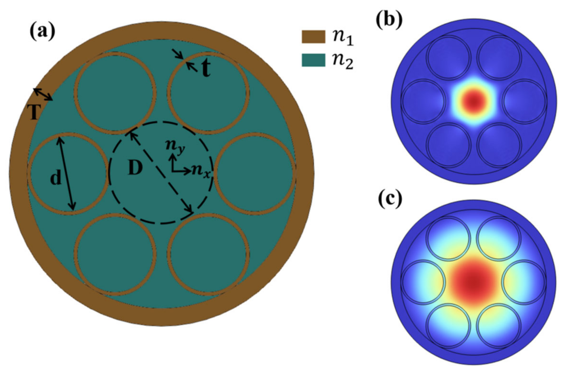
Figure 1. (a) Cross-section of the proposed SPSC-ARF and the electric field distributions of the FM at the wavelengths of (b) 1100 nm and (c) 1160 nm.
Photonics 10 00412 g001
Figure 2. (a) The losses in the x-polarized and y-polarized FM. The electric field distributions of the (b) x-polarized and (c) y-polarized FMs at the wavelength of 1390 nm.
Photonics 10 00412 g002
Figure 3. Birefringence (black curve) and PER (red curve) of the fiber.
Photonics 10 00412 g003
Figure 4. (a) The confinement losses in the y-polarized FM under different ny; (b) the confinement losses in the x-polarized FM under different ny.
Photonics 10 00412 g004
Figure 5. The birefringence of the fiber under different ny.
Photonics 10 00412 g005
Figure 6. The PER of the fiber under different ny.
Photonics 10 00412 g006
Figure 7. The confinement losses in the x-polarized and y-polarized FMs at 1550 nm wavelength and PER of the fiber.
Photonics 10 00412 g007
Figure 8. The PER of the fiber under different tube thickness.
Photonics 10 00412 g008
Table 1. The performance comparisons of the typical SPFs.
Fiber TypeMethodBirefringence/PERBandwidthRef.
HC-PBGFAdd thick TSW structure2.40 × 10−4/15 dB120 nm[2]
HC-ARFSilicon-coated double-ring cladding structure-/14,23215 nm; 10 nm; 30 nm[17]
HC-ARFNon-touching nested structure3.07 × 10−4/443212 nm[18]
SC-PBGFFill circular air holed10−3/15.7277 nm[19]
SC-ARFFill different materials1.56 × 10−5/--[20]
SC-ARFFill different materials3.07 × 10−5/--[21]
SC-ARFFiber-ore base on material anisotropy10−2/722230 nm; 70 nmThis work
Disclaimer/Publisher’s Note: The statements, opinions and data contained in all publications are solely those of the individual author(s) and contributor(s) and not of MDPI and/or the editor(s). MDPI and/or the editor(s) disclaim responsibility for any injury to people or property resulting from any ideas, methods, instructions or products referred to in the content.