Communication

Delivery of Nearly Diffraction-Limited Picosecond Laser Pulses in the Air-Filled Anti-Resonant Hollow-Core Fiber at 1 μm Wavelength

1
Key Laboratory of Materials for High Power Laser, Shanghai Institute of Optics and Fine Mechanics, Chinese Academy of Sciences, Shanghai 201800, China
2
Center of Materials Science and Optoelectronics Engineering, University of Chinese Academy of Sciences, Beijing 100049, China
3
Key Laboratory for Special Fiber and Fiber Sensor of Hebei Province, School of Information Science and Engineering, Yanshan University, Qinhuangdao 066004, China
4
School of Physics and Optoelectronic Engineering, Hangzhou Institute for Advanced Study, University of Chinese Academy of Sciences, Hangzhou 310024, China
*
Author to whom correspondence should be addressed.
These authors contributed equally to the work.
Photonics 2023, 10(4), 416; https://doi.org/10.3390/photonics10040416
Submission received: 16 March 2023 / Revised: 2 April 2023 / Accepted: 4 April 2023 / Published: 6 April 2023

Abstract

:
We demonstrate the damage-free delivery of nearly diffraction-limited picosecond laser pulses at 1064 nm with a maximum peak power of 3.5 MW in a 5 m air-filled anti-resonant hollow-core fiber (AR-HCF). In the air-filled AR-HCF, the transmission efficiency of picosecond pulses is degraded due to stimulated Raman scattering for the incident peak power above 3.59 MW. The temporal compression of pulses is also observed in the air-filled AR-HCF, where the self-phase modulation plays a key role in the anomalous dispersion region. By vacuuming the air in the core, a nearly constant coupling efficiency of 77% is achieved through the 5 m AR-HCF free of nonlinear effects, with M2 of the output beam less than 1.17.

1. Introduction

High energy ultrashort laser pulse is widely used in industrial micromachining/modification [1], laser surgery [2], and defense technology [3]. Despite the rapid development of high energy pico- and femtosecond laser technologies, the flexible delivery of ultrashort laser pulses via optical fiber remains a challenge [4]. Optical nonlinearities in traditional solid-core fibers, including the Kerr effect (mainly self-phase modulation, SPM), four-wave mixing, and stimulated Raman scattering (SRS), inevitably bring in nonlinear wavelength conversion, which degrades the spectral brightness of ultrashort pulses effectively. Although a shorter fiber length and a large core design are favorable to mitigate the impact [5], the fiber dispersion giving rise to the pulse distortion in the temporal domain inevitably limits the traditional optical fibers of long length in the ultrafast laser delivery.
Microstructured hollow-core fibers (MS-HCFs) provide a free-space-like propagation environment where the leaky loss is significantly reduced [6]. In principle, the guidance of light in the hollow core allows the laser transmission with a much higher average and peak powers beyond the damaging of the fiber host material. Moreover, MS-HCFs have both fiber dispersion and nonlinearity minimized, which have been demonstrated advantages in ultrafast laser delivery applications. Previously, photonic-bandgap hollow-core fibers (PBG-HCFs) and Kagome-HCFs as typical MS-HCFs have been extensively studied in the delivery of ultrafast laser pulses [7,8,9,10]. The newly emerged anti-resonant hollow-core fibers (AR-HCFs) further reduce the modal overlap with the glass structure down to around 10−4 to 10−5 [11] thanks to features of large core and negative curvature of core wall [12]. Therefore, the impact of the fiber material on the modal properties is much reduced. The laser damage threshold of AR-HCF is expected to be much beyond the traditional optical fiber. Meanwhile, AR-HCF presents a lower and more flattened dispersion and lower nonlinearity. The single-mode performance, large mode area, low dispersion, and low nonlinearity make AR-HCF a most promising medium for high-power short-pulse laser transmission for scientific and industrial applications [13].
AR-HCFs have been studied and applied in laser delivery over a broad spectral range from ultraviolet to mid-infrared [14,15,16,17,18,19]. High-peak-power, near-diffraction-limited laser pulse transmission has been achieved in AR-HCFs with reported output peak power exceeding hundreds of MW [20,21] when AR-HCF is vacuumed along the length. For the air-filled AR-HCF, a maximum peak power of around 15.3 MW was delivered, but the mode of output beam degraded with M2 of 3.2 due to the multimode behavior of the fiber [22]. In ref. [23,24], an AR-HCF was used to transmit peak power 0.34 MW over 5 m and kilowatt peak power over 300 m with the need to impose a large minimum bend diameter (~32 cm) to ensure acceptable bend losses. In ref. [25], 2.2-m argon-filled and vacuumed AR-HCFs were used to deliver peak power over 100 MW. In the ref. [26], a 5-m vacuumed AR-HCF was used to determine the relationship between beam quality and bending diameter. As demonstrated in some research, filling inert gas or vacuuming the air in the core was an effective method to eliminate the nonlinear effects in the beam transmission [25].
In this work, we successfully demonstrate the delivery of 3.5 MW high peak power picosecond laser pulses at 1064 nm over 5 m AR-HCF fiber length. We experimentally characterize the nonlinear spectral distortion and pulse duration shortening of laser transmission in air-filled AR-HCF, beam quality, and power propagation at the AR-HCF output as a function of incident power. The nonlinear spectral broadening is also theoretically simulated and discussed.

2. Experiment

2.1. AR-HCF

The homemade AR-HCF in this paper was fabricated by the stack-and-draw technique made of Heraeus F300 fused silica tubes. It consists of a single ring of seven capillaries forming the cladding (inset of Figure 1), with a core diameter of about 33 μm and an average capillary inner diameter of 20 μm. The 7-capillary cladding design of AR-HCF is preferred for an optimized balance between the single-mode guidance [27] and low leakage loss [28]. Figure 1 shows the measured attenuation of AR-HCF by the cut-back method, and 0.18 dB/m was obtained at 1064 nm wavelength.

2.2. Picosecond Pulsed Laser Source

The laser source under the AR-HCF delivery test is a Delphi Amber IR-25 laser, which consists of a picosecond pulsed fiber laser as the seed and a solid-state amplifier. Up to 25 W average power at 1064 nm wavelength emits with a maximum pulse energy of 66 μJ, pulse duration of 8.7 ps, and repeat frequency of 500 kHz. The water-cooled beam delivery optic and the remainder of the experimental setup are located in an interlocked laser safety enclosure. The measured beam quality has M 2 < 1.6 .

2.3. Experimental Setup

The experiment of picosecond laser pulse delivery by AR-HCF is shown in Figure 2. A Galileo system was used to scale the diameter of the laser beam to couple with AR-HCF. A 5-m-long AR-HCF was loosely rewound on an aluminum plate in a circle with a radius of about 20 cm without introducing a possible resonant bend loss [29]. It is noted that no cooling was applied in the experiment.
In the experiment, about 5 cm of the coating was stripped off at both fiber ends to avoid possible burning. At the input, the bare fiber end was mounted on a silica V-groove which was loaded in the homemade gas cell for vacuuming. The fiber end stuck out from the V-groove no longer than 3 mm against the possible wobble, causing the unstable coupling. Before the input, a sampler was used to monitor the incident power calibrating the coupling efficiency in real-time. At the AR-HCF output, the delivered laser power and beam quality were measured at the same time after the collimating lens (L4).

3. Results

3.1. Characterization of Power Transmission

Figure 3 shows the transmitted laser power of AR-HCF as a function of incident power. A 5-m-long AR-HCF was used, which was left in the atmosphere in the lab and filled with air. The transmission efficiencies for different incident power were also plotted, defined as:
T E = P o u t / P i n ,
where P o u t is the measured output power from AR-HCF and P i n is the measured incident power before AR-HCF.
As seen in Figure 3a, the output power of AR-HCF increased linearly as the incident power increased. The highest coupling efficiency was 87%, calculated by Equation (2) when the input power was lower than 14 W.
C E = T E × 10 α × L 10 ,
where α is the measured fiber attenuation (with the unit of dB/m), and L is the transmission length of the fiber.
As the incident power was increased, the transmission efficiency decreased. On the one hand, it was due to the mechanical drifting of the XYZ stage with the incident end of AR-HCF mounted. It was left without manual adjustment in the experiment. On the other hand, the stimulated Raman scattering of air in the hollow core was observed when TE decreased from 59% to around 54%, correspondingly with the incident power rising from 14 to 25 W.
The measured output spectra at the output of AR-HCF are shown in Figure 4. A peak centered at 1414 nm appeared in the output spectrum at input peak power above 3.6 MW, which is the first Stocks laser (S1) originating from vibrational stimulated Raman scattering (Vib-SRS) of a nitrogen molecule. Additionally, the anti-Stokes of the first order (AS1) was observed at 853 nm outside the low-loss transmission window of the fiber. By using band-pass and long-pass filters, the powers of the residual incident and S1 were measured, shown in Figure 3b. The first Vib-SRS power accounted for more than 7 W out of a total output of 13 W, where the maximum SRS efficiency approached 28%.
To eliminate the nonlinear effects of atmospheric air and maintain a constant transmission for all incident powers, we vacuumed AR-HCF by using two gas cells to seal the ends of AR-HCF. In order to avoid the influence of XYZ stage mechanical drift, the bulky gas cell was fixed on the experimental platform through a pedestal post (Thorlabs, TRP50/M). The measured pressure in the gas cell was around 800 Pa.
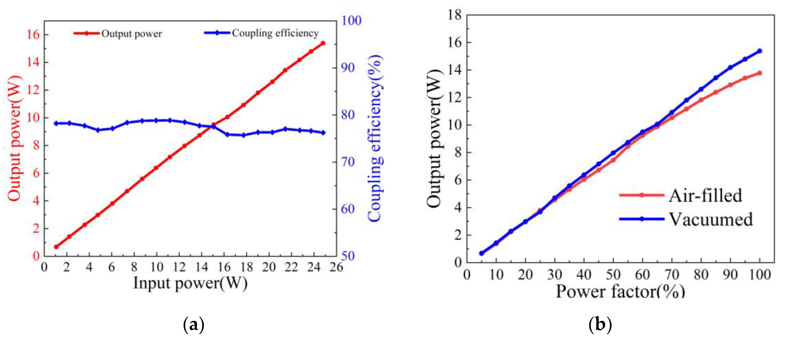
After vacuuming, the output power of AR-HCF increased linearly as the incident power increased, as shown in Figure 5a, and the CE was stable at around 77%, calculated by Equation (2) for incident power ranging from 1 to 25 W. After vacuuming the air in the core, the transmission efficiency was slightly lower. It was partially related to the slight tilting of AR-HCF after installation inside the gas cell. Without XYZ adjustment, the bulky gas cell was left still, and the coupling of AR-HCF was finely tuned by moving the lens, which makes it difficult to reach over 80% coupling efficiency. Figure 5b compares the delivered average laser power on the two conditions; the maximum output average power of the evacuated AR-HCF was 15 W, which is 2 W higher than that of the air-filled AR-HCF.
Measured spectra of the output beam through the vacuumed AR-HCF are shown in Figure 6. At a higher incident power, the laser spectrum was maintained, and SRS was no longer observed.

3.2. Characterization of Laser Beam Profile

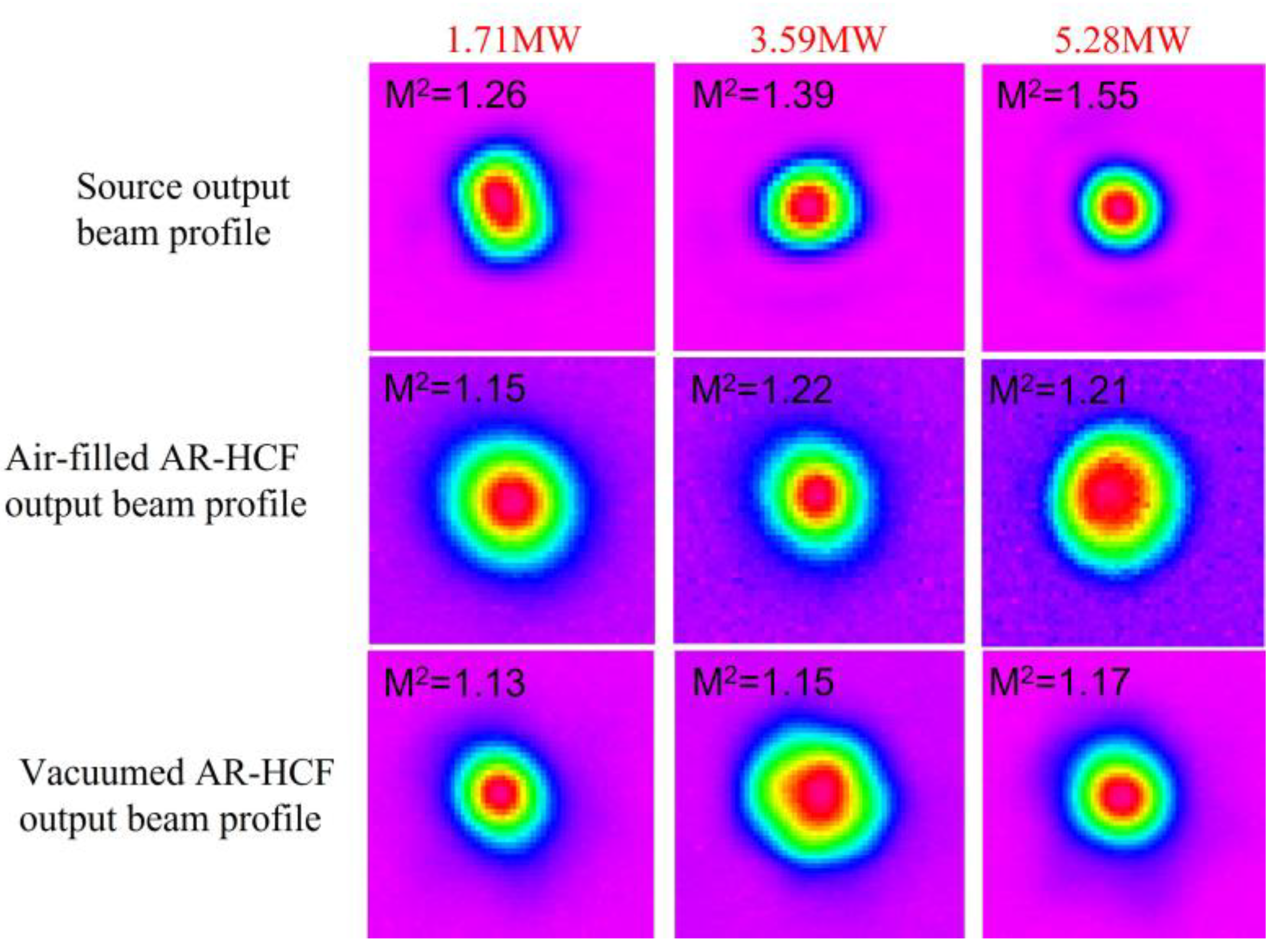
The laser beam profile at AR-HCF output was characterized for different incident powers, and the measured M2 factor is shown in Figure 7. The output beam quality of the laser source, air-filled AR-HCF, and vacuumed AR-HCF became degraded with the increase of power. However, at a similar incident power, the output beam quality of vacuumed AR-HCF was better than that of air-filled AR-HCF, both superior to that of the laser source. Although a higher peak power was delivered through similar air-filled AR-HCF in ref. [22], the mode of output beam degraded with M2 of 3.2 due to the multimode behavior of the fiber. Benefitting from the improvement of the single-mode guidance property of AR-HCF, the output beam quality of the laser source was improved after being delivered through AR-HCF in our work. In AR-HCF [30], higher-order modes often experience significantly higher losses, and after a relatively long length, the output beam profile is usually improved and regarded as ‘self-cleaning’. Benefiting from single-mode guidance and self-cleaning properties, delivery of nearly diffraction-limited was accomplished in AR-HCF. Here, we attributed the slightly worse beam profile to the output of air-filled AR-HCF due to the overlapping of modal profiled at multiple wavelengths.

3.3. Characterization of Laser Delivery in the Spectral and Temporal Domains

The evolution of delivered laser pulses in the spectral and temporal domains was characterized by different incident power. The comparison of the output spectrum between laser source, air-filled AR-HCF, and vacuumed AR-HCF is presented in Figure 8. As seen from the upper row and lower row of Figure 8, pulse spectral width was maintained at 1 nm with incident power increasing, and no significant difference appeared at laser delivery in the spectral domains. In the air-filled AR-HCF, the output spectrum (middle row in Figure 8) was spanned to 3 nm at the input peak power of 5.7 MW. Meanwhile, the spectral shape was altered as well.
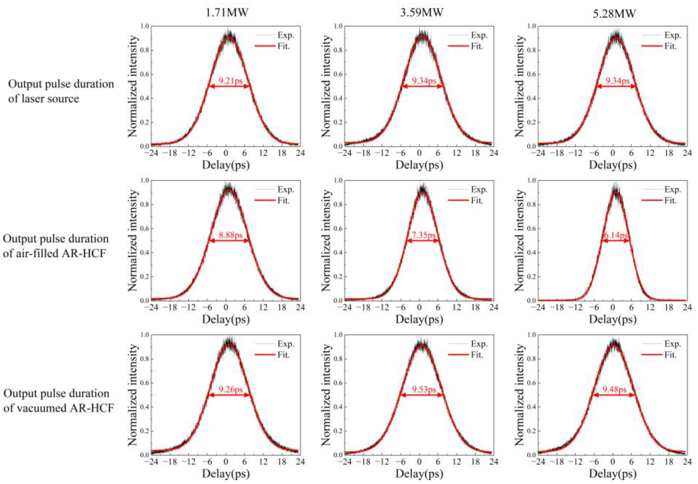
In Figure 9, the pulses duration of the laser source, air-filled AR-HCF, and vacuumed AR-HCF were characterized for different incident power. The pulse duration of the laser source was stable at around 9.3 ps for different power outputs. The pulse duration in air-filled AR-HCF became narrower at a higher incident power from 8.8 ps to 6.1 ps. After vacuuming, the pulse width was restored at the fiber output.

4. Discussion on Pulse Compression in the Air-Filled AR-HCF

4.1. Dispersion of AR-HCF

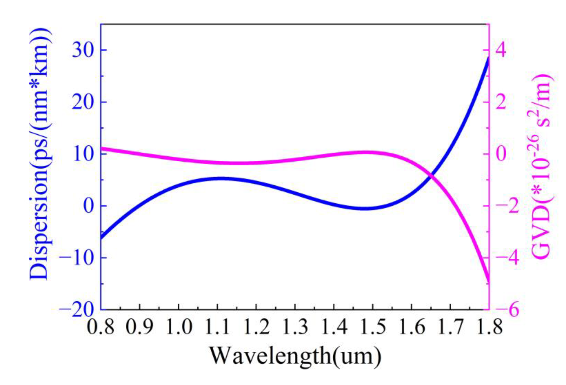
The group velocity dispersion (GVD) of AR-HCF is numerically calculated [31] and shown in Figure 10. At 1.064 μm, it is located in the flat region of the GVD curve, where D is 4.73 ps / nm · km and GVD is −2.84 s 2 / m . The zero-dispersion wavelengths (ZDW) of AR-HCF are calculated at approximately 905 nm, 1432 nm, and 1527 nm, respectively.

4.2. Numerical Simulation of Pulse Propagation in AR-HCF

We numerically simulate the pulse propagation in the air-filled AR-HCF to reproduce the pulse compression. Our simulation is performed by solving scalar, generalized nonlinear Schrödinger equation (GNLSE) numerically with the split-step algorithm: [32]
U ξ = i 1 2 U 2 τ 2 + i γ P 0 T 0 2 β 2 U 2 U ,
where input fields U = P 0 × sech T / T 0 , nonlinear parameters γ = n 2 λ 0 A e f f , P 0 is input pulse peak power, and T 0 is pulse duration. The nonlinear response of the fiber in the modeling takes into account the calculated effective area of the guided mode A e f f = 660   μ m 2 at 1064 nm and the nonlinear refractive index of the air n 2 = 6 × 10 23 m 2 / W . Attenuation and dispersion characteristics of the AR-HCF have also been included in the modeling.
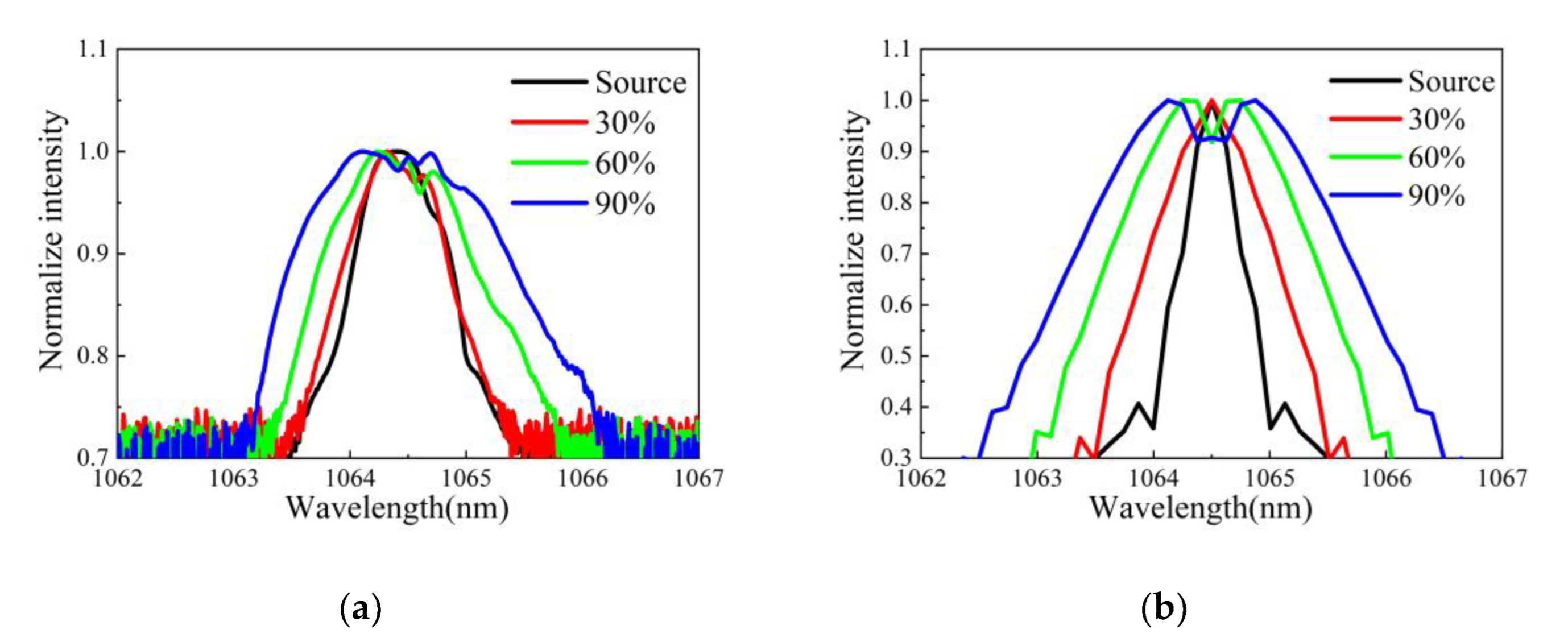
The measured spectral broadening at different incident powers and numerical simulations are compared in Figure 11. In the spectral domain, the simulated spectrum exhibits a good agreement with the experimental spectra at the same power. The broadening of the spectra occurs when increasing the incident power, which ultimately manifests itself as the SPM effect [33]. Thus, the maximum phase shift can be calculated by the Equation:
φ max = γ P 0 1 exp ( α L ) L ,
when input peak power is 3.59 MW and 5.28 MW, φ max has a value of 0.77π and 1.07π.
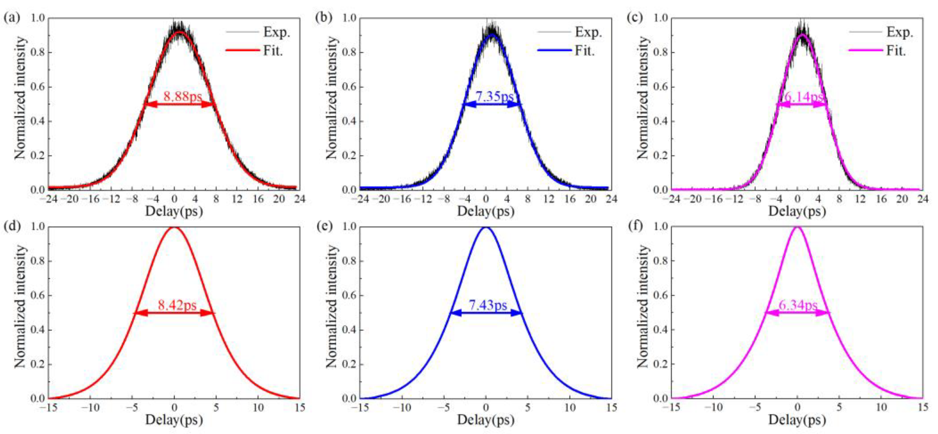
In the temporal domain, as seen in Figure 12, the spectrally broadened pulses are effectively compressed in the anomalous dispersion region. The redshift of the spectrum at the pulse front caused by the SPM effect slows down the motion of the pulse front and speeds up the motion of the pulse trailing edge due to the spectral blueshift, which in turn effectively compresses the pulse duration. In our case, apparently, the mixed effects of intense SPM and weak GVD result in impulse distortion of high energy laser pulse delivering through air-filled AR-HCF.

5. Conclusions

In this work, we systematically characterize the picosecond laser pulse delivery in a 5-m AR-HCF. Transmission/coupling efficiency, the evolution of pulses in the spectrum and temporal domain, and the output beam quality are experimentally measured. In the air-filled AR-HCF, SRS can be observed when the incident power reaches 14 W, and a maximum of Vib-SRS is measured at 7 W at 1414 nm wavelength. The interaction between SPM and GVD results in impulse distortion of high energy laser pulse in the transmission along the air-filled AR-HCF. The numerical simulation reproduces the pulse compression observed in the experiment. By vacuuming the air in the core, a nearly constant transmission efficiency of 77% is achieved through the 5-m AR-HCF, free of nonlinear effects, with M2 of the output beam less than 1.17. The existence of mechanical drift not only increases the damage probability of AR-HCF but also affects the long-term stability of output power. After fixing AR-HCF with a gas cell, the coupling efficiency of AR-HCF is much more stable, which is a better method to improve the long-term stability of output power. In the future, the small vacuum-encapsulated packaging of AR-HCF could replace the bulky gas cell to improve the long-term stability of high-energy pulse laser delivery.

Author Contributions

Methodology, L.L., X.Z. and F.Y.; Software, L.L. and Y.W.; Validation, L.L. and J.G.; Investigation, L.L., J.G. and F.Y.; Resources, D.W., Y.H. and F.Y.; Data curation, L.L. and J.G.; Writing—original draft preparation, L.L.; Writing—review and editing, X.Z. and F.Y.; Supervision, Y.H. and F.Y. All authors have read and agreed to the published version of the manuscript.

Funding

This work was supported by: National Key Research and Development Program of China (2020YFB1312802); Natural Science Foundation of Hebei Province (F2021203002); Chinese Academy of Sciences (Pioneer Hundred Talents Program, ZDBS-LY JSC020); National Natural Science Foundation of China (61935002); International Science and Technology Cooperation Program (2018YFE0115600); STI2030-Major Projects (2022ZD0212100).

Institutional Review Board Statement

Not applicable.

Informed Consent Statement

Not applicable.

Data Availability Statement

All the data in the diagram could be found in Liang, L. Delivery of nearly diffraction limited picosecond laser pulses in the air-filled anti-resonant hollow core fiber at 1 μm wavelength. Science Data Bank, https://cstr.cn/31253.11.sciencedb.07316 (accessed on 5 April 2023). CSTR:31253.11. sciencedb.07316.

Acknowledgments

We thank Suzhou Delphi Laser for providing the picosecond fiber laser source in our experiment.

Conflicts of Interest

The authors declare no conflict of interest.

References

  1. Tirlapur, U.K.; König, K. Targeted transfection by femtosecond laser. Nature 2002, 418, 290–291. [Google Scholar] [CrossRef] [PubMed]
  2. Farsari, M.; Chichkov, B.N. Two-photon fabrication. Nat. Photonics 2009, 3, 450–452. [Google Scholar] [CrossRef]
  3. Petrarca, M.; Henin, S.; Berti, N.; Matthews, M.; Chagas, J.; Kasparian, J.; Wolf, J.-P.; Gatti, G.; Di Pirro, G.; Anania, M.-P. White-light femtosecond Lidar at 100 TW power level. Appl. Phys. B 2014, 114, 319–325. [Google Scholar] [CrossRef] [Green Version]
  4. Eilzer, S.; Funck, M.C.; Wedel, B. Industrial fiber beam delivery system for ultrafast lasers: Applications and recent advances. High-Power Laser Mater. Process. Lasers Beam Deliv. Diagn. Appl. V 2016, 9741, 9–17. [Google Scholar]
  5. Agrawal, G.P. Nonlinear fiber optics. In Nonlinear Science at the Dawn of the 21st Century; Springer: Berlin/Heidelberg, Germany, 2000; pp. 195–211. [Google Scholar]
  6. Cregan, R.; Mangan, B.; Knight, J.; Birks, T.; Russell, P.S.J.; Roberts, P.; Allan, D. Single-mode photonic band gap guidance of light in air. Science 1999, 285, 1537–1539. [Google Scholar] [CrossRef] [Green Version]
  7. Hasan, I.; Akhmediev, N.; Chang, W. Empirical formulae for hollow-core antiresonant fibers: Dispersion and effective mode area. arXiv 2017, arXiv:1708.06879. [Google Scholar] [CrossRef]
  8. Andreana, M.; Le, T.; Drexler, W.; Unterhuber, A. Ultrashort pulse Kagome hollow-core photonic crystal fiber delivery for nonlinear optical imaging. Opt. Lett. 2019, 44, 1588–1591. [Google Scholar] [CrossRef]
  9. Resan, B.; Auchli, R.; Villamaina, V.; Holtz, R. Dynamic fiber delivery of 3 W 160 fs pulses with photonic crystal hollow core fiber patchcord. Opt. Express 2017, 25, 24553–24558. [Google Scholar] [CrossRef]
  10. Jones, D.; Bennett, C.; Smith, M.; Scott, A. High-power beam transport through a hollow-core photonic bandgap fiber. Opt. Lett. 2014, 39, 3122–3125. [Google Scholar] [CrossRef]
  11. Mulvad, H.; Abokhamis Mousavi, S.; Zuba, V.; Xu, L.; Sakr, H.; Bradley, T.; Hayes, J.; Jasion, G.; Numkam Fokoua, E.; Taranta, A. Kilowatt-average-power single-mode laser light transmission over kilometre-scale hollow-core fibre. Nat. Photonics 2022, 16, 448–453. [Google Scholar] [CrossRef]
  12. Belardi, W.; Knight, J.C. Effect of core boundary curvature on the confinement losses of hollow antiresonant fibers. Opt. Express 2013, 21, 21912–21917. [Google Scholar] [CrossRef] [PubMed]
  13. Yu, F.; Knight, J.C. Low loss anti-resonant hollow-core fibers and applications. In Proceedings of the 2017 19th International Conference on Transparent Optical Networks (ICTON), Girona, Spain, 2–6 July 2017; pp. 1–4. [Google Scholar]
  14. Yu, F.; Cann, M.; Brunton, A.; Wadsworth, W.; Knight, J. Single-mode solarization-free hollow-core fiber for ultraviolet pulse delivery. Opt. Express 2018, 26, 10879–10887. [Google Scholar] [CrossRef] [PubMed]
  15. Gao, S.-F.; Wang, Y.-Y.; Ding, W.; Wang, P. Hollow-core negative-curvature fiber for UV guidance. Opt. Lett. 2018, 43, 1347–1350. [Google Scholar] [CrossRef] [PubMed]
  16. Jaworski, P.; Yu, F.; Carter, R.M.; Knight, J.C.; Shephard, J.D.; Hand, D.P. High energy green nanosecond and picosecond pulse delivery through a negative curvature fiber for precision micro-machining. Opt. Express 2015, 23, 8498–8506. [Google Scholar] [CrossRef] [Green Version]
  17. Jaworski, P.; Yu, F.; MacLachlan, D.G.; Maier, R.R.; Thomson, R.R.; Wadsworth, W.J.; Knight, J.C.; Shephard, J.D.; Hand, D.P. A hollow-core Negative Curvature Fibre for efficient delivery of NIR picosecond and femtosecond pulses for precision micro-machining. In Proceedings of the Workshop on Specialty Optical Fibers and their Applications, Sigtuna, Sweden, 28–30 August 2013; p. F3-3. [Google Scholar]
  18. Krylov, A.A.; Senatorov, A.K.; Pryamikov, A.D.; Kosolapov, A.F.; Kolyadin, A.N.; Alagashev, G.K.; Gladyshev, A.V.; Bufetov, I.A. 1.56 µm sub-microjoule femtosecond pulse delivery through low-loss microstructured revolver hollow-core fiber. Laser Phys. Lett. 2017, 14, 035104. [Google Scholar] [CrossRef]
  19. Lee, E.; Luo, J.; Sun, B.; Ramalingam, V.L.; Yu, X.; Wang, Q.; Yu, F.; Knight, J.C. 45W 2 μm nanosecond pulse delivery using antiresonant hollow-core fiber. In Proceedings of the 2018 Conference on Lasers and Electro-Optics (CLEO), San Jose, CA, USA, 13–18 May 2018; pp. 1–2. [Google Scholar]
  20. Eilzer, S.; Wedel, B. Hollow core optical fibers for industrial ultra short pulse laser beam delivery applications. Fibers 2018, 6, 80. [Google Scholar] [CrossRef] [Green Version]
  21. Boullet, J.; Vinçont, C.; Bérisset, M.; Pierre, C. High energy ultrashort pulse delivery through hollow-core photonic crystal fiber. In Proceedings of the Components and Packaging for Laser Systems VII, Online, 6–11 March 2021; pp. 16–22. [Google Scholar]
  22. Jaworski, P.; Yu, F.; Maier, R.R.; Wadsworth, W.J.; Knight, J.C.; Shephard, J.D.; Hand, D.P. Picosecond and nanosecond pulse delivery through a hollow-core negative curvature fiber for micro-machining applications. Opt. Express 2013, 21, 22742–22753. [Google Scholar] [CrossRef] [Green Version]
  23. Michieletto, M.; Lyngsø, J.K.; Jakobsen, C.; Lægsgaard, J.; Bang, O.; Alkeskjold, T.T. Hollow-core fibers for high power pulse delivery. Opt. Express 2016, 24, 7103–7119. [Google Scholar] [CrossRef] [Green Version]
  24. Fu, Q.; Davidson, I.; Mousavi, S.; Xu, L.; Wheeler, N.; Poletti, F.; Richardson, D. Kilowatt-peak-power Green Pulse Delivery over Hundred-meter Scale Lengths of Hollow-Core Fiber. In Proceedings of the CLEO: Science and Innovations, San Jose, CA, USA, 15–20 May 2022; p. SW4K-8. [Google Scholar]
  25. Wu, S.; Siwicki, B.; Carter, R.M.; Biancalana, F.; Shephard, J.D.; Hand, D.P. Impact of nonlinear effects on transmission losses of hollow-core antiresonant negative curvature optical fiber. Appl. Opt. 2020, 59, 4988–4996. [Google Scholar] [CrossRef]
  26. Cai, Y.; Mai, Y.; Xiang, S.; Shi, J.; Zhu, Q.; Li, R.; Li, J.; Li, C.; Yan, D.; Xing, Y. Flexible Beam Delivery of Ultrafast Laser through Vacuum-Pumped Anti-Resonant Hollow-Core Fiber. Front. Phys. 2023, 11, 165. [Google Scholar] [CrossRef]
  27. Yu, F.; Xu, M.; Knight, J.C. Experimental study of low-loss single-mode performance in anti-resonant hollow-core fibers. Opt. Express 2016, 24, 12969–12975. [Google Scholar] [CrossRef] [PubMed] [Green Version]
  28. Song, P.; Phoong, K.Y.; Bird, D. Quantitative analysis of anti-resonance in single-ring, hollow-core fibres. Opt. Express 2019, 27, 27745–27760. [Google Scholar] [CrossRef] [PubMed]
  29. Carter, R.M.; Yu, F.; Wadsworth, W.J.; Shephard, J.D.; Birks, T.; Knight, J.C.; Hand, D.P. Measurement of resonant bend loss in anti-resonant hollow core optical fiber. Opt. Express 2017, 25, 20612–20621. [Google Scholar] [CrossRef] [PubMed]
  30. Ding, W.; Wang, Y. Analytic model for light guidance in single-wall hollow-core anti-resonant fibers. Opt. Express 2014, 22, 27242–27256. [Google Scholar] [CrossRef]
  31. Hasan, M.I.; Akhmediev, N.; Chang, W. Empirical formulae for dispersion and effective mode area in hollow-core antiresonant fibers. J. Light. Technol. 2018, 36, 4060–4065. [Google Scholar] [CrossRef]
  32. Dudley, J.M.; Genty, G.; Coen, S. Supercontinuum generation in photonic crystal fiber. Rev. Mod. Phys. 2006, 78, 1135. [Google Scholar] [CrossRef]
  33. Boyraz, O.; Indukuri, T.; Jalali, B. Self-phase-modulation induced spectral broadening in silicon waveguides. Opt. Express 2004, 12, 829–834. [Google Scholar] [CrossRef]
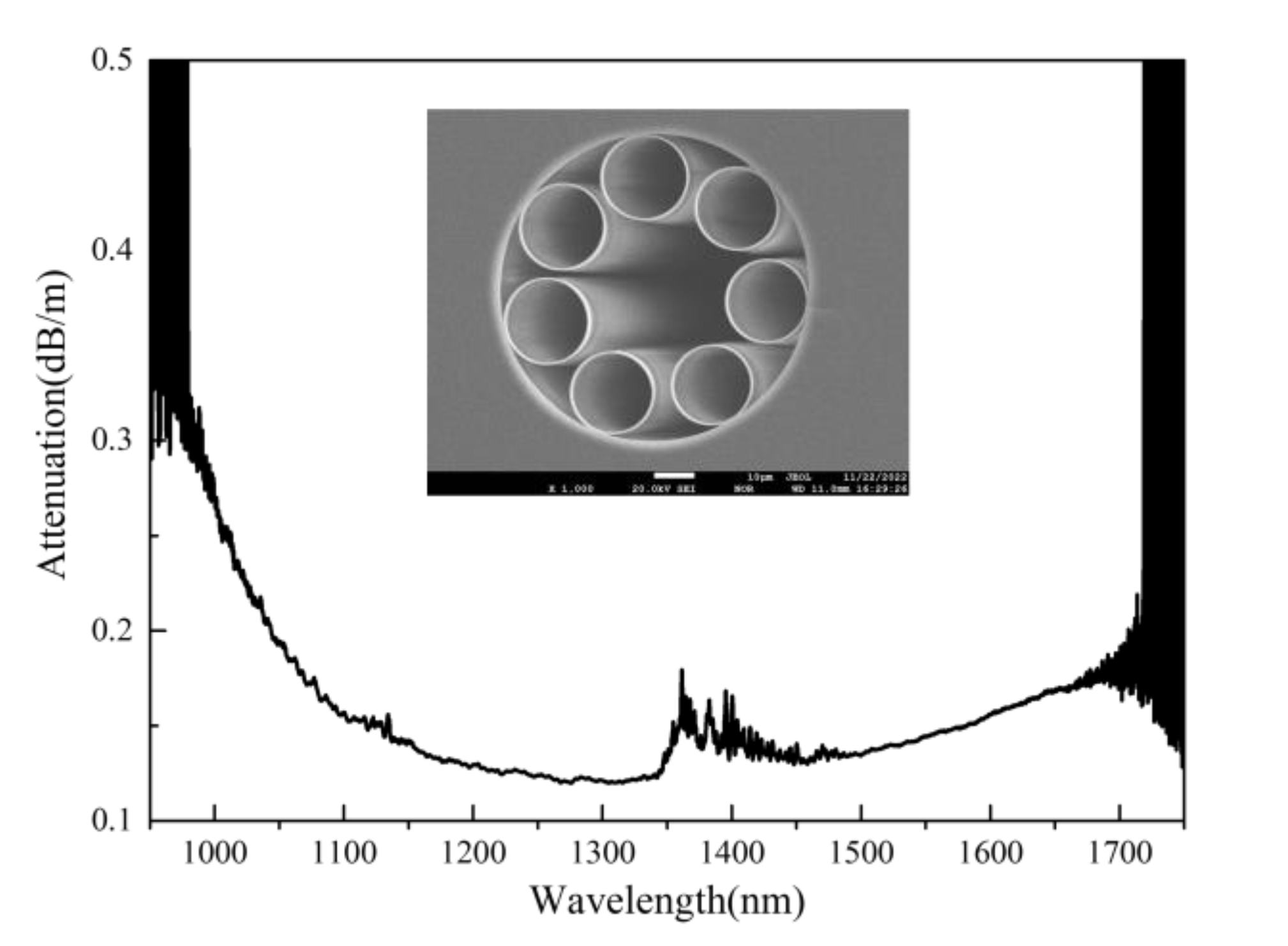
Figure 1. Measured attenuation of AR-HCF by a cut-back from 100 m to 10 m. Inset: SEM picture of AR-HCF. The core diameter is about 33 μm.
Photonics 10 00416 g001
Figure 2. Schematic of the laser delivery setup: L1, L2, L3, L4 are coated spherical lenses; M1, M2, M3 are dielectric mirrors; M4, M5 are back polished mirrors used as a sampler. PM1, PM2 are power meters. The AR-HCF is mounted on a silica V groove loaded in a homemade gas cell.
Photonics 10 00416 g002
Figure 3. (a) Measured output power and transmission efficiency as a function of incident power and (b) Measured powers of the residual incident and first Vib-SRS as a function of input power.
Photonics 10 00416 g003
Figure 4. Measured output spectra under air-filled AR-HCF for different incident power.
Photonics 10 00416 g004
Figure 5. (a) Vacuumed AR-HCF output power and coupling efficiency as a function of incident power and (b) Comparison of output power between 5 m air-filled and vacuumed AR-HCF.
Photonics 10 00416 g005
Figure 6. Measured output spectra under vacuumed (800 Pa) AR-HCF for different incident power.
Photonics 10 00416 g006
Figure 7. Beam profiles and corresponding M2 factors of the incident laser beam and output at the end of air-filled and vacuumed AR-HCF at input power of 1.71 MW, 3.59 MW, and 5.28 MW.
Photonics 10 00416 g007
Figure 8. Measurement output spectrum of laser source, air-filled AR-HCF, and vacuumed AR-HCF at peak power of 1.71 MW, 3.59 MW, and 5.28 MW.
Photonics 10 00416 g008
Figure 9. Measurement pulse duration of laser source, air-filled AR-HCF and vacuumed AR-HCF at peak power of 1.71 MW, 3.59 MW and 5.28 MW.
Photonics 10 00416 g009
Figure 10. Simulated dispersion and GVD of the investigated AR-HCF.
Photonics 10 00416 g010
Figure 11. Output spectrum of (a) experiment and (b) simulation at the same input pulse parameters.
Photonics 10 00416 g011
Figure 12. Compared output pulse duration of (ac) experiment and (df) simulation based on the same input pulse parameters.
Photonics 10 00416 g012
Disclaimer/Publisher’s Note: The statements, opinions and data contained in all publications are solely those of the individual author(s) and contributor(s) and not of MDPI and/or the editor(s). MDPI and/or the editor(s) disclaim responsibility for any injury to people or property resulting from any ideas, methods, instructions or products referred to in the content.