Communication

Prospects for the Implementation of an Intense Source of Ultraviolet Radiation Based on a Gas-Discharge Plasma in a Quasi-Optical Cavity Excited by a Pulse of Terahertz Radiation

1
Institute of Applied Physics, Russian Academy of Sciences, 603155 Nizhny Novgorod, Russia
2
Advanced School of General and Applied Physics, National Research University “N. I. Lobachevsky State University of Nizhny Novgorod”, 603950 Nizhny Novgorod, Russia
*
Author to whom correspondence should be addressed.
Photonics 2023, 10(4), 440; https://doi.org/10.3390/photonics10040440
Submission received: 22 March 2023 / Revised: 7 April 2023 / Accepted: 11 April 2023 / Published: 12 April 2023
(This article belongs to the Special Issue Terahertz Spectroscopy and Imaging)

Abstract

:
An electrodynamic system is described that provides the creation of an electromagnetic wave field of high intensity at a frequency of 1 THz due to a combination of accumulation in time and compression in space of a wave pulse coming from an electron cyclotron maser (gyrotron). This system is based on the use of a three-mirror cavity consisting of two focusing mirrors and one flat corrugated Bragg-type photonic structure providing coupling between the gyrotron wave pulse and the operating wave of the cavity. The aim of this work is to use a “spot” of the intense terahertz field inside the cavity to provide a point-like plasma discharge in a gas stream injected into this spot; such a discharge can be a source of extreme ultraviolet radiation.

1. Introduction

The terahertz (THz) frequency range, which occupies an intermediate position between the microwave and optical sections of the electromagnetic wave spectrum, has remained poorly studied for a long time. At the same time, this range has a number of specific features that make it very attractive for a wide range of fundamental and applied research in physics, chemistry, biology, and medicine [1,2,3,4,5,6,7,8,9,10].
In particular, the interaction of THz radiation with an inert gas stream creates the glow of a gas discharge plasma and can serve as a bright “point” source of optical and ultraviolet (UV) radiation. Indeed, it is known from previously performed experimental [11,12,13,14,15] and theoretical [16,17] works that the density of a gas-discharge plasma arising under the action of powerful sub-THz radiation of a gyrotron in a strongly inhomogeneous gas stream can significantly exceed the critical one, and such plasma effectively emits in the range of vacuum ultraviolet. To obtain plasma radiation in the region of extreme ultraviolet (EUF, wavelengths of 13–17 nm), good matching of radiation with the discharge plasma is necessary, thereby ensuring a large specific energy input of heating radiation into the plasma. The best matching is achieved when the characteristic size of the plasma formation is comparable to the length of the irradiating wave, and the electron concentration is several times higher than the critical one [16]. To do this, it is necessary to increase the frequency of the heating radiation to 1 THz. Focusing electromagnetic radiation with a frequency of 1 THz in principle allows the formation of a wave beam with a diameter of the order of a wavelength of 0.3 mm. Under such conditions, it is possible to create a plasma formation with a characteristic size of 0.3 mm and with a plasma density much higher than the critical concentration of 1016 cm−3. With a terahertz radiation power at a level of several kilowatts, the flux density will be about 106–107 W/cm2, which, according to estimates [17], should provide the essential necessary heating of the discharge plasma and its glow in the EUF frequency range.
To study the discharge under these conditions, sources of powerful coherent terahertz radiation are needed, since it is the shortage of sources of this type available to consumers that is the reason for the relatively low (to date) level of knowledge of the processes of interaction of THz frequency radiation with matter. For this reason, today the creation of any powerful THz source available to researchers is of independent interest. In particular, the use of electron cyclotron masers (gyrotrons) seems promising [18,19,20] (Figure 1a). Gyrotrons based on the use of moderately relativistic electron beams are significantly more compact as compared to the relativistic sources of the undulator radiation (free-electron masers) [21,22,23,24]. At the same time, as compared to the sourced based on the nonlinear optical rectification of powerful laser pulses [25,26], they provide a relatively long duration and a high degree of coherence of the output THz radiation. Within the framework of this approach, we are currently developing a gyrotron operating at the high (third) harmonic of the electron cyclotron frequency [19], which is unique in several characteristics at once. Firstly, the use of a relatively low-voltage (80–100 keV, 1 A) pulsed electron beam in a magnetic field of ~14 T, relatively low (for such frequencies) due to operation on the third cyclotron harmonic, ensures the relative compactness of such a generator. At the same time, in such a generator, it is possible to achieve an output coherent radiation power at the level of several kW in relatively long (tens of microseconds) pulses at a frequency of 1 THz [27].
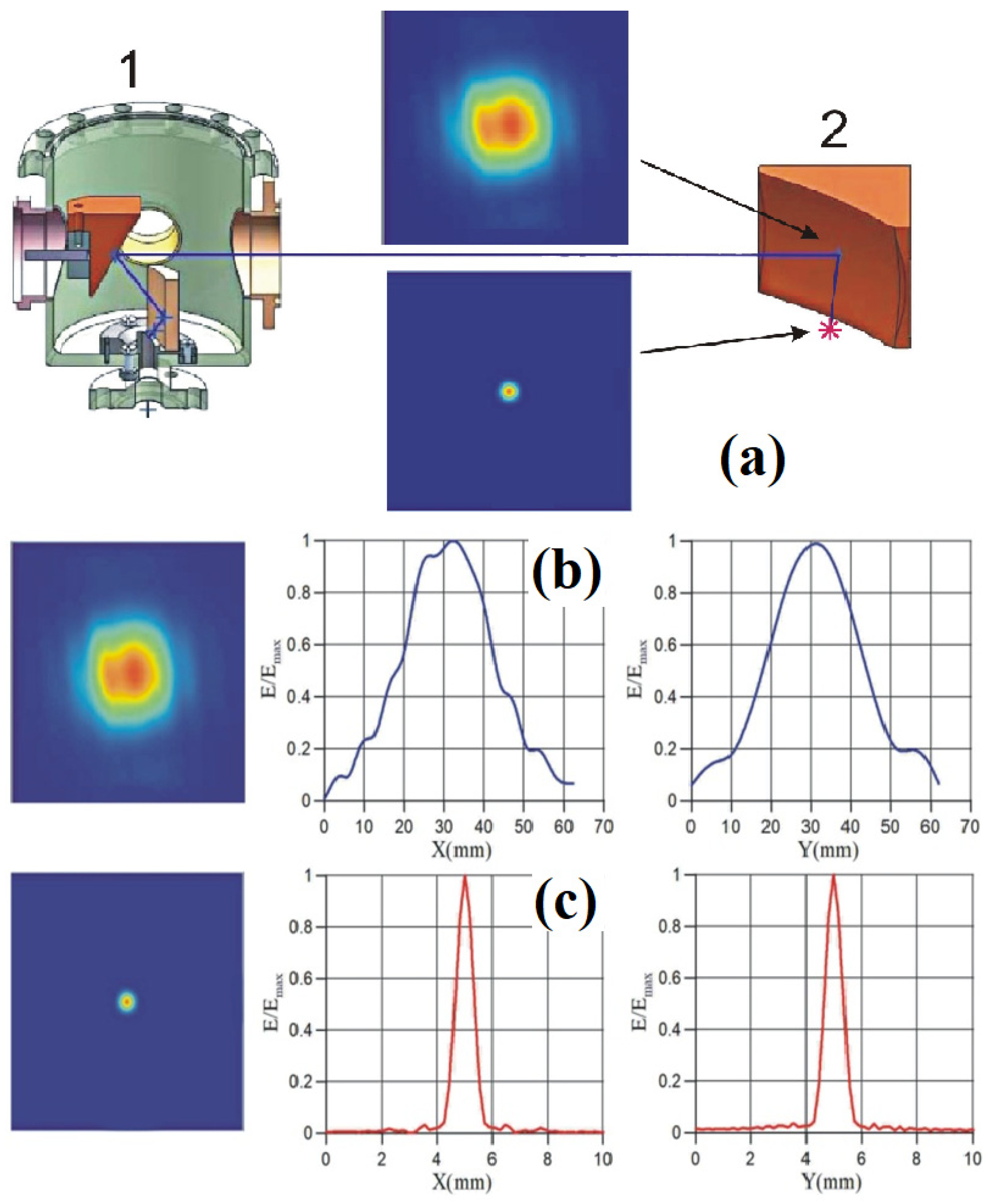
The gyrotron THz waves are radiated through the window (Figure 1a) in the form of a wave beam, allowing for the possibility of its subsequent focusing. In the traditional scheme (Figure 1b) of the organization of a terahertz discharge in plasma, the focusing system provides focusing until the formation of a wave beam with a diameter of about two wavelengths (0.6 mm at the wavelength of terahertz gyrotron radiation of λ ≅ 0.3 mm), which becomes close to the characteristic size of a point discharge plasma (Figure 2). In this case, the power flux density will be about 106 W/cm2 (the corresponding electric field strength is 20 kV/cm), which should ensure the ignition of the discharge in a wide range of pressures [28].
In this paper, as an alternative to direct focusing of the gyrotron output radiation (Figure 1b), a method is proposed that combines the necessary focusing with an increase in the intensity of the wave beam due to the accumulation of a wave signal inside a quasi-optical cavity (Figure 1c) [29]. The paper considers a three-mirror cavity consisting of two focusing mirrors and one flat with a corrugated surface (a Bragg-type photonic structure). The possibility of implementing this cavity at a frequency of 1 THz is discussed. The results of the calculations are given in relation to the structure of the output radiation of a gyrotron operating on the third cyclotron harmonic on the mode TE3,9 [19,27].

2. Calculations of a Quasi-Optical Cavity with a Traveling Wave

The excitation of a quasi-optical cavity with a traveling wave (Figure 3) is carried out due to the coupling between an external wave beam coming from the gyrotron and an operating wave beam of the cavity on a corrugated mirror (a Bragg-type scattering photonic structure). The corrugation period is selected in such a way that there is one (−1)th diffraction maximum coinciding with the wave beam in the cavity. The operating wave beam circulates in the cavity along a finite triangular trajectory. After each pass of the wave beam inside the cavity, it is partially scattered into a similar diffraction maximum coinciding with the mirror-reflected original beam. At the same time, there is no wave reflected from the cavity back to the gyrotron.
In the geometrical-optic approximation, the resonant frequencies correspond to the following condition:
k L = 2 n π .
Here, k = 2 π f / c is the wavenumber, c is the free space speed of light, L is the total length of the finite trajectory of the operating wave of the cavity, n 1 is the integer. The corrugated surface will be characterized by the spatial period d and the depth of the corrugation 2 A 0 and is described by the following formula:
A x = A 0 s i n 2 π d x .
The corrugation of the mirror is oriented with respect to the wave beam of gyrotron radiation so that the grooves of the corrugation are perpendicular to the plane of beam circulation inside the cavity and oriented parallel to the electric field of the wave beam. The condition of reflection of the input wave beam only in the mirror and (−1)-th diffraction maxima [30],
k · s i n θ 1 + s i n θ 2 = 2 π d ,
determines the value of the corrugation period, where θ 1 is the angle of incidence of the initial wave beam and θ 2 is the angle of reflection in the (−1)th diffraction maximum relative to the normal to the surface of the corrugated mirror. Choosing the angle of incidence of the wave on the surface of the corrugated mirror θ 1 = 60 0 , and setting the angle of reflection in the (−1)th max θ 2 = 20 0 , we get the period of the corrugation d = 0.83 λ.
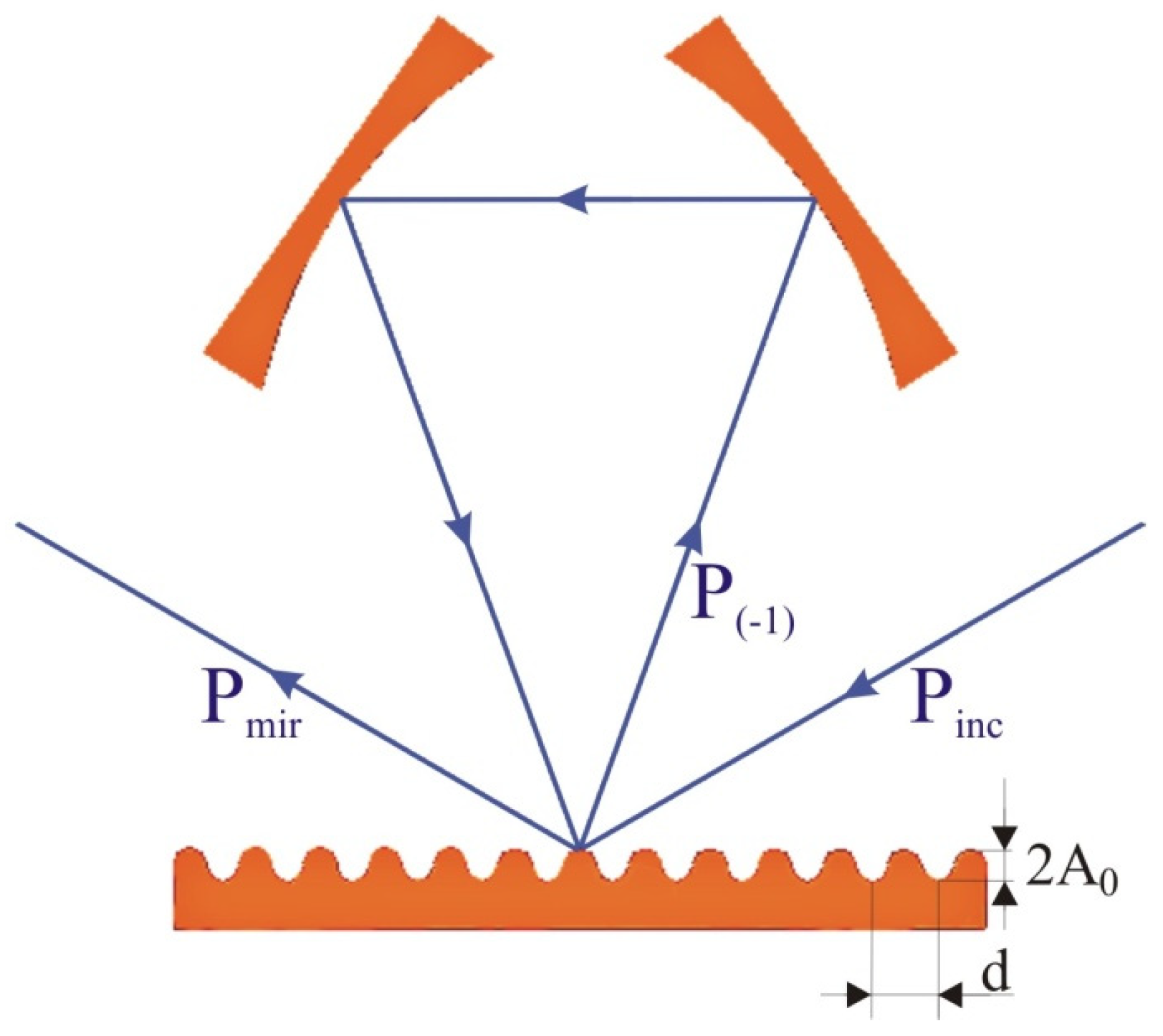
Based on the results of modeling the wave field pattern using the ANSYS HFSS code [31], when a plane wave P inc falls at an angle of 60 0 on a flat mirror with a corrugation period of 0.83 λ (Figure 4), the reflection coefficients of the wave beam into spatial harmonics were determined depending on the amplitude of the sinusoidal corrugation (Figure 5). Spatial harmonics correspond to (−1) to the diffraction maximum P ( 1 ) and the mirrored wave P mir .
The distances between the cavity mirrors correspond to the lengths of the sides of an isosceles triangle in the schematic of the cavity diagram shown in Figure 3. According to the simulation, these lengths amount 194 λ = 58.2 mm and 284 λ = 85.2 mm. As a result, the length of the finite trajectory of the operating wave beam in the cavity L = 762 λ = 228.6 mm is determined. At the same time, the angles of incidence of the wave relative to the normal to the mirror surface are 35 0 for focusing mirrors and 20 0 for a corrugated mirror. Ohmic losses on each of the three cavity mirrors are estimated according to the following Formula [32]:
δ o h m , i = 2 f σ c o s   θ .
In Formula (4), f = 1 THz is the frequency of radiation, σ is the conductivity taking into account the roughness of the mirror surface 0.8 microns,   θ is the angle of incidence of the wave relative to the normal to the mirror surface, δ o h m , i in the case of i = 1 and 2 are the ohmic losses on focusing mirrors. Ohmic losses on a mirror with a corrugated surface ( δ o h m , i in the case of i = 3) calculated by Formula (4) should be multiplied by a factor of 1.5, which occurs due to an increase in the path of the induced current through the sinusoidal surface. The total ohmic losses of the operating wave at one pass through the cavity amounts δ o h m = P o h m / P 0 = i = 1 3 δ o h m , i . The results of the ohmic loss estimation for a cavity with cooper mirrors are summarized in Table 1. In these calculations, the conductivity of copper was reduced by 10 times (compared to ideal copper) to account for the increase in ohmic losses in the THz frequency range due to the inevitable roughness of the mirror walls.
Under the condition that the diffraction beam spatially coincides with the wave beam in the cavity at the resonant frequency determined by Equation (1), the power gain of the operating wave in the cavity (the ratio of the power of the wave traveling in the cavity to the power of the exciting beam),
G = P 0 / P inc = E 0 2 / E inc 2 .
is defined by the following expression [29]:
G = r 2 1 1 r 2   · e α / 2 2 .
Here r 2 = P 1 / P inc is the power reflection coefficient of the wave beam exciting in the (−1)th diffraction maximum. In addition, the coefficient r 2 = δ com determines the diffraction power loss in the direction of the “mirror” spatial harmonic. Thus, r 2 is the coupling coefficient with the external exciting and radiated wave. The value of α is determined by the following expression:
1 e α = P los / P 0 ,
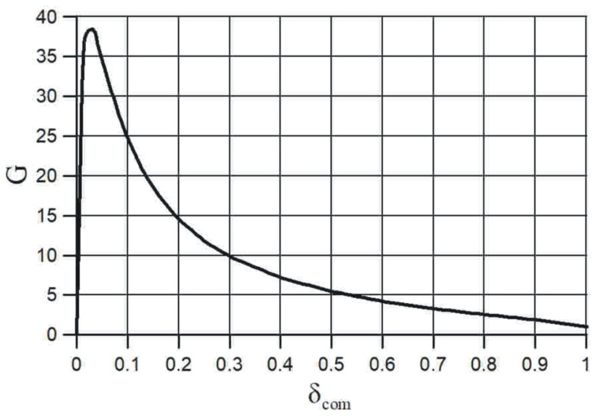
where P los is the own power loss of the operating wave during one pass through the cavity. In our case, these are ohmic losses. In the case of δ ohm = 0.026 the maximum gain value G max 38.5 is achieved at δ com = 0.03 , and it decreases with a further increase in the coupling coefficient with the external wave (Figure 6).
If we know the length of one pass of the traveling wave through the cavity (the effective length of the cavity), the power loss of the operating wave during one pass through the cavity, and the power loss in the process of coupling with the external wave, it is possible to estimate the loaded Q-factor of the cavity:
Q = k L δ ohm + δ com .
In this case, the resonance frequency width is expressed as follows:
Δ f = f Q .
An important parameter that determines the realizability of the cavity is the accuracy of its length adjustment, i.e., the position of the mirrors,
Δ L < L Q = δ ohm + δ com 2 π   λ .
According to (9), in order to reduce the accuracy of the cavity length adjustment for an operating frequency of 1 THz to acceptable values, it is necessary to increase the loss of coupling with the external wave by choosing the appropriate amplitude of the corrugation (Figure 5) and thereby reduce the intensity gain of the operating wave in the cavity (Figure 6). The specified cavity parameters for two variants of the amplitude of the corrugation are summarized in Table 2.

3. Focusing a Wave Beam in The Cavity

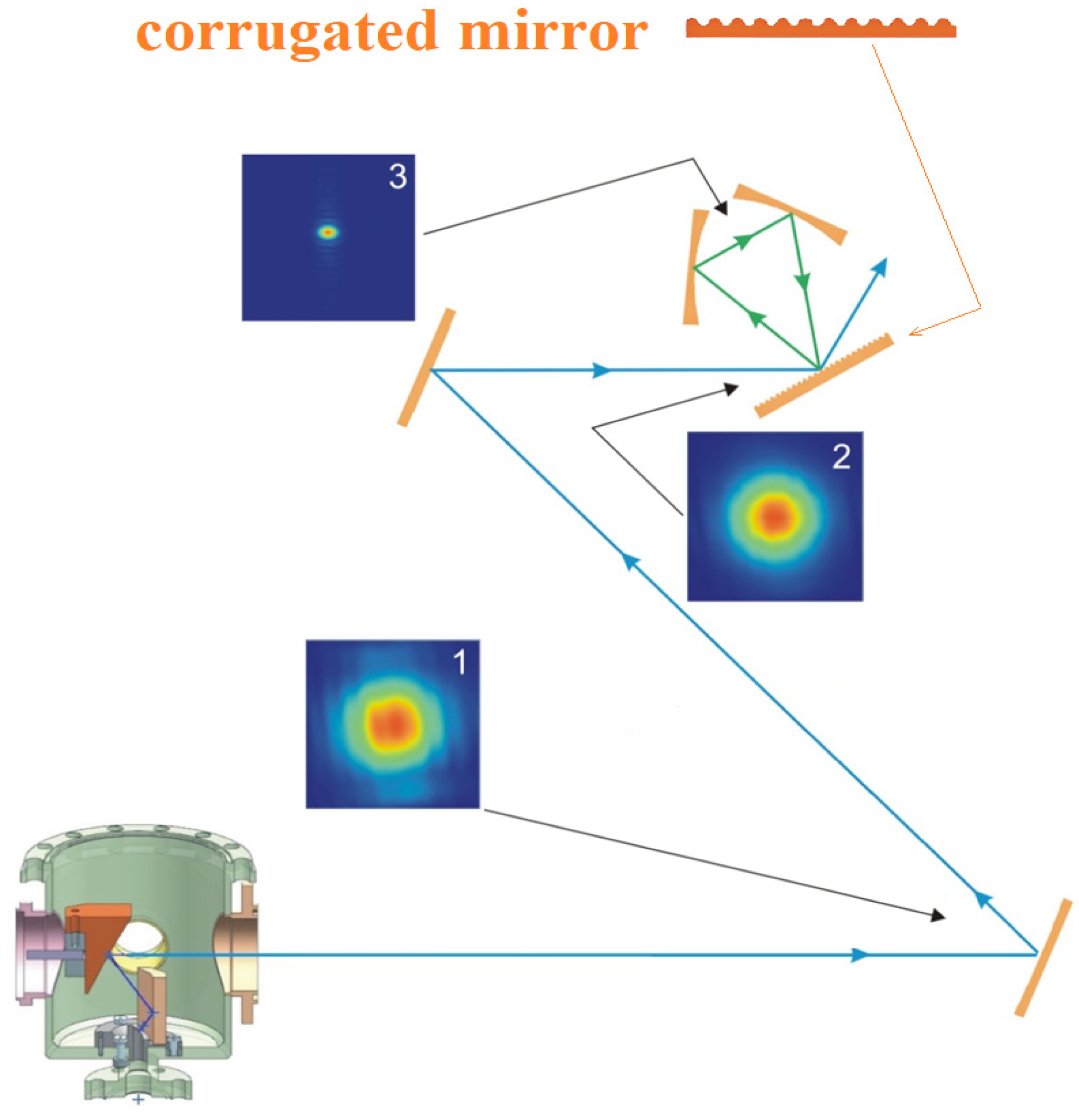
When calculating the focusing mirrors, the formation of a wave beam in the gyrotron wave converter (Figure 1a) and at the entire distance before the wave falls on the corrugated mirror of the cavity has been considered (Figure 7). Modeling the excitation of the cavity by an external wave beam shows that for high-quality focusing of the wave beam circulating in the cavity, the cavity should be excited by a plane wave with a quasi-Gaussian distribution of the field amplitude in the cross section.
In accordance with these considerations, the wave beam coming from the gyrotron output is additionally corrected by a system of two mirrors in order to obtain a quasi-Gaussian amplitude distribution with a flat phase front in the cross section of the beam exciting the cavity (Figure 8). The profile of the focusing mirrors was calculated under the condition of compensation for the diffraction spreading of the wave beam and the formation of the minimum possible constriction in the focus point of the mirrors located at half the distance between their centers.
When the cavity is excited by an external signal in the form of an adjusted wave beam, the operating wave beam with a waist of about 0.3 mm is formed between the focusing mirrors of the cavity (Figure 9). At the same time, according to the calculation, the ratio of electric field strengths in the beam cross sections between the focusing mirrors and the input wave beam is about 68 times.

4. Increasing the Electric Field Strength

In the process of pumping the cavity with an external wave, the electric field strength in the circulating wave beam increases with each of its passes through the cavity. Of interest is the rate of increase of the field amplitude in the cavity with different coupling with an external exciting signal. We compare two versions of the cavity with the parameters given in Table 2. To describe the process, we take the amplitude of the field of the wave incident on the corrugated mirror equal to 1. For a unit of time, it is natural to choose the time of a single passage of the wave in the cavity τ = L / c . The number of wave passes in the cavity is denoted by n N = ΔT/τ, where ΔT is the duration of the microwave pulse. Then the process of increasing the amplitude of the field in the cavity under the condition of resonance (1) is described by the following formula:
E n = E inc r × 1 1 r 2 e α 2 n 1 1 r 2 e α 2 .
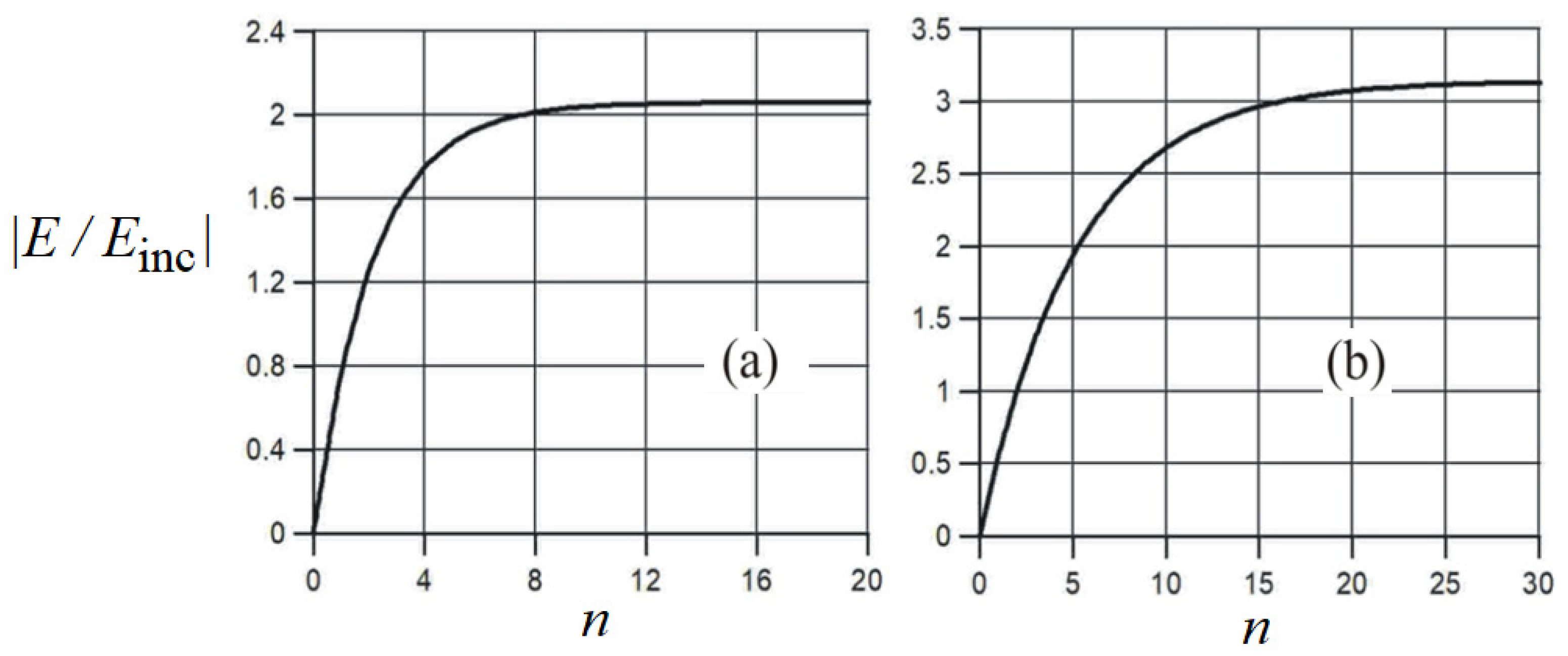
In a cavity with a corrugated mirror having a corrugation amplitude of A0 = 0.33 λ and coupling losses with an external wave δ com = 0.6 , the amplitude of the electric field of the wave reaches twice the value compared to the field of the external beam and goes to the stationary state after 12 passes through the cavity, which corresponds in time to 10 ns (Figure 10a). In a cavity having a corrugation amplitude of A0 = 0.17 λ and coupling losses with an external wave δ com = 0.3 , the amplitude of the electric field of the wave reaches a tripled value compared to the field of the external beam and reaches the stationary after 25 passes through the cavity, which corresponds in time to 20 ns (Figure 10b). In comparison with the duration of the radiation pulse of several tens of microseconds, the amplitude of the electric field intensity in the cavity is almost instantaneous.
Thus, we have a significant (68 times) increase in the electric field strength compared to the field of the input wave beam due to beam focusing between the focusing mirrors of the cavity and an additional increase in the amplitude of the electric field strength of the wave by 2 and 3 times, respectively, due to accumulation of the wave field inside the cavity. As a result, the intensity of the electric field in the focus point of the cavity mirrors increases by 136 times and 204 times compared to the amplitude of the field of the external beam with a corrugation amplitude of 0.1 mm and 0.05 mm, respectively. Having assumed that the power of the external wave beam is 3 kW, we see that the electric field strength in the focus of the cavity mirrors can reach 80 kV/cm and 120 kV/cm, respectively, which exceeds the electric field value obtained by direct focusing by 4 and 6 times.

5. Discussion

Summing up the results of the calculations, it can be concluded that, despite the high pumping frequency (1 THz) and, therefore, a huge oversize factor (the ratio between typical sized to the wavelength) of the operating cavity, as well as despite the pulsed character of the output wave signal of the gyrotron, it is possible to propose a cavity that ensures both effective accumulation of the wave signal in time and focusing of the wave in space simultaneously. The use of a quasi-optical cavity with a traveling wave and with a Bragg-type photonic structure providing coupling between the gyrotron wave pulse and the operating wave of the cavity makes it possible to obtain the electric field strength required for breakdown at lower generator power values compared to the case of direct focusing. According to our estimations, the electric field strengths in the focus of the mirrors of the cavities used to accumulate the gyrotron wave signal exceed the electric field value obtained by direct focusing by four to six times. This can greatly simplify the task of creating an extreme ultra-violet source based on gas-discharge plasma.

Author Contributions

Conceptualization, Y.K. and A.S.; methodology, Y.K. and G.K.; software, Y.K. and G.K.; validation, G.K., Y.K. and A.S.; formal analysis, G.K. and Y.K.; investigation, Y.K. and G.K.; writing—original draft preparation, Y.K. and G.K.; writing—review and editing, A.S. and Y.K. All authors have read and agreed to the published version of the manuscript.

Funding

This work was supported by the Russian Science Foundation, grant No. 19–19–00599.

Acknowledgments

The authors are grateful to A. Vodopyanov and A. Sidorov for their key contribution in initiating our work on this topic.

Conflicts of Interest

The authors declare no conflict of interest.

References

  1. Liu, M.; Hwang, H.Y.; Tao, H.; Strikwerda, A.C.; Fan, K.; Keiser, G.R.; Sternbach, A.J.; West, K.G.; Kittiwatanakul, S.; Lu, J.; et al. Terahertz-field-induced insulator-to-metal transition in vanadium dioxide metamaterial. Nature 2012, 487, 345. [Google Scholar] [CrossRef] [PubMed]
  2. Feorst, M.; Manzoni, C.; Kaiser, S.; Tomioka, Y.; Tokura, Y.; Merlin, R.; Cavalleri, A. Nonlinear phononics as an ultrafast route to lattice control. Nat. Phys. 2011, 7, 854–856. [Google Scholar]
  3. Schubert, O.; Hohenleutner, M.; Langer, F.; Urbanek, B.; Lange, C.; Huttner, U.; Golde, D.; Meier, T.; Kira, M.; Koch, S.W.; et al. Sub-cycle control of terahertz high-harmonic generation by dynamical Bloch oscillations. Nat. Photonics 2014, 8, 119–123. [Google Scholar] [CrossRef]
  4. Zhang, W.; Maldonado, P.; Jin, Z.; Seifert, T.S.; Arabski, J.; Schmerber, G.; Beaurepaire, E.; Bonn, M.; Kampfrath, T.; Oppeneer, P.M.; et al. Ultrafast terahertz magnetometry. Nat. Commun. 2020, 11, 4247. [Google Scholar]
  5. Kubacka, T.; Johnson, J.A.; Hoffmann, M.C.; Vicario, C.; De Jong, S.; Beaud, P.; Gr€ubel, S.; Huang, S.-W.; Huber, L.; Patthey, L.; et al. Large amplitude spin dynamics driven by a THz pulse in resonance with an electromagnon. Science 2014, 343, 1333. [Google Scholar]
  6. Piccirillo, B.; Paparo, D.; Rubano, A.; Andreone, A.; Rossetti Conti, M.; Giove, D.; Vicuña-Hernández, V.; Koral, C.; Masullo, M.R.; Mettivier, G.; et al. Liquid Crystal-Based Geometric Phase-Enhanced Platform for Polarization and Wavefront Analysis Techniques with the Short-TeraHertz FEL Oscillator TerRa@BriXSinO. Symmetry 2023, 15, 103. [Google Scholar]
  7. Zhu, X.; Bacon, D.R.; Madéo, J.; Dani, K.M. High Field Single- to Few-Cycle THz Generation with Lithium Niobate. Photonics 2021, 8, 183. [Google Scholar] [CrossRef]
  8. Novelli, F.; Ma, C.Y.; Adhlakha, N.; Adams, E.M.; Ockelmann, T.; Das Mahanta, D.; Di Pietro, P.; Perucchi, A.; Havenith, M. Nonlinear TeraHertz Transmission by Liquid Water at 1 THz. Appl. Sci. 2020, 10, 5290. [Google Scholar]
  9. Li, G.; Tan, J.; Xu, Y.; Cui, H.; Tang, B.; Jiao, Z.; Zhou, W.; Zeng, J.; Xia, N. High-Performance Dual-Channel Photonic Crystal Terahertz Wave Modulator Based on the Defect Mode Disappearance of a Combined Microcavity. Photonics 2023, 10, 298. [Google Scholar] [CrossRef]
  10. Mølvig, B.H.; Bæk, T.; Ji, J.; Bøggild, P.; Lange, S.J.; Jepsen, P.U. Terahertz Cross-Correlation Spectroscopy and Imaging of Large-Area Graphene. Sensors 2023, 23, 3297. [Google Scholar] [CrossRef]
  11. Bratman, V.L.; Zorin, V.G.; Kalynov, Y.K.; Koldanov, V.A.; Litvak, A.G.; Razin, S.V.; Sidorov, A.V.; Skalyga, V.A. Plasma creation by terahertz electromagnetic radiation. Phys. Plasmas 2011, 18, 083507. [Google Scholar]
  12. Bratman, V.L.; Izotov, I.V.; Kalynov, Y.K.; Koldanov, V.A.; Litvak, A.G.; Razin, S.V.; Sidorov, A.V.; Skalyga, V.A.; Zorin, V.G. Features of the plasma glow in the low pressure terahertz gas discharge. Phys. Plasmas 2013, 20, 123512. [Google Scholar]
  13. Glyavin, M.Y.; Golubev, S.V.; Izotov, I.V.; Litvak, A.G.; Luchinin, A.G.; Razin, S.V.; Sidorov, A.V.; Skalyga, V.A.; Vodopyanov, A.V. A point-like source of extreme ultraviolet radiation based on a discharge in a non-uniform gas flow, sustained by powerful gyrotron radiation of terahertz frequency band. Appl. Phys. Lett. 2014, 105, 174101. [Google Scholar]
  14. Sidorov, A.V.; Razin, S.V.; Golubev, S.V.; Safronova, M.I.; Fokin, A.P.; Luchinin, A.G.; Vodopyanov, A.V.; Glyavin, M.Y. Measurement of plasma density in the discharge maintained in a nonuniform gas flow by a high-power terahertz-wave gyrotron. Phys. Plasmas 2016, 23, 043511. [Google Scholar]
  15. Shalashov, A.G.; Vodopyanov, A.V.; Abramov, I.S.; Sidorov, A.V.; Gospodchikov, E.D.; Razin, S.V.; Chkhalo, N.I.; Salashchenko, N.N.; Glyavin, M.Y.; Golubev, S.V. Observation of extreme-ultraviolet light emission from an expanding plasma jet with multiply-charged argon or xenon ions. Appl. Phys. Lett. 2018, 113, 153502. [Google Scholar]
  16. Shalashov, A.G.; Gospodchikov, E.D. Simple Approach to Electromagnetic Scattering by Small Radially Inhomogeneous Spheres. IEEE Transac. Antennas Propag. 2016, 64, 3960. [Google Scholar]
  17. Abramov, I.S.; Shalashov, A.G.; Gospodchikov, E.D. Extreme-ultraviolet light source for lithography based on an expanding jet of dense xenon plasma supported by microwaves. Phys. Rev. Appl. 2018, 10, 034065. [Google Scholar]
  18. Glyavin, M.Y.; Luchinin, A.G.; Golubiatnikov, G.Y. Generation of 1.5-kW, 1-THz coherent radiation from a gyrotron with a pulsed magnetic field. Phys. Rev. Lett. 2008, 100, 015101. [Google Scholar] [PubMed]
  19. Bratman, V.L.; Kalynov, Y.K.; Manuilov, V.N. Large-Orbit Gyrotron Operation in the Terahertz Frequency Range. Phys. Rev. Lett. 2009, 102, 245101. [Google Scholar]
  20. Thumm, M. State-of-the-art of high-power gyro-devices and free electron masers. J. Infrared Millim. Terahertz Waves 2020, 41, 140. [Google Scholar]
  21. Urbanus, W.H.; Bongers, W.A.; Van Der Geer, C.A.J.; Manintveld, P.; Plomp, J.; Pluygers, J.; Poelman, A.J.; Smeets, P.H.M.; Verhoeven, A.G.A.; Bratman, V.L.; et al. High-power electrostatic free-electron maser as a future source for fusion plasma heating: Experiments in the short-pulse regime. Phys. Rev. E 1999, 59, 6058. [Google Scholar] [CrossRef]
  22. Vinokurov, N.A. Free electron lasers as a high-power terahertz sources. J. Infrared Millim. THz Waves 2011, 32, 1123. [Google Scholar] [CrossRef]
  23. Green, B.; Kovalev, S.; Asgekar, V.; Geloni, G.; Lehnert, U.; Golz, T.; Kuntzsch, M.; Bauer, C.; Hauser, J.; Voigtlaender, J.J.S.R.; et al. High-field High-repetition-rate Sources for the Coherent THz Control of Matter. Sci. Rep. 2016, 6, 22256. [Google Scholar]
  24. Snively, E.C.; Xiong, J.; Musumeci, P.; Gover, A. Broadband THz amplification and superradiant spontaneous emission in a guided FEL. Opt. Express 2019, 27, 20221. [Google Scholar] [CrossRef] [PubMed]
  25. Huang, S.-W.; Eduardo Granados, E.; Huang, W.R.; Hong, K.-H.; Zapata, L.E.; Kärtner, F.X. High conversion efficiency, high energy terahertz pulses by optical rectification in cryogenically cooled lithium niobate. Opt. Lett. 2013, 38, 796. [Google Scholar] [CrossRef] [PubMed]
  26. Ovchinnikov, A.V.; Chefonov, O.V.; Agranat, M.B.; Grishunin, K.A.; Il’in, N.A.; Pisarev, R.V.; Kimel, A.V.; Kalashnikova, A.M. Optical Second Harmonic Generation Induced by Picosecond Terahertz Pulses in Centrosymmetric Antiferromagnet NiO1. JETP Lett. 2016, 104, 441. [Google Scholar] [CrossRef]
  27. Kalynov, Y.K.; Bandurkin, I.V.; Zavolskiy, N.A.; Manuilov, V.N.; Movshevich, B.Z.; Osharin, I.V. High-Power Pulsed Terahertz-Wave Large-Orbit Gyrotron for a Promising Source of Extreme Ultraviolet Radiation. Radiophys. Quantum Electron. 2020, 63, 354. [Google Scholar]
  28. Kalynov, Y.K.; Razin, S.V.; Sidorov, A.V.; Vodopyanov, A.V.; Veselov, A.P. Prospects of the gas-discharge EUV source based on the plasma creation by powerful pulsed terahertz gyrotrons. In Proceedings of the SPIE 11582, Fourth International Conference on Terahertz and Microwave Radiation, Generation, Detection and Applications 115820P, Tomsk, Russia, 24–26 August 2020. [Google Scholar]
  29. Denisov, G.G.; Shmelev, M.Y. Effective power input into quasi-optical cavity with travelling wave. Int. J. Infrared Millim. Waves 1991, 12, 1187. [Google Scholar]
  30. Electromagnetic Theory of Grating; Petit, R. (Ed.) Springer: Berlin/Heidelberg, Germany; New York, NY, USA, 1980. [Google Scholar]
  31. ANSYS HFSS as a part of the ANSYS Electromagnetics Suite 2022R1, license of the Institute of Applied Physics of the Russian Academy of Sciences, customer #280108.
  32. Koposova, E.V. Ohmic Losses During Scattering of a Plane Electromagnetic Wave by a Metal Corrugated Surface. Radiophys. Quantum Electron. 2015, 85, 350. [Google Scholar] [CrossRef]
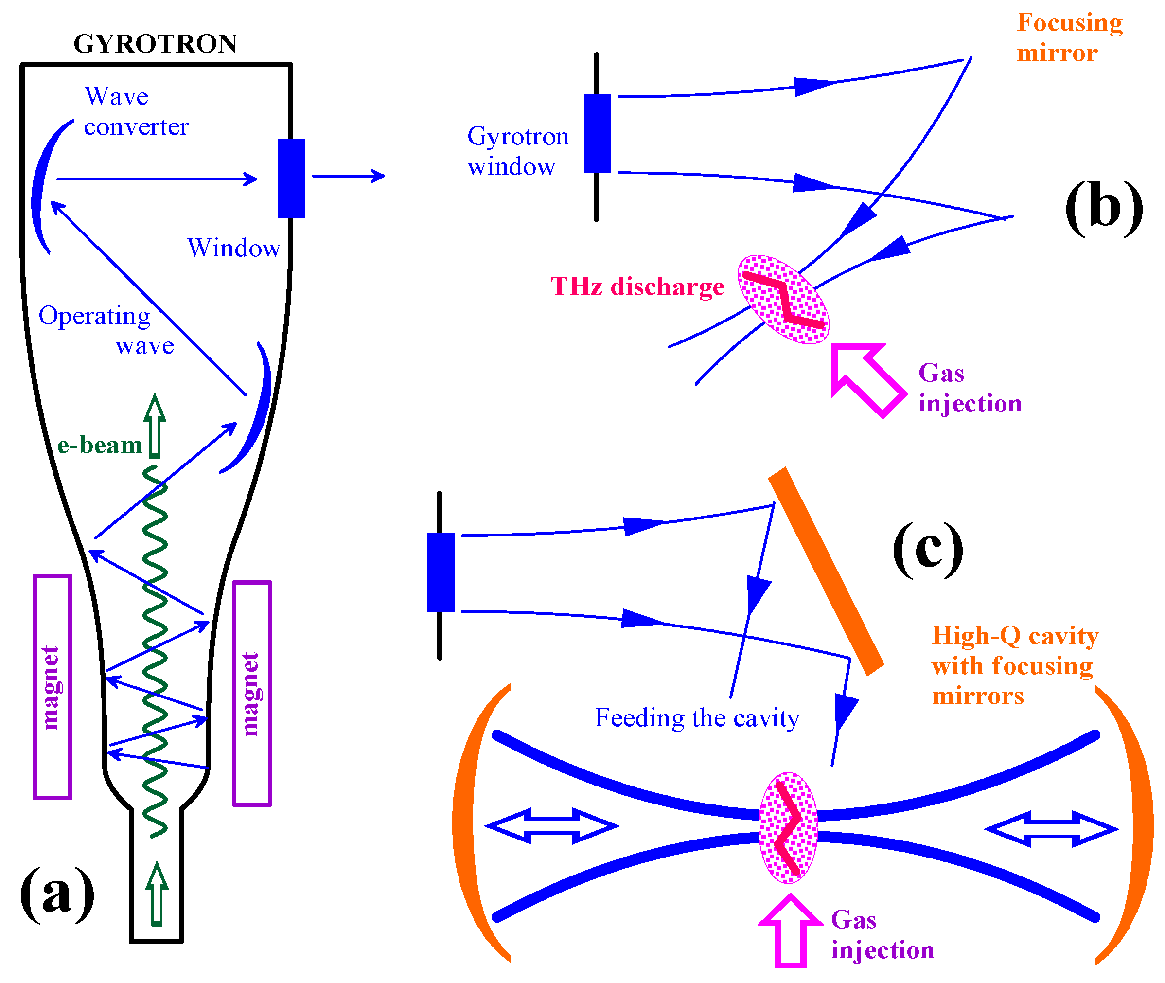
Figure 1. (a) Schematic of a gyrotron. (b) Direct focusing of the output gyrotron wave beam. (c) Focusing of the output wave beam accumulated inside a quasi-optical cavity.
Photonics 10 00440 g001
Figure 2. (a) Schematic of direct focusing of the gyrotron radiation (here, 1 is a quasi-optical converter of the operating gyrotron mode TE3,9 into a wave beam, 2 is a focusing mirror). (b) The calculated cross-section of the gyrotron wave beam (left) and the calculated distribution of the amplitude of the electric field (right). (c) The calculated cross-section of the wave beam in the focus point of the focusing mirror (left) and the calculated distribution of the amplitude electric field (right).
Photonics 10 00440 g002
Figure 3. Schematic of the cavity with the triangular trajectory of a traveling operating wave and a Bragg-type scattering photonic structure.
Photonics 10 00440 g003
Figure 4. Modeling of the wave field pattern using the ANSYS HFSS code when a plane wave falls at an angle of 60 0 on a corrugated surface with a corrugation period 0.83 λ.
Photonics 10 00440 g004
Figure 5. The reflection coefficients of the wave beam from a flat corrugated mirror with a corrugation period of 0.83 λ in the mirror (line 1) and (−1)-th (line 2) diffraction maxima depending on the amplitude of the sinusoidal corrugation.
Photonics 10 00440 g005
Figure 6. The power gain of the operating wave in the cavity versus the coupling coefficient of the operating wave with the external exciting wave.
Photonics 10 00440 g006
Figure 7. The scheme of the gyrotron radiation input into a quasi-optical cavity with a traveling wave. The stages of correction and the result of focusing the wave beam are shown. Here, 1 is the cross-section of the wave beam when falling on the first correction mirror (aperture 62 × 62 mm2), 2 is the cross-section of the wave beam when falling on the corrugated mirror of the cavity (aperture 62 × 62 mm2), and 3 is the cross-section of the wave beam at the aperture 5 × 5 mm2 between the focusing mirrors of the cavity.
Photonics 10 00440 g007
Figure 8. Calculated cross-section of the wave beam incident on the surface of the corrugated mirror of the cavity (a) and the calculated distributions of the amplitude of the electric field along the horizontal (b) and vertical (c) coordinates.
Photonics 10 00440 g008
Figure 9. Calculated cross-section of the wave beam in the focus of the focusing mirrors of the cavity (a) and the calculated distributions of the amplitude of the electric field along the horizontal (b) and vertical (c) coordinates.
Photonics 10 00440 g009
Figure 10. Growth of the amplitude of the electric field in the cavity during the first n periods of wave passage for a cavity with a Bragg-type photonic structure having a corrugation amplitude of A0 = 0.33 λ (a) and A0 = 0.17 λ (b).
Photonics 10 00440 g010
Table 1. Ohmic losses in mirrors of a cooper cavity.
σ (S/m) δ o h m , 1 2 δ o h m , 3 δ o h m
6   · 10 6 0.0070.0120.026
Table 2. Cavity parameters for two versions of the corrugation amplitudes.
MaterialCooper
δcom0.30.6
A00.17 λ0.33 λ
G9.94.2
Q146007600
Δf (MHz)68131
ΔL (mm)0.0160.03
Disclaimer/Publisher’s Note: The statements, opinions and data contained in all publications are solely those of the individual author(s) and contributor(s) and not of MDPI and/or the editor(s). MDPI and/or the editor(s) disclaim responsibility for any injury to people or property resulting from any ideas, methods, instructions or products referred to in the content.