Article

Infrared Gas Detection and Concentration Inversion Based on Dual-Temperature Background Points

1
Changchun Institute of Optics, Fine Mechanics and Physics, Chinese Academy of Sciences, Changchun 130033, China
2
University of Chinese Academy of Sciences, Beijing 100049, China
3
Chang Guang Satellite Technology Co., Ltd., Changchun 130102, China
4
Key Laboratory of Advanced Technology for Aerospace Vehicles of Liaoning Province, Dalian University of Technology, Dalian 116024, China
5
State Key Laboratory of Structural Analysis for Industrial Equipment, Dalian University of Technology, Dalian 116024, China
*
Authors to whom correspondence should be addressed.
Photonics 2023, 10(5), 490; https://doi.org/10.3390/photonics10050490
Submission received: 2 April 2023 / Revised: 21 April 2023 / Accepted: 21 April 2023 / Published: 24 April 2023
(This article belongs to the Special Issue Advanced Photonic Sensing and Measurement)

Abstract

:
Gas detection based on infrared thermal imaging is applied in many areas, but it is generally applied as a qualitative detection method to observe the target area; on the other hand, quantitative research on gas concentration is less common, the measurement accuracy is poor, and the calculation method of concentration in the commonly adopted transmission model is also complicated. In this paper, based on the radiance transfer model of gas infrared imaging technology, the influence of gas concentration, gas temperature, and background temperature on gas imaging detection is investigated, a gas detection and concentration inversion method based on dual-temperature background points is proposed, and the effects of the choice of reference band on background temperature correction are analyzed in relation to the changing trend of dual-band radiance difference. To verify the effectiveness of this method, a gas detection system with dual-temperature background spots was constructed in this paper utilizing a cooled mid-wave infrared focal plane detector plus a reference filter and a measurement filter, which achieved a promising concentration accuracy of less than 10% for carbon dioxide at a detectable range. Meanwhile, an infrared imaging system with a noise equivalent temperature difference (NETD) of 40 mK was employed to simulate the detection of methane, which enables the detection and concentration inversion of methane gas at a minimum concentration of 500 ppm·m at a distance of 1 km, which proves the capability of long-range detection.

1. Introduction

Gas infrared imaging detection technology has been identified as a powerful tool for industrial emissions, gas leakages [1,2,3,4], etc., as the method combines rapid measurement times, high sensitivity [5,6], and remote measurement capability with the identification of the gas being detected through the use of specific filters.
The most typically applied scenario for gas infrared thermal imaging systems is the visualization of gas emissions and hence a quick localization of leaks [7,8]. The representative products of gas detection include the GasFindIR [9] series gas imager of FLIR Systems and the Second Sight [10] series gas imager of the Bertin Technology company, as well as the handheld device EyeCGas2 for methane and volatile organic compounds (VOCs) leak detection by Opgal Company [11].
For quantitative calculation of target gas, scholars have mostly focused on calculating the gas velocity fields [12] via various estimation algorithms. Rangel J. et al. [13] proposed the on-scene flow rate computation of gas by using differential images from a stereo optical gas imaging (OGI) camera system and the corresponding experiment was evaluated. Abdel-Moati H. et al. [14,15] proposed a quantification OGI technique to quantify the mass leakage rate from captured video images by inputting the ambient temperature and the distance from the leakage point to the infrared camera, enabling a more accurate leakage calculation. Meanwhile, an approach to quantify methane gas flow rates by remote sensing was presented by Soren Dierks et al. [16]. The method is based on sensor data fusion of multiple sensors, involving a thermal camera for gas visualization and an active sensor based on tunable diode laser absorption spectroscopy (TDLAS).
However, there are relatively few reports on the quantification of target gas concentrations [17]. The gas imager Second Sight utilizes the infrared images obtained by reference and measurement filters and frame-to-frame differential algorithms to achieve the extraction of gas clouds and determination of concentration.
The detection of gas correlation imaging technique involves a calibration procedure used to perform concentration calculations. Sandsten J. et al. [18,19] proposed the gas correlation imaging technique which contains a gas correlation cell matching the absorption band of the gas; they achieved the imaging for ammonia with a detection limit of 200 ppm×m in the setup when the temperature difference between the background and the gas was 18. K. Kuijun Wu et al. [20] employed the gas correlation spectrometry-based mid-infrared camera in real-time imaging of CO in vehicle exhaust; a two-dimensional CO distribution of vehicle exhaust with a time resolution of 50 Hz and detection limit of 20 ppm×m was achieved when the distance between the optical equipment and engine nozzle was 3 m. However, there are few inversion methods for gas concentrations and no specific research or analysis is given for the issue of detection limits for common hazardous gases. Therefore, this paper aims to improve the accuracy of gas detection and the limits of detection by gaining an accurate understanding of the temperature difference between the background and the gas to be detected.
In this paper, firstly, the influencing factors of gas concentration inversion are analyzed according to the radiance transfer model, and the theoretical model is modified and simplified. Secondly, based on the modified radiance transfer model, a gas detection and concentration inversion method based on dual-temperature background points is proposed. Then, to verify the feasibility of the method, a gas detection system with dual-temperature background points is constructed. In addition, the detection of methane is simulated by employing an infrared imaging system with given parameters to demonstrate the capability of long-range detection.

2. Theory and Method

2.1. The Radiance Transfer Model

Gas infrared imaging technology utilizes the spectral absorption band properties of the target gas to monitor and identify the target detection gas in the atmosphere via a detector. In contrast to active infrared gas imaging, passive infrared gas imaging systems do not require an infrared light source and directly detect the spectral radiance of the target gas and the background. However, as the infrared spectrum is heavily influenced by the atmosphere or environment during the transmission from the target surface or background radiation to the detection system, a mathematical model is necessary to describe the radiation characteristics of infrared imaging. The layer radiance transfer model was first proposed by the U.S. Army Chemical Research Development and Engineering Center (CRDEC) [21] and is recognized and widely employed by researchers in gas passive infrared imaging detection techniques. The schematic diagram of the layer radiance transfer model is shown in Figure 1.
The model divides the path from the background scene to the sensors into a series of parallel layers, each of which includes the incoming radiance from the previous layer and the emitting radiance transmitted from this layer to the next. Thus, for a single layer in the model, such as layer i, the emitting radiance can be expressed as:
M i = ε T ε A ε I M i b + τ T τ A τ I M i 1 + ρ i
where M i b is the blackbody radiation of the ith layer at temperature T i ; M i 1 regards the output radiance of the previous layer; ε T , ε A and ε I are the emissivity of the target, atmosphere, and disturbance of the ith layer, respectively; the transmittance of the target, atmosphere, and interferents of the ith can be expressed as τ T , τ A and τ I ; ρ i denotes the scatter of all components in this layer, mainly representing the scattering from impurities such as aerosols.
In accordance with Kirchhoff’s law and an assumption of local thermodynamic equilibrium, the absorptance is equal to the emissivity, while the sum of absorptance and transmittance is 1; thus, ε + τ = 1 is obtained. Based on the assumption of neglecting the ambient radiation and the interference of aerosols and other impurities in the atmosphere, the layer transfer model can be simplified to the following equation as:
M i = 1 τ T 1 τ A M i b + τ T τ A M i 1
Assuming that the atmosphere is homogeneous in every single layer, and the looked-for gas occurs only in specific regions, the multiple-layer model can be simplified to a three-layer radiance transfer model as illustrated in Figure 2. Taking the gas cloud as demarcation, the whole transmission process can be divided into the background layer, the gas layer, and the atmospheric transmitting layer, which are noted as layers A, B, and C, respectively.
The common gas detection methods based on radiance transfer models are divided into gas path (on-plume path) and non-gas path (off-plume path) along the observation direction. The emitted radiance of each layer in the different path are noted as M i - O N and M i - O F F . According to the layer model mentioned above, the radiance transfer equations of each layer corresponding to the on-plume path can be derived as follows:
M A _ O N = τ A λ M B G λ , T b g + 1 τ A λ M A λ , T A
M B _ O N = τ g a s λ M A _ O N + 1 τ g a s λ M g a s λ , T g a s
M C _ O N = τ C λ M B _ O N + 1 τ C λ M C λ , T C
where τ i denotes the atmospheric transmittance of each layer; M B G λ , T b g denotes the spectral radiance of the background, which contains the radiance emitted by the background itself and the reflected radiance such as ambient radiance and radiance from the sky; however, most objects show low reflectivity on the surface, and thus the effect of background reflection is generally ignored. Assuming the emissivity of the background is ε b g λ , the background radiance can be expressed as:
M B G λ , T b g = ε b g λ M λ , T b g
The expression for the blackbody radiation of an object with temperature T is given by Planck’s formula as:
M λ , T = c 1 λ 5 1 exp c 2 / λ T 1
where the first radiation constant c 1 = 3.7418 × 10 8   W m 2 μ m 4 ; the second radiation constant c 2 = 1.4388 × 10 4   μ m K .
The radiance of the gas plume can be expressed as the blackbody radiation at T g a s , and the gas transmittance is written according to Beer–Lambert’s Law as:
τ g a s λ = exp α g a s λ 0 l c x d x
where α g a s λ is the absorption coefficient of the gas; the parameter of different gas types and states can be extracted from the HITRAN database [22]. c and l represent the concentration of the gas cloud and the length of the gas path along the detection direction, respectively.
Substituting Equations (4) and (5) into Equation (3) gets the radiance transmission equation from the background to the detecting system in the on-plume path. Parameters λ and T are hidden for the convenience of observation.
M C _ O N = τ C τ g a s τ A M B G + τ C τ g a s 1 τ A M A + τ C 1 τ g a s M g a s + 1 τ C M C
Similarly, the corresponding off-plume path can be expressed as:
M C _ O F F = τ C τ B τ A M B G + τ C τ B 1 τ A M A + τ C 1 τ B M B + 1 τ C M C

2.2. Simplified Layer Model

Under the common gas imaging detection scenarios, the lengths of Layer A and Layer B are very short compared to that of Layer C, so the atmospheric effects of Layer A and Layer B can be ignored, thus further simplifying the three-layer radiance transfer model to a two-layer radiance transfer model. The simplified two-layer transfer model can be expressed as:
M C _ O N = τ C τ g a s M B G + τ C 1 τ g a s M g a s + 1 τ C M C
M C _ O F F = τ C M B G + 1 τ C M C
Based on the spectral absorption characteristic curve of the target gas, there is a difference between the energy detected by the detector in the two path cases, which is given as:
Δ M = M C - O N M C - O F F = τ C 1 τ g a s M g a s M B G
From Equation (13), the inverse calculation of the target gas concentration can be expressed as:
1 τ g a s = M C _ O N M C _ O F F τ C M g a s M B G
By applying Equation (12), it is possible to eliminate M B G in Equation (13), which in turn simplifies to:
1 τ g a s = M C _ O N M C _ O F F τ C M g a s M C _ O F F + 1 τ C M C
Although variables M C _ O N and M C _ O F F are quantities that we can measure or estimate during the detection process, the gas radiance M g a s and path radiance M C that remain in Equation (15) add complexity to the gas concentration inversion.

2.3. Infrared Gas Detection and Concentration Inversion Method Based on Dual-Temperature Background Points

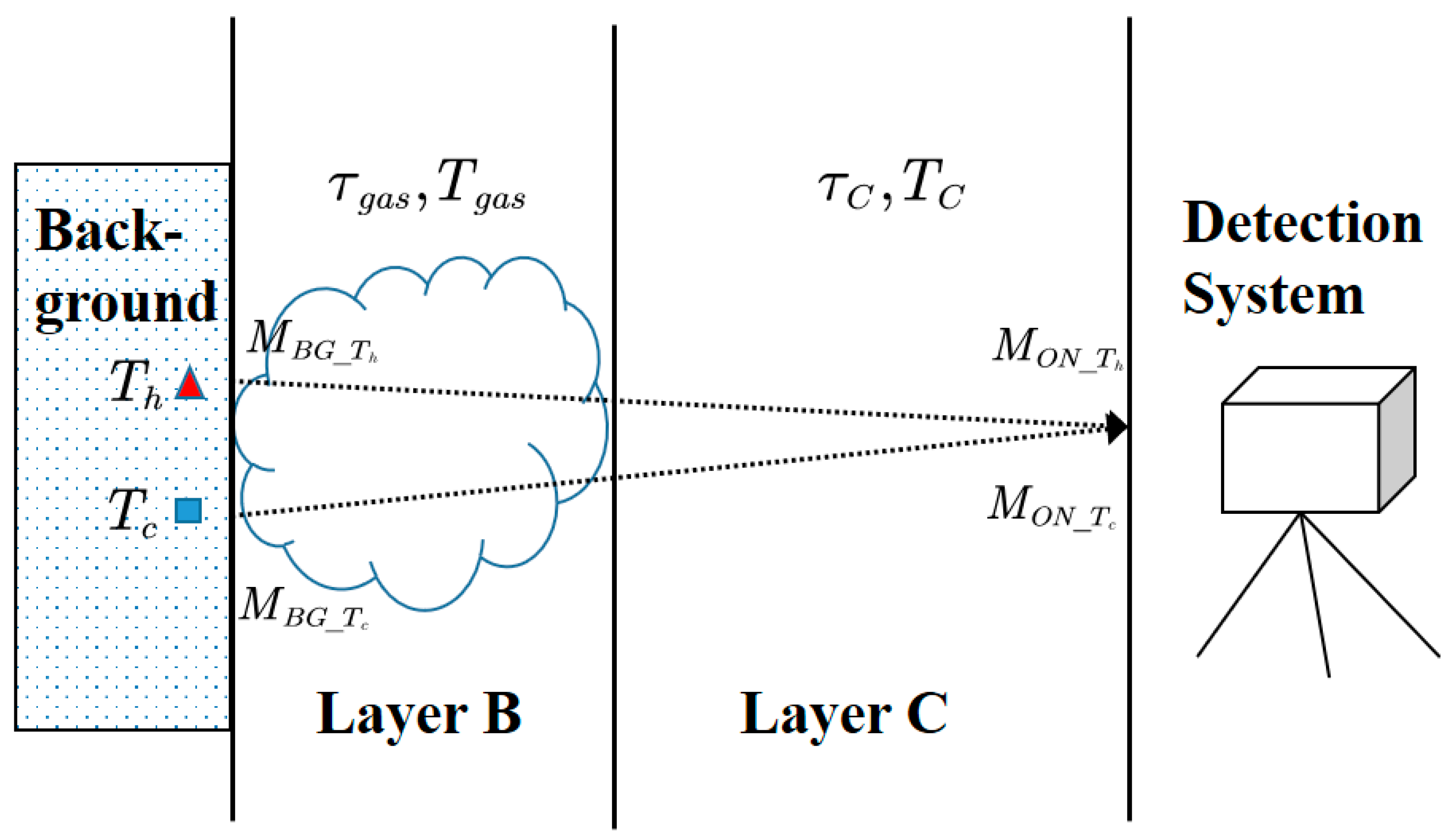
The method employed in this paper is established on the condition that there are two background spots with different temperatures on the gas path. It is assumed that two background points exist in the target gas region with temperatures of T h and T c , respectively, as presented in Figure 3, and the layer model described previously is utilized as the theoretical basis; thus, the radiance received by the imager can be expressed as:
M O N _ T h = τ C τ g a s M B G _ T h + τ C 1 τ g a s M g a s + 1 τ C M C
M O N _ T c = τ C τ g a s M B G _ T c + τ C 1 τ g a s M g a s + 1 τ C M C
When calculating the radiance variation from two background spots of different temperatures, the expression is independent of the radiance emitted from the gas cloud M g a s and from the path atmosphere M C , and only τ g a s , which is related to gas concentration, and the radiance difference of the two background points are retained, which is expressed as follows:
Δ M g a s _ O N = τ C τ g a s M B G T h M B G T c
In the case of the stable dual-temperature background points, the signal changes in the detecting region are clearly due to the presence/absence of gas, while the magnitude of the variation is directly related to the gas concentration, which in turn can be used for the concentration inversion of the looked-for gas cloud, expressed as:
c o n c e n t r a i o n Δ M g a s _ O N Δ M g a s _ O F F = λ _ m e a τ C τ g a s _ o n M B G T h M B G T c λ _ m e a τ C M B G T h M B G T c
Based on Beer–Lambert’s law, the relationship between the variation of τ g a s with the concentration integrated along the path length is obtained from Equation (8), so as to perform concentration inversion.
When in the actual process of implementation, the temperatures of the two background points selected are not stable values, the background spot radiance energy difference term in Equation (18) needs to introduce a means of correction. In this paper, the detection process uses dual-band data acquisition of the target point, and then calculates the radiation energy variation of the reference band, so as to achieve the calibration of the radiance difference of the actual background points in the measurement band.
The output voltage of the detector is the value related to the incident radiation flux and the detector responsivity, which is expressed as:
V s = Φ λ R λ
where responsivity is denoted as R λ = D λ A d Δ f 1 / 2 , and D λ , A d , and Δ f represent the normalized detectivity, photosensitive area, and the bandwidth of the measurement circuit, respectively. For an ideal thermal detector, D λ is independent of λ , which means D λ = D 0 .
In addition, based on the radiance transfer model and the image plane illuminance calculation formula of the imaging system, the radiation flux incident to the center of the detector image is denoted as:
Φ λ = E λ A d = τ o A d M λ , T 4 F / # 2
which is related to the radiance entering the imaging system, together with system parameters such as F number, the optical transmittance τ o , etc.
Thus, for a specific infrared imaging system, the output signal can be expressed as:
V s = D 0 τ o A d 4 F / # 2 A d Δ f λ 1 λ 2 M λ , T d λ
where the parameters in front of the integral equation are quantities relevant to the system itself and can be considered as constant.
Consequently, with the above assumptions, the conversion process from optical to electrical signal completed by the detector can be simplified in the formula, which is expressed as the multiplication of the radiation flux on the image plane and the responsivity R v .
As for infrared gas imaging detection, in order to distinguish the presence of the target gas cloud in the observation region the system is required to be capable of recognizing the difference in signal generated between the condition with or without the gas plume. By applying the performance parameter NETD of the infrared imaging system, the minimum resolvable variation in output voltage for conditions T 1 = T t e s t + N E T D and T 2 = T t e s t is given by the following equation:
Δ V s = R v λ 1 λ 2 M λ , T 1 d λ λ 1 λ 2 M λ , T 2 d λ
The conversion process from optical to electrical signal completed by the detector is simplified in the formula, which is expressed as the multiplication of the radiation flux on the image plane and the responsivity R v . When the difference of the signal generated by the appearance of the target gas is equal to this value, the minimum resolvable gas concentration of the system is derived.

3. Discussion and Details

3.1. Limitation of Critical Temperature in Traditional Method

The effects of gas concentration, gas temperature, and background temperature on gas detection imaging detection systems are further investigated. It can be seen from the term M g a s M B G in Equation (13), regardless of whether the background ( ε b g = 1 ) is blackbody or graybody ( ε b g < 1 ), that there always exists a certain value for gas temperature T g a s _ c r i t i c a l that makes M g a s M B G = 0 , which means that however the gas concentration or path length varies, it gets Δ M = 0 .
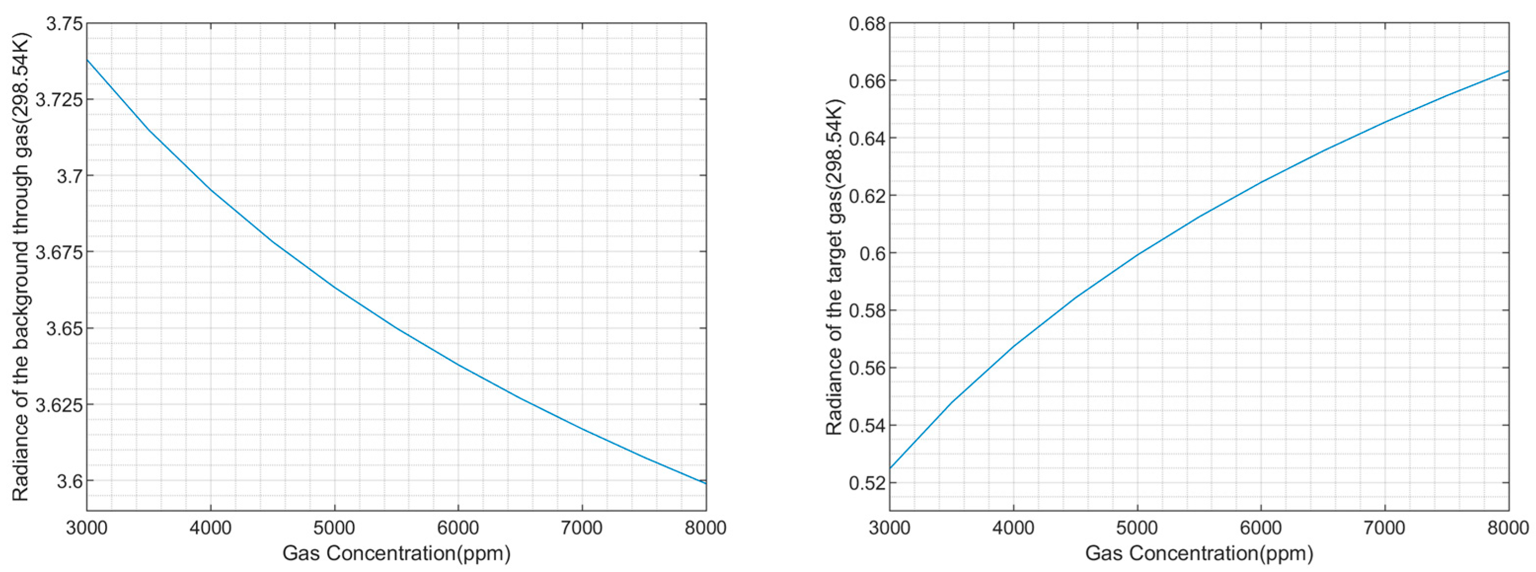
The physical essence of the described statement above is that, due to the appearance of the target gas cloud, the total radiance of the on-plume path can be divided into two parts: one is the radiance of the background through gas, while the other is the radiance of the gas itself (without considering the path radiance). In the case of constant gas and background temperatures, with the increase of gas concentration the radiance of the background through the gas decreases while the radiance of gas itself increases, but the magnitude of variation between the two is different, which leads to Δ M 0 .
The change of the gas temperature T g a s introduces another part of the radiation increment, which affects the radiance of gas itself M g a s λ , T g a s but does not affect the transmittance spectrum (with the help of the HITRAN database, the relative variation of transmittance spectra in the 3~5 μm band was calculated to be about 0.03% for the standard case of 296 K and the given case of 326 K). In other words, the radiance of the background through the gas plume remains stable when the gas temperature varies.
Thus, there exists a critical value of gas temperature T g a s _ c r i t i c a l which makes the increase and decrease of radiance described above compensate for each other in that case. By this time, M C _ O N = τ C τ g a s M B G + τ C 1 τ g a s M g a s , the sum of the radiance of the on-plume path, is equal to that of the off-plume path, M C _ O F F = τ C M B G , demonstrated in other words as Δ M = 0 .
Assuming that the background is a graybody, the emissivity ε b g = 0.95 , the background temperature T b g = 300   K , and the waveband chosen is 4~5 μm, the critical temperature under these conditions is calculated as T g a s _ c r i t i c a l = 298.54   K . The following Figure 4 illustrates the curves of the radiance of the background through gas, the radiance of the target gas itself (related in Equation (11)) varying with the gas concentration, respectively, while the gas is at the critical temperature.
From Figure 5, it can be observed that the difference in radiance between the gas and the off-gas path decreases with increasing gas concentration when the gas temperature is at an arbitrarily picked 295 K, while the corresponding value of the critical gas temperature is nearly invariant, and the deviation of its vertical coordinate is of the level of 10 3 , which indicates the undetectable gas in this situation.

3.2. Selection of Reference and Measurement Band

For the detection system, the output of the detector is determined by the incident radiation flux in conjunction with its spectral response. The selection of an appropriate band range for the reference and measurement filters can take full advantage of the gas infrared radiation and absorption properties, so this section will conduct analytical work on the selection of the two bands.
Since the gas detection is accomplished through the absorption properties of the gas, the range selected for the measurement band is required to cover the absorption peaks of the target gas, while the spectral transmission of the reference band is located outside the absorption features to characterize the background scene and for the correction of changes in radiance differences between the dual-temperature background spots.
For this reason, it is necessary to analyze the consistency and correlation coefficients of the relationship of the corresponding radiance difference changes between the reference and measurement bands under the condition of single background point temperature variation due to its characteristic or simultaneous temperature shift of two spots caused by environmental factors.
Here, carbon dioxide is employed as the looked-for gas; it has a strong absorption peak at 4.23~4.28 μm, and the measurement band is chosen as 4~4.5 μm in consideration of the available filters, while for the reference band several different band ranges are selected for discussion.
Straightforwardly, the consistency of the variation tendency of the radiation of the two bands is obviously known from Wien’s displacement law Equation (24). For the blackbody with a temperature not higher than 579.54 K, the peak wavelength of its radiation spectrum is greater than 5 μm, so for the reference and measurement bands selected in the mid-wave infrared band it can have a consistent trend when the temperature of the background changes.
λ max = b T
where b is the Wien’s displacement constant b = 2.897771955 × 10 3   m K .
Meanwhile, due to the requirement of utilizing the reference band detection value for the correction of the radiance variation at the background point of the measurement band, here the radiance difference variation curve (shown in Figure 6) of the calibration value of the reference bands and the theoretical value of the measurement band are given under the circumstances of the different backgrounds T h and T c , as well as the temperature difference Δ T = T h T c .
The results in Figure 6 simply use the first-order linear relationship to fit the corresponding values of the measurement band; it can be indicated that despite the increased deviation near the end of the curve, the three chosen reference bands effectively completed the correction for the background radiance at the measurement band. As for the 4~4.2 μm reference channel, whose band selection is based on subtracting the absorption peak of the target gas from the measurement band, its overall radiance difference variation is in high coherency with the measurement band of 4~4.5 μm. Although for the other 3.5~3.9 μm and 4.5~5 μm channels the correction results are slightly worse than those of 4~4.2 μm, the two as reference bands can still meet the accuracy requirements. To further improve the fitting accuracy, the number of polynomial orders can be increased to the second order.
The Frechet-Distance is one of the criterions to evaluate the similarity of trajectory sequences. It is used in this paper to describe the deviation of radiance difference between the calibration value and the theoretical value under different circumstances. The results describing the similarity between the two curves by Frechet-Distance are shown in Table 1.

3.3. Calculation of Target Gas Concentration Using MODTRAN

The gas concentration inversion process could be conducted once the looked-for gas region is determined. Assuming that the detector observes the target background region along a horizontal path, by utilizing MODTRAN, a software for calculating moderate spectral resolution atmospheric transmittance, the gas concentration calculation process is as follows:
Step 1. Based on the trend of the background radiance difference in the reference band, the correction coefficient to the measurement band is introduced.
Step 2. By assuming the initial value of the target gas concentration p p m m i n i t i a l , the gas spectral transmittance under these parameters is calculated using MODTRAN.
Step 3. The theoretical R a t i o i is calculated from the difference between the obtained gas spectral transmittance and the radiance difference of the background points collected by the detection system.
Step 4. Whether the difference value meets the requirement of precision e is evaluated. If it is less than the given precision, the gas concentration value at this time is taken as the output of the calculation result; otherwise, a new target gas concentration is set based on the difference value, and the calculation process is returned to step 2 as presented in Figure 7.

4. Experiments and Analysis

4.1. Verification Experiments and Result Analysis of CO2 Imaging Detection

CO2 imaging detection experiments were conducted in the laboratory using a mid-wave infrared focal plane detector, and the switch of different bands was realized by a filter wheel between the lens and detector, which enables the acquisition of infrared images in different wavelength. The common gas imaging detection method based on the layer radiance transfer model requires a difference between the target gas and background temperature, which was analyzed in the previous section. Therefore, for experimental operability considerations, a blackbody radiator was used as the background to avoid the situation of critical temperature. In addition, to reduce the diffusion of CO2 during the experiment, a simple gas cell made of mid-wave IR window glass (illustrated in Figure 8) was used and filled with CO2 gas of a known concentration during imaging detection.
Experiment setup: The temperature of the blackbody was set to 50 °C and was placed as near as possible to the center of the imaging region. The concentration of human breath measured by the handheld carbon dioxide concentration detector was about 9000 ppm; the camera exposure time was set to 15 ms and the initial filter was selected to be in the 2.8~5.2 μm band.
The experiment procedures are as follows:
  • Activate the cooled mid-wave infrared detector and wait until the operating temperature is reached, with the blackbody temperature set at 50 °C.
  • The detector acquires three images as background images after the blackbody temperature is stabilized.
  • The detector collects images when a human exhales carbon dioxide in front of the blackbody background.
  • Adjust the filter wheel and choose filters with bands of 4~4.5 μm and 4.5~5 μm in turn and repeat steps 2 to 3.
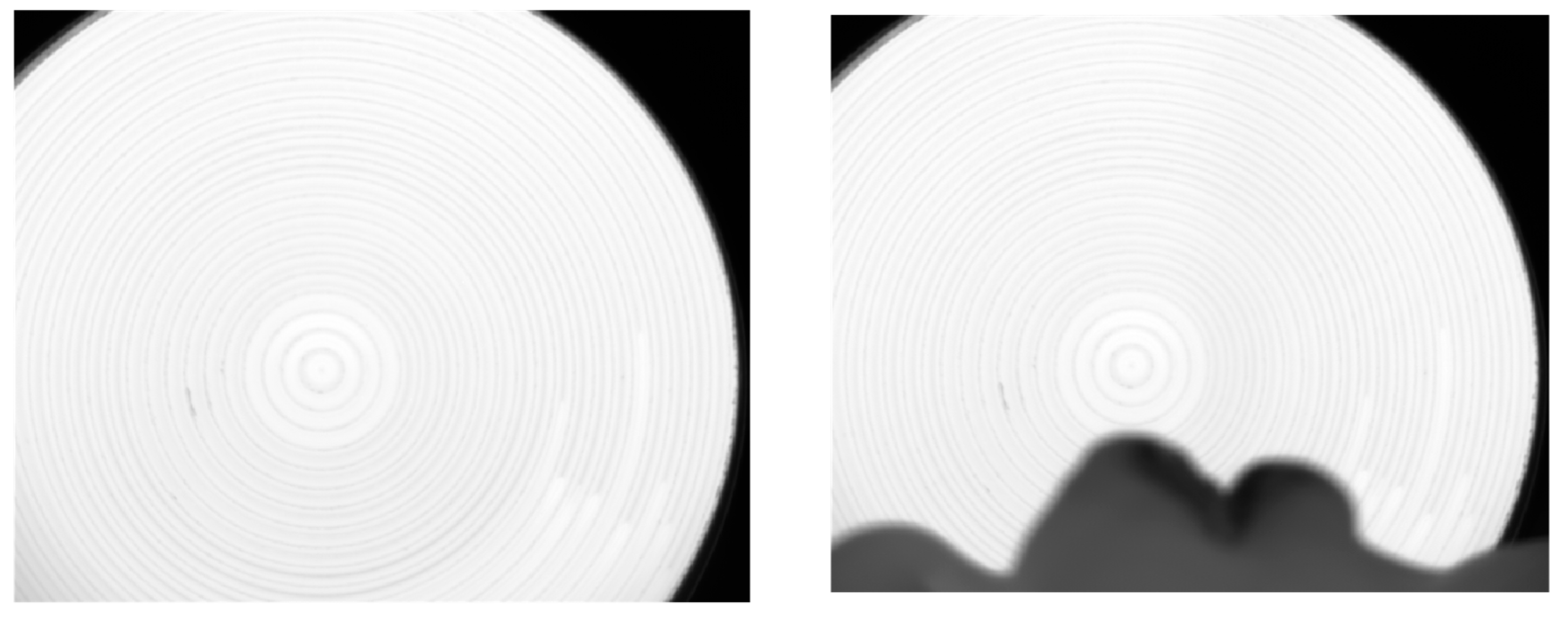
For data processing, the three background images acquired were averaged and the variation map of grayscale was obtained by differencing the background average image from the exhale image of the corresponding band shown in Figure 9, respectively.
The results of the grayscale changes obtained by image differencing are illustrated in Figure 10, which shows that for the 2.8~5.2 μm and 4~4.5 μm bands, due to the presence of the absorption peak of CO2 in the band selected, the change of grayscale caused by human exhaled CO2 gas can be observed, while for 4.5~5 μm there is no obvious phenomenon. The experiment demonstrates the necessity of the measurement band containing the gas absorption peak, as well as the feasibility of the infrared gas imaging detection method.

4.2. Experiment and Result Analysis of Gas Detection Method Based on Dual-Temperature Background Points

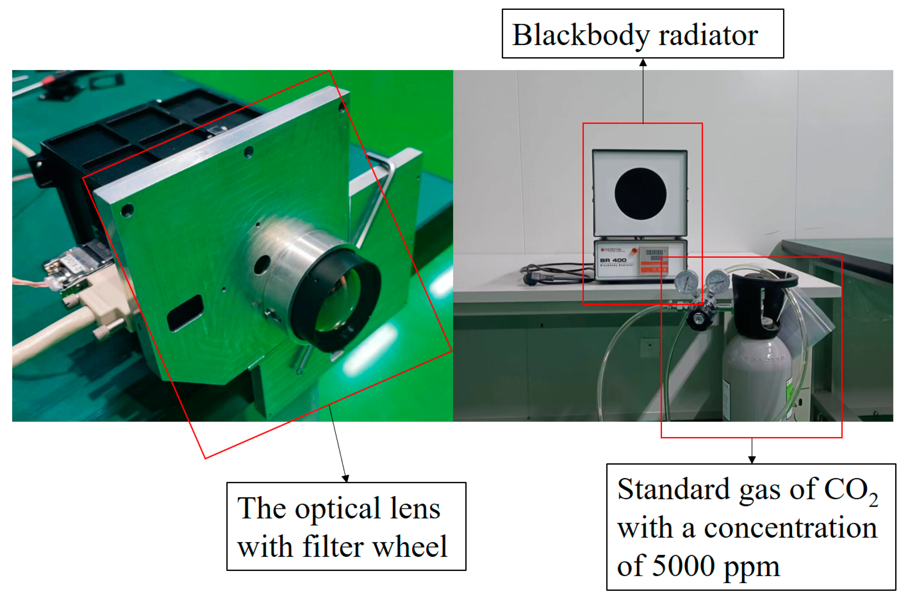
In the laboratory, the Optris BR 400 blackbody radiator was employed at different temperatures separately to perform as the dual-temperature background on the gas path; the distance between the infrared system and the blackbody background was set to 20 m. The target gas was a standard gas of carbon dioxide at 5000 ppm stored in a compressed gas cylinder which was depressurized by the decompression device and released under the control of a gas-flow meter. The blackbody was placed in the center of the imaging area; the change of the reference and measurement bands was achieved by the filter wheel in front of the detector. The experimental equipment mentioned above could be seen in Figure 11.
The experimental procedures are as follows:
  • Activate the cooled mid-wave infrared detector and allow it to stabilize at the operating temperature with the blackbody temperature set at 40 °C and 50 °C in turn.
  • The detector acquires the background images of the reference and measurement bands without the target gas and for each condition collects three images.
  • Release the carbon dioxide standard gas and ensure that the target gas region covered contains the background. The detector collects the corresponding on-gas images of the reference and measurement bands.
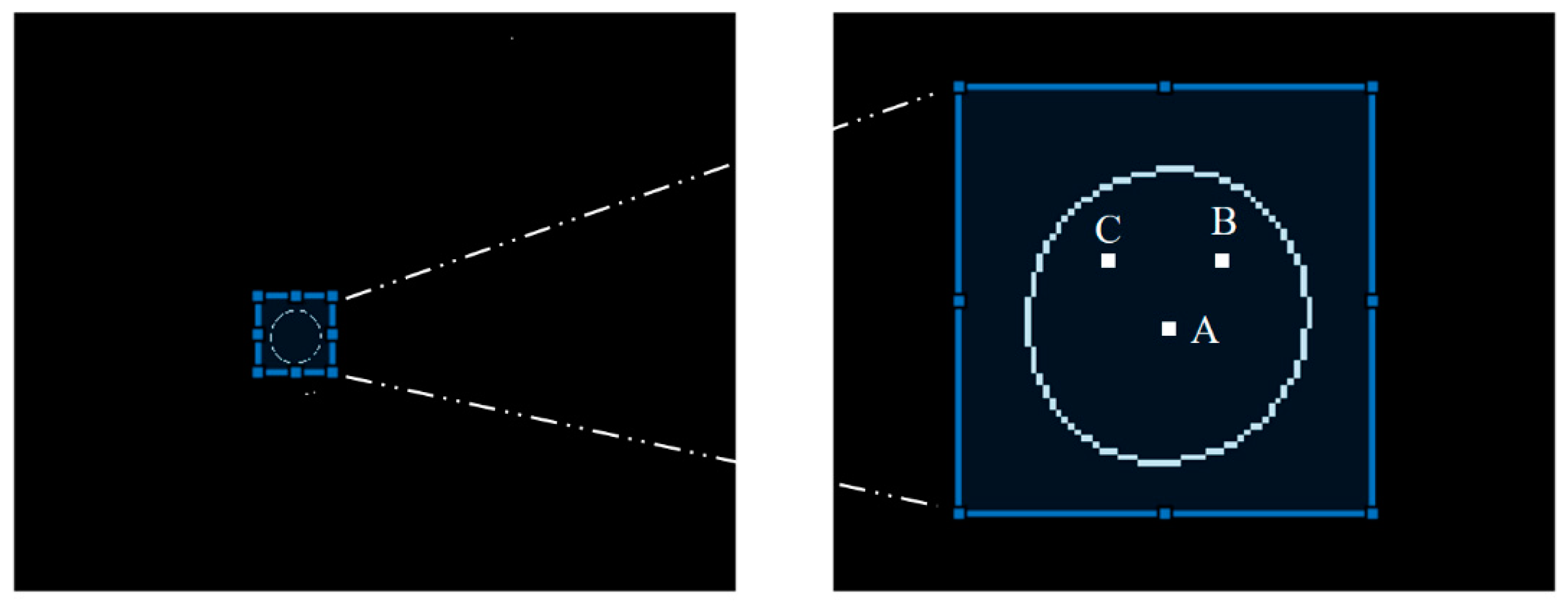
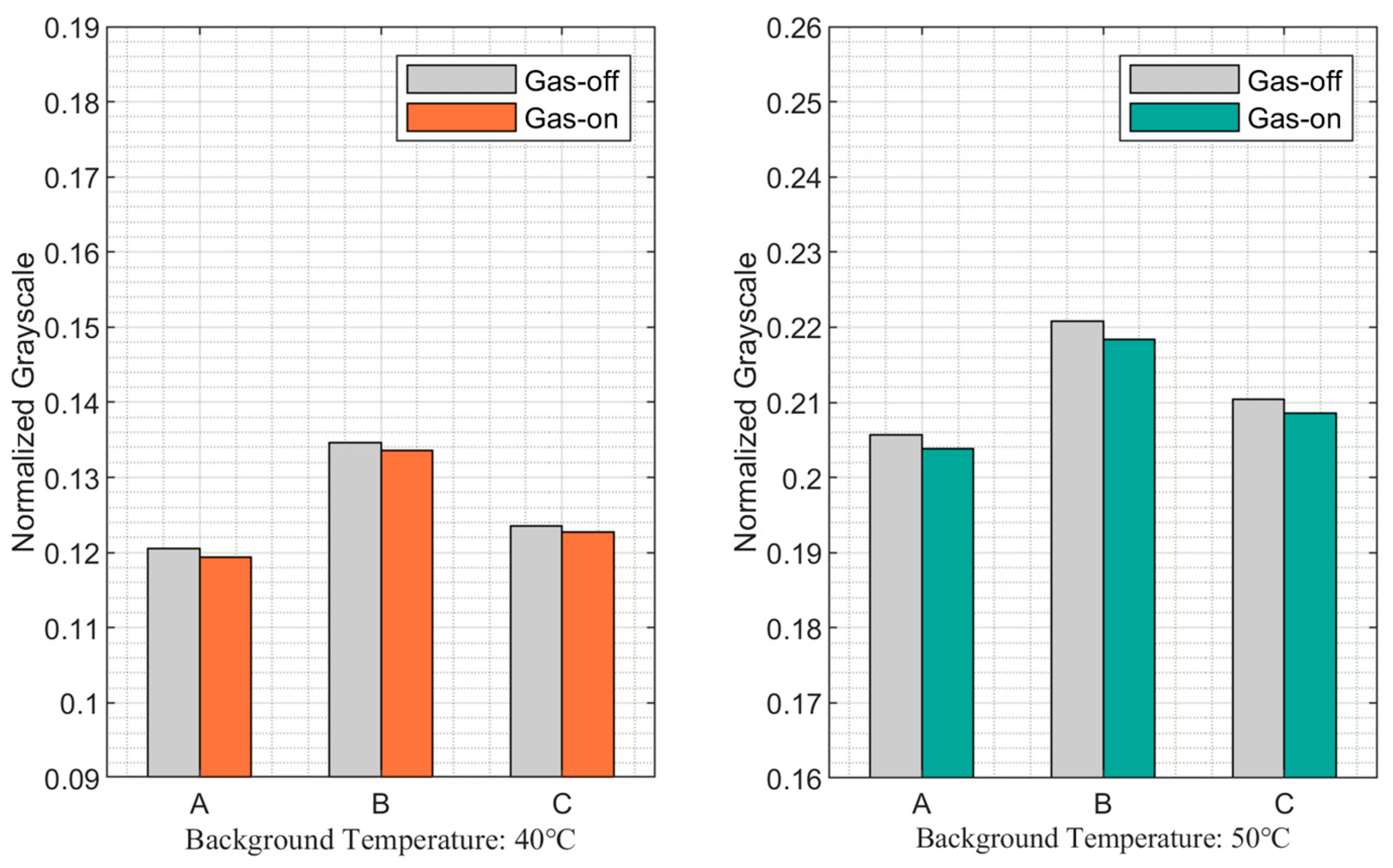
The blackbody radiator had an aperture of 128 mm, and the blackbody background was selected from the images by the edge extraction algorithm. And a total of three data points were picked from the center, as well as from the upper right and upper left within the aperture area, denoted as A, B and C respectively, as shown in the following Figure 12. The normalized grayscale values of the dual-temperature background in different gas situations collected by the detectors are plotted in Figure 13 and Figure 14.
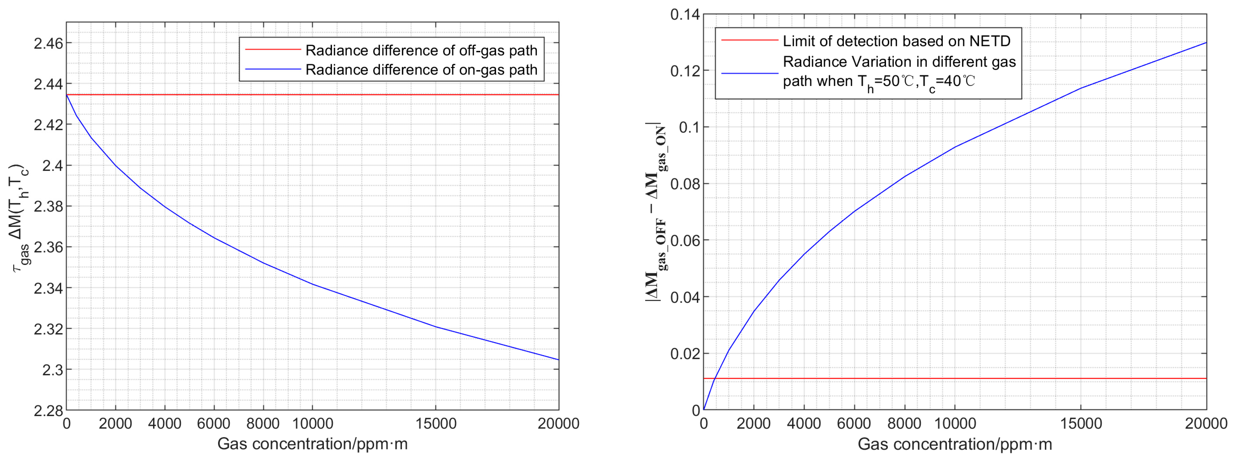
Under the condition that the dual-temperature points are set to 40 °C and 50 °C, respectively, with the gas path length of 1 m, the theoretical calculations of the radiance difference of the measurement band in the on-gas and off-gas path varying with the target CO2 gas concentration are given in Figure 15.
As seen from the data in the measurement band, the transmittance decreases with increasing CO2 concentration under the situation that the gas path length remains constant, which leads to the decrease of the radiance difference of the double background point through gas, as illustrated in Figure 15.
Furthermore, the data processing results of the two bands calculated from the normalized grayscale of background spots collected under on-gas and off-gas path conditions are shown in Table 2 below.
According to the simulation and experimental results, for the reference band, the radiance difference of the background can be considered as showing no significant or abrupt change in the background temperature; therefore, there is no need to make further corrections for the measurement band, which is consistent with the theoretical analysis of the reference band as well as the experimental setup.
Furthermore, the variation of the radiance difference of the dual-temperature background in the measured band indicates changes in transmittance due to the presence of CO2 gas, expressed as
λ _ m e a τ a t m Δ M B G T h , T c λ _ m e a τ a t m τ g a s Δ M B G T h , T c
Based on the ratio of the difference in radiance between the two background spots of the gas path and the off-gas path, the target gas concentration is estimated to be around 4650 ppm, which is within 10% relative error of the theoretical value. Considering the flow and dispersion of the gas plume in the actual experimental situation, it can be considered that the retrieving concentration from the experimental results is highly accurate.
When CO2 is applied as the target gas, the absorption of CO2 is easily saturated at the atmospheric concentration path length due to its spectral line intensity at 2349 c m 1 , which means the gas transmittance has dropped to zero and will cause the newly emerged high concentration CO2 gas cloud in the path to be undetectable, thus limiting the detection distance.
Therefore, in this paper, simulation work was carried out for methane application scenarios: the minimum resolvable gas concentration at a 1 km detection distance was calculated for an infrared system with an NETD of 40 mK at dual-temperature background points of 30 °C and 20 °C, together with 50 °C and 40 °C, respectively, and the measured value-concentration relationship curve for inversion is given.
The simulation utilizes the infrared absorption of methane located at 3.31 μm. The 2750~3250 c m 1 measurement band was selected and the methane gas path length was taken as 1 m, with the methane atmospheric concentration taken as 2000 ppb based on the National Oceanic and Atmospheric Administration (NOAA) dataset gallery [23]. The methane alarm concentration was set at the common low explosion level of 1.25% Vol, which is 12,500 ppm. For the infrared system given in this paper, the corresponding minimum resolvable radiance difference was calculated based on the Equation (23) described above, and the result is shown in Table 3. Thus, the simulation results demonstrate that the gas detection and concentration inversion method could achieve the minimum resolvable gas concentration of 500 ppm·m and 250 ppm·m at a distance of 1 km under the respective conditions. The correlated results are underlined in Table 4.

5. Conclusions

In this paper, a detection method of infrared gas imaging which achieves the detection of gas concentration quantification with good measurement accuracy was proposed. By calculating the radiance difference between the two-temperature background points, the method eliminates the gas radiance and path radiance, which increases the complexity of the concentration inversion in the conventional method and obtains a value related to the gas concentration and the background radiance difference. Possible interferences caused by background temperature variations can be resolved using an additional reference band. Experiments with a mid-wave infrared imaging system and filters of different wavelengths for CO2 have verified the correctness and validity of our method. Simulation work on methane application scenarios demonstrates the capability of long-range detection. There is considerable space for research to improve the inversion accuracy of gas concentrations in complex backgrounds, and this study lays the foundation for subsequent work.

Author Contributions

Conceptualization, S.W. and X.Z.; methodology, S.W. and X.Z. and Z.Q.; software, S.W.; validation, S.W., X.Z. and Z.Q.; formal analysis, Y.W. and L.L.; investigation, C.Z.; writing—original draft preparation, S.W., X.Z. and Z.Q.; writing—review and editing, Y.W., L.L. and C.Z.; supervision, X.Z.; funding acquisition, X.Z. All authors have read and agreed to the published version of the manuscript.

Funding

This research was funded by the National Key Research and Development Program of China, grant number 2019YFE0127000.

Institutional Review Board Statement

Not applicable.

Informed Consent Statement

Not applicable.

Data Availability Statement

Data is contained within the article.

Conflicts of Interest

The authors declare no conflict of interest.

References

  1. Meribout, M. Gas Leak-Detection and Measurement Systems: Prospects and Future Trends. IEEE Trans. Instrum. Meas. 2021, 70, 4505813. [Google Scholar] [CrossRef]
  2. Lu, H.; Iseley, T.; Behbahani, S.; Fu, L. Leakage Detection Techniques for Oil and Gas Pipelines: State-of-the-Art. Tunn. Undergr. Space Technol. 2020, 98, 103249. [Google Scholar] [CrossRef]
  3. Meribout, M.; Khezzar, L.; Azzi, A.; Ghendour, N. Leak Detection Systems in Oil and Gas Fields: Present Trends and Future Prospects. Flow Meas. Instrum. 2020, 75, 101772. [Google Scholar] [CrossRef]
  4. Xiong, K.; Jiang, J.; Pan, Y.; Yang, Y.; Chen, X.; Yu, Z. Deep Learning Approach for Detection of Underground Natural Gas Micro-Leakage Using Infrared Thermal Images. Sensors 2022, 22, 5322. [Google Scholar] [CrossRef] [PubMed]
  5. Zhang, Z.; Zhang, F.; Xu, B.; Xie, H.; Fu, B.; Lu, X.; Zhang, N.; Yu, S.; Yao, J.; Cheng, Y.; et al. High-Sensitivity Gas Detection with Air-Lasing-Assisted Coherent Raman Spectroscopy. Ultrafast Sci. 2022, 2022, 9761458. [Google Scholar] [CrossRef]
  6. Liu, X.; Qiao, S.; Han, G.; Liang, J.; Ma, Y. Highly Sensitive HF Detection Based on Absorption Enhanced Light-Induced Thermoelastic Spectroscopy with a Quartz Tuning Fork of Receive and Shallow Neural Network Fitting. Photoacoustics 2022, 28, 100422. [Google Scholar] [CrossRef] [PubMed]
  7. Zhao, Q.; Nie, X.; Luo, D.; Wang, J.; Li, Q.; Chen, W. An Effective Method for Gas-Leak Area Detection and Gas Identification with Mid-Infrared Image. Photonics 2022, 9, 992. [Google Scholar] [CrossRef]
  8. Murvay, P.-S.; Silea, I. A Survey on Gas Leak Detection and Localization Techniques. J. Loss Prev. Process Ind. 2012, 25, 966–973. [Google Scholar] [CrossRef]
  9. Mammen, C.H.; Benson, R.G. Thermography Camera Configured for Gas Leak Detection. Patent 7649174, 19 January 2010. Available online: https://www.freepatentsonline.com/7649174.html (accessed on 2 March 2023).
  10. Naranjo, E.; Baliga, S.; Bernascolle, P. IR Gas Imaging in an Industrial Setting. In Thermosense XXXII; SPIE: Orlando, FL, USA, 2010; Volume 7661, pp. 160–167. [Google Scholar] [CrossRef]
  11. Hashmonay, R.; Yanai, O. Methods for Classification of a Gas Compound in a Gas Leak. Patent 20210102840, 8 April 2021. Available online: https://www.freepatentsonline.com/y2021/0102840.html (accessed on 2 March 2023).
  12. Shiozawa, D.; Uchida, M.; Ogawa, Y.; Sakagami, T.; Kubo, S. Four-Dimensional Reconstruction of Leaked Gas Cloud Based on Computed Tomography Processing of Multiple Optical Paths Infrared Measurement. Eng. Proc. 2021, 8, 33. [Google Scholar] [CrossRef]
  13. Rangel, J.; Schmoll, R.; Kroll, A. On Scene Flow Computation of Gas Structures with Optical Gas Imaging Cameras. In Proceedings of the 2020 IEEE Winter Conference on Applications of Computer Vision (WACV), Snowmass Village, CO, USA, 1–5 March 2020; pp. 174–182. [Google Scholar] [CrossRef]
  14. Abdel-Moati, H.; Morris, J.; Zeng, Y.; Kangas, P.; McGregor, D. New Optical Gas Imaging Technology for Quantifying Fugitive Emission Rates. In Proceedings of the IPTC International Petroleum Technology Conference, Doha, Qatar, 6–8 December 2015. [Google Scholar] [CrossRef]
  15. Zeng, Y.; Morris, J.; Sanders, A.; Mutyala, S.; Zeng, C. Methods to Determine Response Factors for Infrared Gas Imagers Used as Quantitative Measurement Devices. J. Air Waste Manag. Assoc. 2017, 67, 1180–1191. [Google Scholar] [CrossRef] [PubMed]
  16. Dierks, S.; Kroll, A. Quantification of Methane Gas Leakages Using Remote Sensing and Sensor Data Fusion. In Proceedings of the 2017 IEEE Sensors Applications Symposium (SAS), Glassboro, NJ, USA, 13–15 March 2017; pp. 1–6. [Google Scholar] [CrossRef]
  17. Kang, R.; Liatsis, P.; Kyritsis, D.C. Emission Quantification via Passive Infrared Optical Gas Imaging: A Review. Energies 2022, 15, 3304. [Google Scholar] [CrossRef]
  18. Sandsten, J.; Edner, H.; Svanberg, S. Gas Imaging by Infrared Gas-Correlation Spectrometry. Opt. Lett. 1996, 21, 1945–1947. [Google Scholar] [CrossRef] [PubMed]
  19. Sandsten, J.; Weibring, P.; Edner, H.; Svanberg, S. Real-Time Gas-Correlation Imaging Employing Thermal Background Radiation. Opt. Express 2000, 6, 92–103. [Google Scholar] [CrossRef] [PubMed]
  20. Wu, K.; Feng, Y.; Yu, G.; Liu, L.; Li, J.; Xiong, Y.; Li, F. Development of an Imaging Gas Correlation Spectrometry Based Mid-Infrared Camera for Two-Dimensional Mapping of CO in Vehicle Exhausts. Opt. Express 2018, 26, 8239–8251. [Google Scholar] [CrossRef] [PubMed]
  21. Flanigan, D.F. Limits of Passive Remote Detection of Hazardous Vapors by Computer Simulation. In Electro-Optical Technology for Remote Chemical Detection and Identification; Fallahi, M., Howden, E.A., Eds.; SPIE: Orlando, FL, USA, 1996; Volume 2763, pp. 117–127. [Google Scholar] [CrossRef]
  22. Gordon, I.E.; Rothman, L.S.; Hargreaves, R.J.; Hashemi, R.; Karlovets, E.V.; Skinner, F.M.; Conway, E.K.; Hill, C.; Kochanov, R.V.; Tan, Y.; et al. The HITRAN2020 Molecular Spectroscopic Database. J. Quant. Spectrosc. Radiat. Transf. 2022, 277, 107949. [Google Scholar] [CrossRef]
  23. Greenhouse Gas Concentrations—Graphing Tool | NOAA Climate.gov. Available online: http://www.climate.gov/maps-data/dataset/greenhouse-gas-concentrations-graphing-tool (accessed on 26 March 2023).
Figure 1. The schematic diagram of the layer radiance transfer model.
Photonics 10 00490 g001
Figure 2. The schematic diagram of the three-layer radiance transfer model.
Photonics 10 00490 g002
Figure 3. Schematic diagram of the dual-temperature background points radiance transfer model.
Photonics 10 00490 g003
Figure 4. Variation of the radiance of the background through the gas (left) and the radiance of the target gas itself (right) with the concentration of the target gas ( T g a s _ c r i t i c a l = 298.54   K ).
Photonics 10 00490 g004
Figure 5. Curves of radiance difference between gas path and non-gas path with target gas concentration for the gas temperature of 295 K (left) and gas temperature of critical temperature 298.54 K (right).
Photonics 10 00490 g005
Figure 6. The variation curves of the radiance difference of the corrected value for the selected reference band and the theoretical value for the measured band under different temperature conditions.
Photonics 10 00490 g006
Figure 7. The calculation procedure of concentration inversion.
Photonics 10 00490 g007
Figure 8. Mid-wave infrared window glass gas chamber.
Photonics 10 00490 g008
Figure 9. Background average image (left) and human exhalation image (right).
Photonics 10 00490 g009
Figure 10. Changes in grayscale in each band obtained from the differential of corresponding background and exhalation image (left) 2.8~5.2 μm, (middle) 4~4.5 μm, (right) 4.5~5 μm).
Photonics 10 00490 g010
Figure 11. Cooled mid-wave infrared detector with filter wheel (left), blackbody radiation source with CO2 gas cylinder (right).
Photonics 10 00490 g011
Figure 12. The edge extraction result for blackbody (left) and the schematic diagram of three selected points (right).
Photonics 10 00490 g012
Figure 13. Normalized grayscale of reference band in on-gas/off-gas path.
Photonics 10 00490 g013
Figure 14. Normalized grayscale of measurement band in on-gas/off-gas path.
Photonics 10 00490 g014
Figure 15. The theoretical calculation of the radiance difference of measurement band in the on-gas and off-gas path (left), signal calculated from two gas paths and the corresponding minimum resolvable signal difference (right).
Photonics 10 00490 g015
Table 1. Curve similarity between the selected reference band correction value and the theoretical value of the measured band under different background points and temperature difference conditions.
Frechet-Distance (Curve Similarity)Tc = 10~100 °C, Th = Tc + ΔT, ΔT = 10 °CTc = 10 °C, Th = Tc + ΔT, ΔT = 10~50 °C
Data of 4.5~5 μm 0.528160.20562
Data of 3.5~3.9 μm0.900650.32329
Data of 4~4.2 μm 0.215790.08408
Table 2. The data processing and the concentration inversion results.
Relative Change in the Presence/Absence of CO2 (%)
ABCAverage
Ref_40 °C0.913950.724440.642860.76042
Ref_50 °C0.905471.054160.897760.95246
Mea_40 °C5.265135.388665.337935.33057
Mea_50 °C4.197194.265104.254914.23907
Data Process Results
ABCAverage
Δ M r e f _ g a s _ O F F 0.085150.086140.086870.08605
Δ M r e f _ g a s _ O N 0.084390.084790.085780.08498
Δ M m e a _ g a s _ O F F 0.332140.340890.342180.33840
Δ M m e a _ g a s _ O N 0.323960.332530.333570.33002
Estimated target gas concentration (ppm m)4611458847784659
Theoretical concentration: 5000 ppm
Relative Deviation (%)7.788.244.446.82
Table 3. The noise equivalent radiance difference given by the NETD.
Assume the NETD of Infrared System: 40 mK@25 °C
Limit of Detection
λ m e a M T t e s t + N E T D d λ λ m e a M T t e s t d λ 0.00122
Table 4. The simulation results of radiance difference under various dual-temperature background points conditions.
Value of Measurement BandSetting:
Th = 30 °C
Tc = 20 °C
Δ M g a s _ O F F Setting:
Th = 50 °C
Tc = 40 °C
Δ M g a s _ O F F
0.297900.57789
Concentration
(ppm·m)
Δ M g a s _ O N Difference between On-Gas/Off-Gas Path Δ M g a s _ O N Difference between On-Gas/Off-Gas Path
20.297896.99 × 10−60.577881.38 × 10−5
2500.296990.000910.576100.00180
5000.296160.001740.574160.00373
9000.294970.002930.572120.00577
25000.291180.006720.564660.01323
30000.290200.00770.562730.01517
50000.286810.011090.556070.02182
75000.283330.014570.549270.02863
10,0000.280350.017550.543440.03445
12,5000.277700.020200.538260.03963
Disclaimer/Publisher’s Note: The statements, opinions and data contained in all publications are solely those of the individual author(s) and contributor(s) and not of MDPI and/or the editor(s). MDPI and/or the editor(s) disclaim responsibility for any injury to people or property resulting from any ideas, methods, instructions or products referred to in the content.