Communication

Morphology Engineering for High-Q Plasmonic Surface Lattice Resonances with Large Field Enhancement

1
School of Physics and Optoelectronic Engineering, Guangdong University of Technology, Guangzhou 510006, China
2
Guangdong Provincial Key Laboratory of lnformation Photonics Technology, Guangdong University of Technology, Guangzhou 510006, China
*
Authors to whom correspondence should be addressed.
Photonics 2023, 10(5), 570; https://doi.org/10.3390/photonics10050570
Submission received: 30 March 2023 / Revised: 3 May 2023 / Accepted: 9 May 2023 / Published: 12 May 2023
(This article belongs to the Special Issue Surface Plasmon)

Abstract

:
Plasmonic surface lattice resonances (SLRs) have endowed plasmonic systems with unprecedently high quality (Q) factors, giving rise to great advantages for light–matter interactions and boosting the developments of nanolaser, photodetector, biosensor and so on. However, it still lacks exploration to develop a strategy for achieving large electric field enhancements (FEs) while maintaining high Q factors of SLRs. Here, we investigate and verify such a strategy by engineering morphologies of plasmonic lattice, in which the influences of geometrical shapes, cross-section areas and structural compositions of particles are investigated. Firstly, we found that the Q factor of a plasmonic SLR is inversely proportional to the square of the cross-section area of the cell particles in the studied cases. Secondly, larger FEs of SLRs appear when the separated cell particles support stronger FEs. By combining these effects of particle morphology, we achieve a plasmonic SLR with Q factor and FE up to 2100 and 592 times, respectively. Additionally, supported by the derived connections between the Q factors and FEs of SLRs and the properties of cell particles, the property optimizations of SLRs can be done by optimizing the separated particles, which are distinctly time-saving in simulations. These results provide a guideline for the design of high-performance optical nanocavities, and can benefit a variety of fields including biosensing, nonlinear optics and quantum information processing.

1. Introduction

Plasmonics with the capability of extreme light confinement has cultivated numerous promising applications in fields including biosensors [1,2], displays [3], light field manipulation [4,5], optical integrations [6,7] and so on. To date, plasmonic surface lattice resonances (SLRs) supporting unprecedently high quality (Q) factors provide a feasible way to dramatically reduce optical loss of plasmonic systems [8,9,10,11], a longstanding issue stinging plasmonics [7,12,13,14]. A plasmonic SLR stems from the diffractive far-field coupling of the localized surface plasmon resonances (LSPRs) supported by the unit-cell nanoparticles in a periodic array, which creates a collective lattice resonance away from the LSPR that conspicuously reduces radiative loss [9,15,16]. Such high-Q plasmonic SLRs possess distinct advantages in constructing platforms of light–matter interactions [17,18,19,20,21], and have cultivated applications in a variety of fields such as nanolaser [7,9,22,23], sensing [2,24,25,26], nonlinear optics [27,28,29,30] and quantum information processing [31,32,33].
Apart from high Q factors, another long-pursuit goal in the field of plasmonics is to realize large electric field enhancement (FE), which can substantially enhance light–matter interactions [17,34,35,36,37], especially in nonlinear optical processes [38,39,40,41]. To meet the increasing demands on high-performance platforms for nanoscale optical applications, it is highly desired to combine high Q factors and strong near-FEs into one plasmonic system [34,42,43,44]. However, most of the existing works regarding plasmonic SLRs focused on the effects of their high Q factors [18,45], and it lacks investigations on the strategy of integrating large FE into plasmonic SLR nanostructures. Recently, by using a multiple elastic scattering of multipolar expansions approach, an inspiring work theoretically analyzed the properties of the electric fields caused by plasmonic SLRs [46], but their results only took account of the electric fields with wavelength-scale distances away from the plasmonic structures, and without considering that the dimers as well as shapes can help modulate the spectra and near-field distribution. Hitherto, a feasible and clear strategy is still absent for constructing a plasmonic SLR with large near-FE while maintaining high Q factors.
Here, we present a strategy for the design of plasmonic SLRs with both high Q factors and strong near-FEs. Specially, the Q factors of the plasmonic SLRs are found to be inversely proportional to the square of the unit particles’ cross-section areas. On the other hand, stronger FEs in plasmonic SLRs are verified to be found when the separated unit structures’ LSPRs possess larger near-FE. Taking account of both effects, there comes a simple guideline for achieving a plasmonic SLR with strong FE as well as a high Q factor, which is designing particles with small cross-section areas and large FEs as the unit cell of the periodic array. Apart from the simplicity, another important merit of this guideline is that it can be time-saving and create great conveniences for related researchers, because the theoretical calculations of high-Q plasmonic SLRs are much more time-consuming than that of low-Q LSPRs. By following this guideline, we demonstrate a plasmonic SLR with ultrahigh Q factor and intense near-FE up to 2100 and 592 times, respectively. Our work can benefit the realization of high-performance plasmonic nanocavities, and may find applications in active nanodevices, second/third harmonic generations, optical information processing and so on.

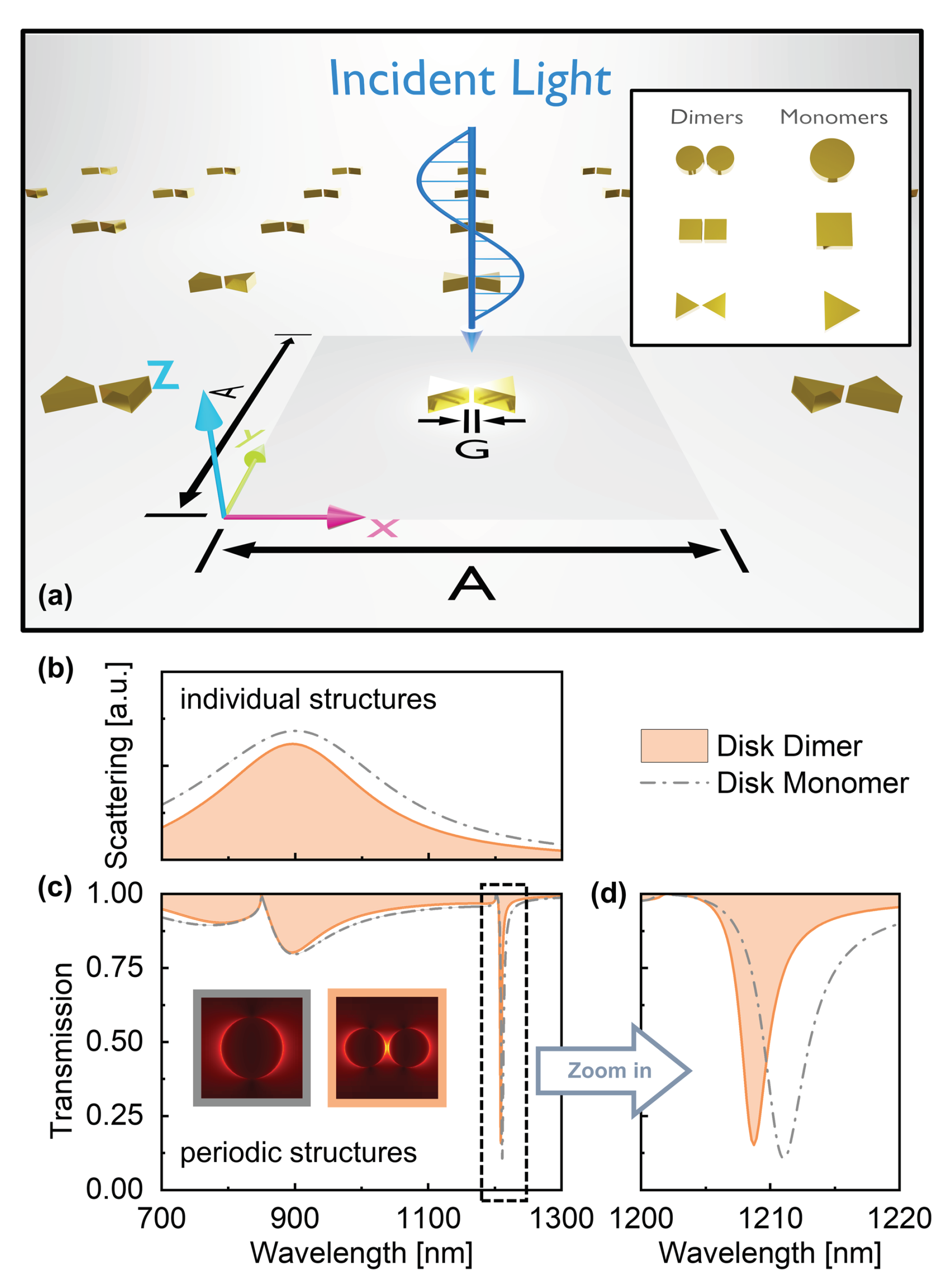
2. Result and Discussion

Plasmonic SLRs are generally supported by nanoscale periodic arrays containing metallic particles as unit cells, an example of which is schematically shown in Figure 1a, where, theoretically, the unit particles can be in various kinds of morphological forms (the insert in Figure 1a). Since a plasmonic SLR originates from the far-field diffractive coupling of the light scattered by the LSPRs of the unit cells, it is reasonable to think that the morphologies of the unit particles will result in differences of their scattering properties and thus affect the damping of the formed plasmonic SLR. For instance, Figure 1b–d show the influences, brought about by the difference in the unit cell’s morphologies, on the scattering intensities of the unit particles and the spectral bandwidths of the corresponding plasmonic SLRs. In order to investigate the influences of structure morphologies on plasmonic SLRs, the LSPR wavelengths corresponding to these diverse forms are designed and set to be the same by tuning the geometrical shapes, cross-section areas, and gaps. In this process, a smaller cross-section area causes a blue shift and a narrower gap causes a red shift, both of which can be used to modulate LSPRs to a specified wavelength. In Figure 1c, the LSPRs of the monomer and dimer are controlled and excited at the same wavelength 800 nm, while the SLRs presenting sharp dips occur near 1200 nm due to the coupling between LSPRs and Rayleigh anomalies [13,45,47]. In addition, the morphologies of the unit cells define the spatial modes that can be supported by the structure system, and thus can affect the near-field properties of the plasmonic SLRs in a large degree, as shown in the insets in Figure 1c. Therefore, we believe that morphology engineering will be a promising tool for the tailoring of both the spectral and spatial properties of plasmonic SLRs. To be specific, the spectral properties mainly mean the spectral bandwidths and the resonance wavelengths of plasmonic SLRs, and the spatial properties mainly indicate the field distributions and FEs. Local field enhancement, so called hot spot, where the electromagnetic field enhancement is spatially excited and confined by the plasmonic nanostructure. Based on this, the following will discuss in detail how to utilize morphology engineering to endow plasmonic SLRs with high Q factors and large FEs at the same time. In addition, the Q factor is generally defined as Q = λ r e s Δ λ (where λ r e s is the resonance wavelength, Δ λ is the width of the resonance) [12], and used to measure the energy storage capacity of a plasmonic system.
As the first step of the exploration, we investigated the scattering properties of the unit particles with different morphologies in their separated state. To make better comparisons, all the wavelengths of the LSPRs of the unit particles are designed to be the same, which is 900 nm in the following. The simulation details can be found in Appendix A.
A variety of typical morphologies of particles were considered in the simulations, including disk, cuboid, triangular prism and their dimer forms with different gaps (inserts in Figure 2a), whose detailed geometric parameters are given in Table 1 and Table 2. As shown in Figure 2a, for the excited dipolar LSPRs (see Supplementary Materials, Figures S4 and S5), although the particles with different morphologies exhibit similar spectral line shapes, distinct differences lay on their scattering intensities and damping rates which are expressed by the spectral linewidths. Particularly, we found strong connections between scattering intensities and Q factors of the separated particle cells and their cross-section areas. To be specific, it is illustrated that high Q factors are achieved by adopting small (geometrical) cross-section areas of unit structures in the plasmonic array, which reduces the scattering of the corresponding LSPR. As shown in Figure 2b, despite of the differences in particle shapes, the scattering intensities of the separated particle cells are typically enlarged together when the cross-section areas of the structures increase, while their Q factors exhibit the converse behaviors. Qualitatively, such connections are because larger cross-section areas increase the areas of the structures interacting with light and enlarge the scattering efficiency, which then boosts the damping rate of the LSPRs.
The diversity in properties of particle cells then brings about different behaviors of the plasmonic SLRs when these particles compose of periodic arrays. As a result, the SLRs of plasmonic nanoarray with different morphologies exhibit different spectral linewidths and differed damping rates, as illustrated in Figure 3a,b (and Figures S1–S3 in Supplementary Materials). For the high-Q plasmonic SLRs, an important damping channel is the radiative loss of the LSPRs of the particle cells through mode coupling. Therefore, the plasmonic nanoarray consisting of particle cells with higher scattering efficiencies tends to support SLRs with lower Q factors, which is in accordance with the simulated results shown in Figure 3c. The Q factors of the plasmonic SLRs can also be estimated by semi-analytical lattice sum calculations [9,13,18,46], although we used numerical simulations in order to achieve higher accuracies. It should be noticed that, to control the variables, all the periods of the simulated nanoarrays in this work are set to be 800 nm.
Actually, the determination of the damping rate of a plasmonic SLR is more complicated because of the existence of other damping channels, such as absorptions, apart from the radiative loss. However, interestingly, despite of the complexity of the real physical processes, we found a simple relationship in the studied cases, where the Q factors of the plasmonic SLRs are inversely proportional to the square of the cross-section areas of the cell particles, as shown in Figure 3d. Such a simple relationship will be useful for the design of high-Q plasmonic SLRs.
When it comes to near-FE, the focuses of elements become quite different, where the spatial modes of the cell particles are more important. We began with the simpler cases of separated cell particles, focusing on the spatial modes and electric FEs of their LSPRs. Since the morphologies of nanoparticles restrict the collective motions of electrons that can be supported, different spatial modes of LSPRs will form when the particle shapes change. As shown by the simulated electric field distributions in Figure 4a, different morphologies result in differed distributions of the electric field, and those with small gaps or sharp edges tend to have a stronger ability in confining light to smaller spaces.
The spatial modes will then affect the FEs that can be achieved by the LSPRs. By plotting the maximum FEs of the LSPRs together (Figure 4b), it is seen that particles with sharp edges, triangular prism monomer and dimer in the presented cases, have distinct advantages in near-FE (the triangle dots in Figure 4b), which is mainly because electrons in metals are easier to gather at such sharp edges. As for the morphologies regarding square and circle, the cuboid possesses larger FE than the case of circle disk, but the circle disk dimers only obtain advantages against the cuboid dimers when the gaps are small enough (the square dots and the circle dots in Figure 4b). This is because the perpendicular edges provide the main advantages for cuboid dimers when the gaps are large; but the smaller faced areas of the disk dimers start to earn stronger advantages when the gaps become narrower, while the larger faced areas of the cuboid dimers result in fewer constraints on the motions of electrons and thus lose the advantages in field confinement. Therefore, dimers with small gaps possess higher densities of positive and negative charges coupled across the gaps, which arouses stronger field intensity [34,48].
When the cell particles are organized together to form periodic nanoarrays and support collective resonances, the spatial modes of the plasmonic SLRs are quite in accordance with that of the LSPRs of the separated cell particle, which can be observed by comparing the results in Figure 4a and Figure 5a. In such comparisons, it can also be found that the effects of near-FE are conspicuously enlarged, giving rise to higher enhancements, and the morphologies of the triangle still possess clear advantages. Actually, by plotting all the maximum enhancements of the SLRs together in Figure 5b, we found that the situation is in high accordance with that in the case of separated cell particles shown in Figure 4b. This can be more clearly seen by plotting the FEs of the SLRs against that of the LSPRs in Figure 5c, where the field intensities of the SLRs are nearly monotonically increasing when that of the corresponding LSPRs increase. These results deliver a useful and important instruction, which is that, from the viewpoint of near-FE, plasmonic SLRs with larger enhancements can be achieved by adopting cell structures supporting LSPRs with stronger enhancing effects.
By now, two instructions have been obtained for the realization of a high-Q plasmonic SLR with large FE: one is reducing the cross-section area of the cell particles to achieve a high Q factor, and the other is designing the LSPR with a strong enhancing effect for the cell particles in order to obtain large electric FE in the corresponding plasmonic SLR. A guideline for realizing high-Q plasmonic SLRs with large FE then turns up after combining these two instructions, which is to design particles with small cross-section areas but strong near-FE as the cell particles of the plasmonic lattice.
According to this guideline, the selection of cell particles is a key point. Therefore, we gathered the cross-section areas of separated particles with different morphologies and their FE of LSPRs in Figure 6a, and spotted a morphology, triangular prism dimer with a gap of 10 nm (the triangle dot highlighted by a pink background in Figure 6a), with the smallest cross-section area and largest FE. According to the guideline, this morphology will possess a plasmonic SLR with the highest Q factor and the strongest field enhancing effect. To verify this prediction, we plotted the Q factors of the corresponding SLRs together with their electric FEs in Figure 6b. The results clearly show that the spotted morphology contributes to the highest Q (up to 2100) and largest FE (up to 592 times), which strongly supports the validity of the presented guideline. More practices of the presented guideline can be found in Figures S6–S9.
Interestingly, as shown in Figure 6b, it seems that the plasmonic SLRs with higher Q factors tend to generate larger near-FEs in some cases. This approximate tendency appears probably because higher Q factors, representing a longer lifetime of photons in cavities, keep more photons in the plasmonic lattice cavities at the same time and result in higher field intensities in the near field. However, due to the diversity in spatial near-field modes and absorption properties, the relationship between the near-FEs and the Q factors is not monotonically increasing. For instance, in Figure 6b, the blue rectangle dot represents a plasmonic SLR with a near-FE much larger than that corresponding to the white circular dot, while the relative magnitudes of their Q factors are the distinct opposite. The relationships between near-field properties, Q factors and absorptions may be worth further theoretical investigations in the future.

3. Conclusions

In summary, we investigated the influences of the particle morphologies on the damping rate and near-field property of a plasmonic SLR, and presented a guideline for achieving SLRs with both high Q factors and strong near-FEs. To be specific, high Q factors were obtained by adopting particles with small cross-section areas as the cell structures of the plasmonic lattice. This stems from our analysis showing that the Q factor of a plasmonic SLR is inversely proportional to the square of the cross-section area of the cell particles. On the other hand, larger near-FEs of plasmonic SLRs were achieved by designing cell particles supporting LSPRs with stronger field enhancing effects. These effects support a simple guideline for achieving a plasmonic SLR with strong FE as well as a high Q factor, which is designing particles with small cross-section areas and large FEs as the unit cell of the periodic array. By following this guideline, we realized a plasmonic SLR with Q factor and FE up to 2100 and 592 times, respectively. It should be noticed that this guideline is valid with a prerequisite where the LSPRs of the cell particles are fixed at the same wavelength, and a more general guideline is worthwhile for future investigations. Our work provides a facile way to design high-performance plasmonic resonances, and may benefit a variety of fields such as biophotonics, nonlinear optics and quantum information processing.

Supplementary Materials

The following supporting information can be downloaded at: https://www.mdpi.com/article/10.3390/photonics10050570/s1.

Author Contributions

H.P. was responsible for simulations and data processing; J.X. provided theoretical guidance and paper writing; Z.P. and C.O. helped edit the paper; H.D., Z.M. and J.Z. helped check the paper. All authors have read and agreed to the published version of the manuscript.

Funding

This research was funded by National Natural Science Foundation of China (62131018, 12104100); Natural Science Foundation of Guangdong Province (2022A1515010027); Guangzhou Municipal Science and Technology Project (202002030210, SL2022A04J01205).

Institutional Review Board Statement

Not applicable.

Informed Consent Statement

Not applicable.

Data Availability Statement

All data are available from the authors upon reasonable request.

Acknowledgments

We sincerely acknowledge Limin Lin for her valuable discussion about this work.

Conflicts of Interest

The authors declare no conflict of interest.

Appendix A. Numerical Method

In this article, electromagnetic simulations have been carried out, based on Finite-Difference Time-Domain (FDTD) method for Lumerical FDTD Solutions. The optical properties of gold were obtained from the job by Johnson and Christy. Structures are surrounded by the background medium with the refractive index n = 1.5 .
Scattered-wave simulations were conducted in a commercial three-dimensional FDTD solver for the individual nanostructures, with perfectly matched layers (PML) in each dimension. The simulation span x, y, and z directions are set to be the same 1800 nm. In addition, scattering, absorption and extinction spectra were derived with the help of a total-field scattered-field source. While under the implementation of full-wave simulations, a single unit cell in a periodic array was simulated using periodic boundary conditions in the x- and y-dimensions and PML in the z-dimension. The simulation span x, y, and z directions are set to be 800, 800, and 1300 nm, respectively. A uniform mesh size of 1 nm, covering the metal region, and a simulation shut-off condition of 10 6 were used to ensure the accuracy of calculations.

References

  1. Beeram, R.; Vepa, K.R.; Soma, V.R. Recent trends in SERS-based plasmonic sensors for disease diagnostics, biomolecules detection, and machine learning techniques. Biosensors 2023, 13, 328. [Google Scholar] [CrossRef]
  2. Danilov, A.; Tselikov, G.; Wu, F.; Kravets, V.G.; Ozerov, I.; Bedu, F.; Grigorenko, A.N.; Kabashin, A.V. Ultra-narrow surface lattice resonances in plasmonic metamaterial arrays for biosensing applications. Biosens. Bioelectron. 2018, 104, 102–112. [Google Scholar] [CrossRef] [PubMed]
  3. Song, M.; Feng, L.; Huo, P.; Liu, M.; Huang, C.; Yan, F.; Lu, Y.Q.; Xu, T. Versatile full-colour nanopainting enabled by a pixelated plasmonic metasurface. Nat. Nanotechnol. 2023, 18, 71–78. [Google Scholar] [CrossRef] [PubMed]
  4. Beiranvand, B.; Khabibullin, R.A.; Sobolev, A.S. Local field enhancement due to the edge states of nanoplasmonic crystal. Photonics 2023, 10, 263. [Google Scholar] [CrossRef]
  5. Zhao, T.; Meng, D.; Hu, Z.; Sun, W.; Ji, Y.; Han, J.; Jin, X.; Wu, X.; Duan, P. Enhanced chiroptic properties of nanocomposites of achiral plasmonic nanoparticles decorated with chiral dye-loaded micelles. Nat. Commun. 2023, 14, 81. [Google Scholar] [CrossRef]
  6. Rong, K.; Gan, F.; Shi, K.; Chu, S.; Chen, J. Configurable integration of on-chip quantum dot lasers and subwavelength plasmonic waveguides. Adv. Mater. 2018, 30, 1706546. [Google Scholar] [CrossRef] [PubMed]
  7. Liang, Y.; Li, C.; Huang, Y.Z.; Zhang, Q. Plasmonic nanolasers in on-chip light sources: Prospects and challenges. ACS Nano 2020, 14, 14375–14390. [Google Scholar] [CrossRef] [PubMed]
  8. Wang, B.; Yu, P.; Wang, W.; Zhang, X.; Kuo, H.C.; Xu, H.; Wang, Z.M. High-Q Plasmonic Resonances: Fundamentals and Applications. Adv. Opt. Mater. 2021, 9, 2001520. [Google Scholar] [CrossRef]
  9. Bin-Alam, M.S.; Reshef, O.; Mamchur, Y.; Alam, M.Z.; Carlow, G.; Upham, J.; Sullivan, B.T.; Ménard, J.M.; Huttunen, M.J.; Boyd, R.W.; et al. Ultra-high-Q resonances in plasmonic metasurfaces. Nat. Commun. 2021, 12, 974. [Google Scholar] [CrossRef] [PubMed]
  10. Taskinen, J.M.; Moilanen, A.J.; Rekola, H.; Kuntze, K.; Priimagi, A.; Torma, P.; Hakala, T.K. All-optical emission control and lasing in plasmonic lattices. ACS Photonics 2020, 7, 2850–2858. [Google Scholar] [CrossRef]
  11. Fang, X.; Xiong, L.; Shi, J.; Li, G. High-Q quadrupolar plasmonic lattice resonances in horizontal metal–insulator–metal gratings. Opt. Lett. 2021, 46, 1546–1549. [Google Scholar] [CrossRef] [PubMed]
  12. Kravets, V.G.; Kabashin, A.V.; Barnes, W.L.; Grigorenko, A.N. Plasmonic surface lattice resonances: A review of properties and applications. Chem. Rev. 2018, 118, 5912–5951. [Google Scholar] [CrossRef]
  13. Cuartero-González, A.; Sanders, S.; Zundel, L.; Fernández-Domínguez, A.I.; Manjavacas, A. Super-and subradiant lattice resonances in bipartite nanoparticle arrays. ACS Nano 2020, 14, 11876–11887. [Google Scholar] [CrossRef] [PubMed]
  14. Zhou, Y.; Guo, Z.; Zhao, X.; Wang, F.; Yu, Z.; Chen, Y.; Liu, Z.; Zhang, S.; Sun, S.; Wu, X. Dual-Quasi Bound States in the Continuum Enabled Plasmonic Metasurfaces. Adv. Opt. Mater. 2022, 10, 2200965. [Google Scholar] [CrossRef]
  15. Zhu, X.; Imran Hossain, G.M.; George, M.; Farhang, A.; Cicek, A.; Yanik, A.A. Beyond noble metals: High Q-factor aluminum nanoplasmonics. ACS Photonics 2020, 7, 416–424. [Google Scholar] [CrossRef]
  16. Le-Van, Q.; Zoethout, E.; Geluk, E.J.; Ramezani, M.; Berghuis, M.; Gómez Rivas, J. Enhanced quality factors of surface lattice resonances in plasmonic arrays of nanoparticles. Adv. Opt. Mater. 2019, 7, 1801451. [Google Scholar] [CrossRef]
  17. Wang, D.; Guan, J.; Hu, J.; Bourgeois, M.R.; Odom, T.W. Manipulating light–matter interactions in plasmonic nanoparticle lattices. Acc. Chem. Res. 2019, 52, 2997–3007. [Google Scholar] [CrossRef]
  18. Reshef, O.; Saad-Bin-Alam, M.; Huttunen, M.J.; Carlow, G.; Sullivan, B.T.; Ménard, J.M.; Dolgaleva, K.; Boyd, R.W. Multiresonant high-Q plasmonic metasurfaces. Nano Lett. 2019, 19, 6429–6434. [Google Scholar] [CrossRef]
  19. Guan, J.; Sagar, L.K.; Li, R.; Wang, D.; Bappi, G.; Wang, W.; Watkins, N.; Bourgeois, M.R.; Levina, L.; Fan, F.; et al. Quantum dot-plasmon lasing with controlled polarization patterns. ACS Nano 2020, 14, 3426–3433. [Google Scholar] [CrossRef]
  20. Yu, H.; Peng, Y.; Yang, Y.; Li, Z.Y. Plasmon-enhanced light–matter interactions and applications. npj Comput. Mater. 2019, 5, 45. [Google Scholar] [CrossRef]
  21. Stolt, T.; Vesala, A.; Rekola, H.; Karvinen, P.; Hakala, T.K.; Huttunen, M.J. Multiply-resonant second-harmonic generation using surface lattice resonances in aluminum metasurfaces. Opt. Express 2022, 30, 3620–3631. [Google Scholar] [CrossRef] [PubMed]
  22. Winkler, J.M.; Ruckriegel, M.J.; Rojo, H.; Keitel, R.C.; De Leo, E.; Rabouw, F.T.; Norris, D.J. Dual-wavelength lasing in quantum-dot plasmonic lattice lasers. ACS Nano 2020, 14, 5223–5232. [Google Scholar] [CrossRef] [PubMed]
  23. Wang, D.; Bourgeois, M.R.; Guan, J.; Fumani, A.K.; Schatz, G.C.; Odom, T.W. Lasing from finite plasmonic nanoparticle lattices. ACS Photonics 2020, 7, 630–636. [Google Scholar] [CrossRef]
  24. Movsesyan, A.; Besteiro, L.V.; Kong, X.T.; Wang, Z.; Govorov, A.O. Engineering strongly chiral plasmonic lattices with achiral unit cells for sensing and photodetection. Adv. Opt. Mater. 2022, 10, 2101943. [Google Scholar] [CrossRef]
  25. Wang, L.; Wang, Q.; Wang, T.Q.; Zhao, W.M.; Yin, X.Y.; Jiang, J.X.; Zhang, S.S. Plasmonic crescent nanoarray-based surface lattice resonance sensor with a high figure of merit. Nanoscale 2022, 14, 6144–6151. [Google Scholar] [CrossRef]
  26. Chang, K.H.; Cheng, J.S.; Lu, T.W.; Lee, P.T. Engineering surface lattice resonance of elliptical gold nanodisk array for enhanced strain sensing. Opt. Express 2018, 26, 33215–33225. [Google Scholar] [CrossRef]
  27. Hooper, D.C.; Kuppe, C.; Wang, D.; Wang, W.; Guan, J.; Odom, T.W.; Valev, V.K. Second harmonic spectroscopy of surface lattice resonances. Nano Lett. 2018, 19, 165–172. [Google Scholar] [CrossRef]
  28. Chen, S.; Reineke, B.; Li, G.; Zentgraf, T.; Zhang, S. Strong nonlinear optical activity induced by lattice surface modes on plasmonic metasurface. Nano Lett. 2019, 19, 6278–6283. [Google Scholar] [CrossRef]
  29. Beer, S.; Gour, J.; Alberucci, A.; David, C.; Nolte, S.; Zeitner, U.D. Second harmonic generation under doubly resonant lattice plasmon excitation. Opt. Express 2022, 30, 40884–40896. [Google Scholar] [CrossRef]
  30. Michaeli, L.; Keren-Zur, S.; Avayu, O.; Suchowski, H.; Ellenbogen, T. Nonlinear surface lattice resonance in plasmonic nanoparticle arrays. Phys. Rev. Lett. 2017, 118, 243904. [Google Scholar] [CrossRef]
  31. Liu, W.; Lee, B.; Naylor, C.H.; Ee, H.S.; Park, J.; Johnson, A.C.; Agarwal, R. Strong exciton–plasmon coupling in MoS2 coupled with plasmonic lattice. Nano Lett. 2016, 16, 1262–1269. [Google Scholar] [CrossRef] [PubMed]
  32. Luo, Y.; Shepard, G.D.; Ardelean, J.V.; Rhodes, D.A.; Kim, B.; Barmak, K.; Hone, J.C.; Strauf, S. Deterministic coupling of site-controlled quantum emitters in monolayer WSe2 to plasmonic nanocavities. Nat. Nanotechnol. 2018, 13, 1137–1142. [Google Scholar] [CrossRef] [PubMed]
  33. Liu, W.; Wang, Y.; Zheng, B.; Hwang, M.; Ji, Z.; Liu, G.; Li, Z.; Sorger, V.J.; Pan, A.; Agarwal, R. Observation and active control of a collective polariton mode and polaritonic band gap in few-layer WS2 strongly coupled with plasmonic lattices. Nano Lett. 2019, 20, 790–798. [Google Scholar] [CrossRef]
  34. Dombi, P.; Pápa, Z.; Vogelsang, J.; Yalunin, S.V.; Sivis, M.; Herink, G.; Schäfer, S.; Groß, P.; Ropers, C.; Lienau, C. Strong-field nano-optics. Rev. Mod. Phys. 2020, 92, 025003. [Google Scholar] [CrossRef]
  35. Forn-Díaz, P.; Lamata, L.; Rico, E.; Kono, J.; Solano, E. Ultrastrong coupling regimes of light–matter interaction. Rev. Mod. Phys. 2019, 91, 025005. [Google Scholar] [CrossRef]
  36. Lin, Q.Y.; Li, Z.; Brown, K.A.; O’Brien, M.N.; Ross, M.B.; Zhou, Y.; Butun, S.; Chen, P.C.; Schatz, G.C.; Dravid, V.P.; et al. Strong coupling between plasmonic gap modes and photonic lattice modes in DNA-assembled gold nanocube arrays. Nano Lett. 2015, 15, 4699–4703. [Google Scholar] [CrossRef]
  37. Suh, J.Y.; Kim, C.H.; Zhou, W.; Huntington, M.D.; Co, D.T.; Wasielewski, M.R.; Odom, T.W. Plasmonic bowtie nanolaser arrays. Nano Lett. 2012, 12, 5769–5774. [Google Scholar] [CrossRef]
  38. Kauranen, M.; Zayats, A.V. Nonlinear plasmonics. Nat. Photonics 2012, 6, 737–748. [Google Scholar] [CrossRef]
  39. Noordam, M.; Hernandez-Rueda, J.; Talsma, L.; Kuipers, L. Plasmon-induced enhancement of nonlinear optical processes in a double-resonant metallic nanostructure grating. Appl. Phys. Lett. 2020, 116, 101101. [Google Scholar] [CrossRef]
  40. Lin, L.; Xue, J.; Xu, H.; Zhao, Q.; Zhang, W.; Zheng, Y.; Wu, L.; Zhou, Z.K. Integrating lattice and gap plasmonic modes to construct dual-mode metasurfaces for enhancing light–matter interaction. Sci. China Mater. 2021, 64, 3007–3016. [Google Scholar] [CrossRef]
  41. Shen, Q.; Jin, W.; Yang, G.; Rodriguez, A.W.; Mikkelsen, M.H. Active control of multiple, simultaneous nonlinear optical processes in plasmonic nanogap cavities. ACS Photonics 2020, 7, 901–907. [Google Scholar] [CrossRef]
  42. Chen, J.; Gan, F.; Wang, Y.; Li, G. Plasmonic Sensing and Modulation Based on Fano Resonances. Adv. Opt. Mater. 2018, 6, 1701152. [Google Scholar] [CrossRef]
  43. Elshorbagy, M.H.; Cuadrado, A.; González, G.; González, F.J.; Alda, J. Performance improvement of refractometric sensors through hybrid plasmonic–fano resonances. J. Light. Technol. 2019, 37, 2905–2913. [Google Scholar] [CrossRef]
  44. Chen, Z.; Zhang, S.; Chen, Y.; Liu, Y.; Li, P.; Wang, Z.; Zhu, X.; Bi, K.; Duan, H. Double Fano resonances in hybrid disk/rod artificial plasmonic molecules based on dipole-quadrupole coupling. Nanoscale 2020, 12, 9776–9785. [Google Scholar] [CrossRef] [PubMed]
  45. Cherqui, C.; Bourgeois, M.R.; Wang, D.; Schatz, G.C. Plasmonic surface lattice resonances: Theory and computation. Acc. Chem. Res. 2019, 52, 2548–2558. [Google Scholar] [CrossRef]
  46. Manjavacas, A.; Zundel, L.; Sanders, S. Analysis of the limits of the near-field produced by nanoparticle arrays. ACS Nano 2019, 13, 10682–10693. [Google Scholar] [CrossRef]
  47. Baur, S.; Sanders, S.; Manjavacas, A. Hybridization of lattice resonances. ACS Nano 2018, 12, 1618–1629. [Google Scholar] [CrossRef]
  48. Yao, X.; Jiang, S.; Luo, S.; Liu, B.W.; Huang, T.X.; Hu, S.; Zhu, J.; Wang, X.; Ren, B. Uniform periodic bowtie SERS substrate with narrow nanogaps obtained by monitored pulsed electrodeposition. ACS Appl. Mater. Interfaces 2020, 12, 36505–36512. [Google Scholar] [CrossRef]
Figure 1. (a) Schematic illustration of a gold triangular prism dimer array with same lattice constant A = 800 nm. Insert: 6 typical kinds of Au dimers or monomers to be taken into account, including the morphologies of circle, square and triangle with varied sizes but the same thickness, T = 40 nm. Incident light propagates along the -z direction with polarization parallel to the x-axis. The spatial refractive index of the environment n = 1.5 . (bd) Simulated results of (b) the scattering spectra of individual disk dimer and monomer, (c) the transmission spectra of periodic disk dimer and monomer arrays, with the field distributions of the surface lattice resonance (SLR) in the inserts, and (d) the zoom-in spectra of (c) with the wavelengths ranging from 1200 to 1220 nm.
Photonics 10 00570 g001
Figure 2. Optical response and quality (Q) factor of separated unit-cell nanoparticles. (a) The scattering spectra of disk, cuboid and triangular prism particles, including monomers (dotted lines) and dimers (solid lines) with different gaps. Peak wavelengths of the particles are all tuned to be λ = 900 nm. (b) The scattering intensities and Q factors as functions of the cross-section areas of the particles, including the monomers and the dimers. As the legend shows, the markers of the circle, square and triangle represent the corresponding shapes of the individual particles. The markers filled into white, grey, orange and blue represent monomer, and dimer with G = 10 nm, 30 nm and 50 nm, respectively. The geometric details of the simulated structures are provided in Table 1 and Table 2.
Photonics 10 00570 g002
Figure 3. Optical response and Q factor of periodic nanoparticles. (a,b) Typical transmission spectra of periodic dimer and monomer arrays, including the shapes of circle, square and triangle. More transmission spectra can be found in Figures S1–S3. (b) The zoom-in spectra of (a). (c) The relationship between Q factor and scattering intensity. (d) The Q factors of plasmonic lattices’ SLRs with varied cross-section areas of their unit particles. The light red line is a fitting curve for y = A x 2 (where A = 1.67 . y and x represent Q factor and cross-section area, respectively). The representations of marker shapes and colors are shown in the legend.
Photonics 10 00570 g003
Figure 4. Localized electric field profiles and enhancements of separated cell nanoparticles ( E LSPR ). (a) electric field profiles of monomers and their corresponding dimers with G = 10 nm. The hot spot can be directly found and the scale bar is placed on the right side for each profile. (b) E LSPR of dimers with gap size G, as well as that of monomers.
Photonics 10 00570 g004
Figure 5. (a,b) Localized electric field profiles (a) and electric field enhancements (b) of periodic nanoparticles ( E SLR ), with cell particles the same as Figure 4. (c) E SLR with different electric field enhancements of separated cell particles ( E LSPR ).
Photonics 10 00570 g005
Figure 6. (a) Electric field enhancements of separated particles ( E LSPR ) as a function of their cross-section areas. (b) The electric field enhancements of the plasmonic SLRs of periodic particles ( E SLR ) corresponding to their Q factors. Notably, the dot marked by the pink circle shadow presents the best performance, with E SLR up to 592 times and Q factor up to 2100.
Photonics 10 00570 g006
Table 1. The particle diameters or lengths are included and shown here. The sizes of all nanostructures, whose LSPRs are excited at λ r e s = 900 nm in this article. In addition, the thicknesses of them are 40 nm. D is the diameter of the circle (disk) or circumdiameter of the triangle (triangular prism). L is side length of a square (cuboid).
Size [nm]MonomerDimer
No Gap10 nm30 nm50 nm
Disk D = 176 D = 110 D = 134 D = 147
Cuboid L = 136.5 L = 85 L = 103 L = 113
Triangular Prism D = 174 D = 116 D = 140 D = 151
Table 2. The particle cross-section areas corresponding to Table 1 are included and shown here.
Cross-Section Area [ nm 2 ]MonomerDimer
No Gap10 nm30 nm50 nm
Disk24,328.4919,006.6428,205.2133,943.34
Cuboid18,632.0014,450.0021,218.0025,538.00
Triangular Prism9832.408739.9312,730.5714,809.68
Disclaimer/Publisher’s Note: The statements, opinions and data contained in all publications are solely those of the individual author(s) and contributor(s) and not of MDPI and/or the editor(s). MDPI and/or the editor(s) disclaim responsibility for any injury to people or property resulting from any ideas, methods, instructions or products referred to in the content.

