Abstract
In this paper, a microwave phase compensation scheme is adopted. It utilizes microwave signals of different frequencies for round-trip signal transmission over a 250 km fiber optic link to mitigate the impact of parasitic reflections. Additionally, dispersion compensation fibers are employed to compensate for the dispersion in the fiber optic link. Bidirectional optical amplifiers are utilized to compensate for the losses in long-distance fiber optic links and reduce optical path asymmetry. By implementing these methods, the transmission stability of the fiber optic microwave frequency transmission system achieves 5.6 × 10⁻¹⁵ at 1 s and 2.8 × 10⁻¹⁸ at 100,000 s.
1. Introduction
With the advancements in atomic clock technology, traditional satellite-based frequency transmission methods no longer meet the requirements for long-distance transmission and comparison of modern atomic frequency standards. Long-distance and high-precision frequency transmission technology plays a crucial role in various fields, including radio telescope arrays [1,2,3,4], time and frequency synchronization networks [5,6], real-time comparison and coordination of remote atomic clocks [7,8,9], geodesy, and basic science [10,11]. With the continuous development of optical fiber link infrastructure, the use of optical fiber links for microwave frequency transmission has gained popularity due to their low loss, strong anti-interference capabilities, and electromagnetic silence, providing excellent transmission performance. Optical fiber microwave frequency transmission technology has emerged as an effective method to achieve long-distance and high-precision frequency transmission.
Currently, there are two main categories of implementation schemes for long-distance and high-precision fiber optic microwave frequency transmission: optical phase compensation [12] and microwave phase compensation [13,14]. The optical phase compensation scheme compensates for additional disturbances in the fiber optic link by controlling the transmission delay of the signal light. For instance, in 2010, the Paris Observatory achieved 9.15 GHz signal transmission over an 86 km fiber using the optical phase compensation scheme, with transmission stabilities of 1 × 10⁻¹⁵ at 1 s and 2 × 10⁻¹⁹ at one day [15]. In contrast, the microwave phase compensation scheme directly controls the phase of the microwave signal transmitted through the electrical part, compensating for disturbances in the fiber optic link. The compensation actuator typically used is a voltage-controlled crystal oscillator. In 2012, Tsinghua University realized 9.1 GHz microwave phase compensation transmission over an 80 km field fiber, achieving transmission stabilities of 7 × 10⁻¹⁵ at 1 s and 5 × 10⁻¹⁹ at one day [13]. The optical phase compensation scheme generally consists of two parts. The first part uses a piezoelectric transducer (PZT) to compensate for fast and relatively small phase disturbances in fiber optic links; the second part is to use temperature-controlled compensating optical fibers to compensate for phase disturbances that slowly change and fluctuate significantly in the fiber optic link. The structure of this scheme is relatively complex, with a large volume, and due to the introduction of temperature-controlled compensating optical fibers, the loss of the entire optical fiber link increases, making single-stage propagation unsuitable for long-distance transmission; However, the fiber link symmetry of optical phase compensation is better than that of microwave phase compensation; The microwave phase compensation adopts a phase-locked loop to control the voltage controlled oscillator to adjust the signal phase, with a simple structure and convenient engineering implementation. It is suitable for long-distance fiber optic microwave frequency transmission.
The aforementioned studies focused on microwave frequency signal transmission over fiber optic links of approximately 100 km. However, research institutions are also conducting experiments for longer-distance fiber optic microwave frequency transmission methods. In 2013, the AGH University of Science and Technology in Poland carried out the time and frequency transmission experiment of a 420 km fiber link, with a signal transmission stability of 10 MHz Allan deviation of the order of 4 × 10⁻¹⁷ at one day. In 2021, the Beijing University of Posts and Telecommunications conducted a 1007 km microwave phase compensation experiment, achieving transmission stability of 8.2 × 10⁻¹⁴ at 1 s and 7.78 × 10⁻¹⁷ at 10,000 s [16]. In 2022, Tsinghua University performed on-site fiber optic link experiments over a distance of 300 km, with transmission stabilities of 2.2 × 10⁻¹⁴ at 1 s and 2.6 × 10⁻¹⁷ at one day, and laboratory fiber optic reel experiments over a distance of 500 km, with transfer stabilities of 1.7 × 10⁻¹⁴ at 1 s and 6.7 × 10⁻¹⁸ at 100,000 s [17]. In 2022, the National Time Service Center (NTSC) achieved 212 km optical fiber microwave frequency transmission by cascading method and achieved a microwave frequency transmission stability of 6.2 × 10⁻¹⁵ at 1 s and 6.4 × 10⁻¹⁸ at 40,000 s through the on-site link from Lintong site and Chang’an site (both in Xi’an) [18].
There are three main methods to study the scheme of long-distance optical fiber microwave frequency transmission: first, multiple optical amplifiers are used to amplify the optical signal to increase the transmission distance, such as Beijing University of Posts and Telecommunications [16] and Tsinghua University [17]. In order to further reduce the loss of optical power, Tsinghua University uses Bragg grating instead of negative dispersion compensation fiber to reduce the power loss caused by dispersion compensation fiber. However, it increases the asymmetry of fiber optic links. The second method is to achieve long-distance transmission of fiber optic microwave frequency using cascading single-stage devices, such as the cascading transmission of the national time service center on a 212 km fiber optic link [18]. The third method is to increase the distance of fiber optic microwave transmissions via optical–electrical–optical conversion. Currently, it is mainly applied in the field of fiber optic communication, mainly by demodulating and amplifying the microwave signal on the fiber optic link using PD after the optical signal is transmitted for a certain distance and then directly modulating it to the fiber optic link for further transmission. Through the conversion of optical–electrical–optical, the signal-to-noise (SNR) ratio of the microwave signal is improved, enabling them to transmit over longer distances. Among these three methods, the cascading transfer method has a wider phase-locked bandwidth compared to the other two methods, which does not change the existing equipment. The disadvantage is that a single set of equipment is expensive, and the transmission stability decays as the number of cascading equipment sets increases in a square root relationship. The expression is as follows: , where is the stability of the nth set of equipment. The use of multiple bidirectional optical amplifiers for long-distance fiber microwave frequency transmission is simpler in structure, lower in cost, and more conducive to long-distance transmission compared to optical–electrical–optical conversion.
In this study, a microwave phase compensation scheme is adopted. It utilizes microwave signals of different frequencies for round-trip signal transmission over a 250 km fiber optic link to mitigate the impact of parasitic reflections. Additionally, dispersion compensation fibers are employed to compensate for the dispersion in the fiber optic link. Bidirectional optical amplifiers are utilized to compensate for the losses in long-distance fiber optic links and reduce optical path asymmetry. By implementing these methods, the transmission stability of the fiber optic microwave frequency transmission system achieves 5.6 × 10⁻¹⁵ at 1 s and 2.8 × 10⁻¹⁸ at 100,000 s. This article is mainly divided into the following parts. In Section 2, we describe the principle of the microwave frequency dissemination system. In Section 3, the two main factors affecting the distance of fiber optic microwave frequency transmission links were analyzed: attenuation of optical power and fiber dispersion; compensation made using bidirectional optical amplifiers and negative dispersion optical fibers. Based on this, 100 km and 250 km fiber optic microwave transmission links were designed, respectively. In Section 4, we tested the transmission results of microwave frequency signals on a 250 km fiber optic link and conducted a simple analysis. Finally, a summary of the entire article was provided.
2. Theoretical and Experimental Systems
When the frequency signal is transmitted along the optical fiber link, due to the influence of the external environment (temperature change and mechanical vibration, etc.), the transmission delay of the signal light is affected, and the phase of the microwave signal is changed, resulting in the deterioration of the transmission stability of the transmitted signal. To achieve long-distance and high-precision frequency signal transmission, the signal light is typically sent back and forth along the fiber optic link, assuming that the round-trip time delay is consistent. By comparing the phase changes of the round-trip signal frequency, it is possible to determine the amount of phase disturbance introduced by the fiber optic link. Phase-locked technology is then applied to real-time compensation for the phase disturbance, thereby improving the transmission stability of the microwave signals.
Figure 1 illustrates the structure of the optical fiber microwave frequency transmission system, which is divided into two parts: the local end and the remote end. After modulating the microwave signal to the optical carrier, it is transmitted from the local end to the remote end through a fiber optic link, demodulated to obtain the received microwave signal at the remote end, filtered, and amplified. Then, the signal is quartered, modulated to the fiber optic link, and transmitted back to the local end for PD detection. The demodulated microwave signal will carry the phase delay introduced by the fiber optic link’s round-trip propagation. Finally, on the local end, the detection and compensation of fiber optic link noise is achieved by detecting the phase difference between the transmitted signal and the returned microwave signal. Due to the fact that the amplitude of the microwave signal does not affect the stability of the transmitted signal during fiber optic microwave frequency transmission, the amplitude factor of the microwave signal is ignored in the following analysis process. The reference signal at the local end is 4 GHz, generated by a commercial signal source (Keysight E8257D).
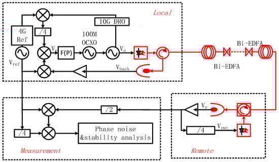
Figure 1.
Scheme of the microwave frequency dissemination system.
is the frequency of the local reference signal, and is the phase of the reference signal. The transmission signal frequency at the local end is 10 GHz, generated by a voltage-controlled oscillator (DRO) locked in a 100 MHz Oven Controlled Crystal Oscillator (OCXO), denoted as follows:
where is phase disturbance introduced by optical fiber link. The 10G signal demodulated from the remote application PD signal is expressed as follows:
After dividing by four frequencies, the signal is obtained as follows:
Similarly, it is transmitted back to the local end through intensity external modulation, and is demodulated using a high-speed photodetector at the local end. Due to the phase fluctuation introduced by the fiber optic link being proportional to the transmission frequency, can be expressed as follows:
The phase of contains the phase fluctuations caused by the round-trip link. The specific scheme of link phase noise detection and compensation is as follows: is obtained by quartering the signal after mixing the reference signal with the transmission signal .
The receiving signal at the local end mixes with the reference signal to obtain as follows:
After mixing and , the error signal is obtained. not only contains the phase difference introduced by the link but also contains the phase difference between and , which is expressed as follows:
When the phase-locked loop is closed, the loop filter controls the phase of the transmitted signal so that , then there is the following equation:
Therefore, the received signal at the remote end can be expressed as follows:
It is locked in phase to the reference signal , the compensation of fiber optic link noise is completed, achieving long-distance transmission of microwave signals.
In addition, the transfer stability can be computed directly from the phase noise as follows [19]:
where is the phase noise of the receive signal referred to as the reference signal of the local site, which is determined by the system noise floor of the dissemination system and residual phase noise introduced by the fiber link . is the frequency of the measured signal.
To evaluate the performance of frequency transfer, a heterodyne system (shown in Figure 1) is designed to measure the phase difference between the reference signal and the received signal in a closed loop. In the measurement system, the 4 GHz reference signal is split into two arms. In the first arm, is directly mixed with the 5 GHz signal generated from using a low-noise frequency divider (Analog Devices, HMC364) to generate a 1 GHz signal. In the second arm, is also frequency-divided to another 1 GHz signal using another low-noise frequency divider (Analog Devices, HMC365). The phase difference between and is down-converted to a direct current (DC) voltage V(t) by mixing the two 1 GHz signals, which is then measured using a multimeter (Keysight, 3458A) with an effective measurement bandwidth of about 3 Hz. V(t) represents the phase difference between the measured signal and the reference signal. From the change in the phase difference, the delay jitter of the optical fiber transmission link can be solved, and then the stability of the optical fiber microwave transmission can be calculated. The specific process is as follows: A multimeter (3458A Keysight) is used to measure the voltage signal V(t), and the voltage data are recorded at a 1 s sampling interval. The voltage signal V(t) data are converted into transmission delay difference data , through the following formula conversion, where A is the peak–peak value of V(t) when the phase of the measured signal V(t) changes in the range of 2π, and is the angular frequency of the transmitted signal at 10 GHz. The Allan variance of can be calculated to characterize the stability of the fiber transmission link.
3. Experimental Setup
When using fiber optic links for fiber optic microwave frequency transmission, attenuation is one of the most important characteristics of fiber optic links. Fiber attenuation determines the maximum direct connection distance of the fiber optic link without the use of an optical amplifier. In order to increase the distance of optical fiber microwave frequency transmission, after the signal light transmission has a certain distance decay, the bidirectional optical amplifier of Bigger Company is used to amplify the signal light to make its transmission distance longer. The structure of bidirectional EDFA is shown in Figure 2. The 980 nm pump light is divided into two beams with the same power by a 50/50 beam splitter, which is, respectively, injected into the erbium-doped fiber from the wavelength-division multiplexing (WDM) on both sides. In this way, the bidirectional pumped EDFA can be realized. Compared with the bidirectional optical amplifier composed of the traditional two unidirectional EDFAs, this pumping mode ensures the symmetry of the transmission link, and, at the same time, the utilization rate of erbium particles is also higher.
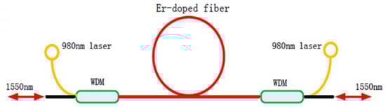
Figure 2.
Structure of bidirectional EDFA.
Meanwhile, in the process of fiber optic microwave frequency transmission, fiber dispersion is one of the main factors affecting the transmission distance of fiber optic links. The RF signal is intensity modulated to an optical carrier, with two sidebands occurring on the optical carrier. During fiber transmission, these two sidebands will experience different amounts of phase accumulation caused by dispersion [20]. When detected using a photodetector (PD), the recovered RF power will change periodically according to the phase difference between the two sidebands. As a result of the dissemination length, dispersion parameter, and frequency of the RF signal, the recovered RF power is formulated as follows:
where is the length of the fiber, is the vacuum light speed, is the frequency of the RF signal, is the optical carrier wavelength, and is the fiber dispersion coefficient. The detected RF power changes periodically with the dissemination length, and the complete extinction occurs at the length of the following:
For the radio frequency signal transmitted via a 1550 nm optical carrier on a single mode fiber link with a dispersion coefficient of 17 ps/nm/km, the extinction period length is 3673 km when the frequency of the radio frequency signal is 1 GHz. But when the frequency of the radio frequency signal increases to 10 GHz, the cycle length will decrease to 36.7 km. This means that for a specific fiber length, a higher radio frequency will result in more power extinction points, which limits its application in actual fiber links.
Therefore, we adopt a dispersion compensating fiber (DCF) with a large negative dispersion coefficient to solve the dispersion problem in fiber optic links. Compared to reference [18], the research team at Tsinghua University used Bragg gratings to compensate for fiber link dispersion and unidirectional EDFA to amplify optical power when conducting long-distance fiber microwave frequency transmission. Although Bragg gratings compensate for dispersion and reduce optical power loss compared to negative dispersion optical fibers, this method can increase the asymmetry of fiber propagation links and affect long-term stability.
In this experiment, we set up a 100 km optical fiber microwave frequency transmission link and a 250 km optical fiber microwave frequency transmission link. The 100 km fiber frequency transmission link consists of two 50 km fiber reels with attenuations of 11 dB and 10 dB, respectively. Between the two reels, a bidirectional EDFA is used to amplify the signal light. At the output end of the signal light, 100 km dispersion compensation fiber is used to compensate for the fiber dispersion in the link, and the loss of the dispersion compensation fiber is 7 dB. The connection diagram of optical fiber links is shown in Figure 3.
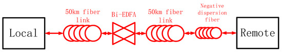
Figure 3.
Scheme of 100 km fiber optic link.
In the process of building a 250 km fiber optic microwave link, four rolls of 50 km fiber are first composed of two pairs of 100 km fiber optic spools. Then, the last roll of 50 km fiber optic spools is added to the link, and the losses of these three fiber optic spools are measured. The corresponding optical power loss values are shown in Table 1. In order to reduce the impact of fiber dispersion on fiber optic transmission links, a negative dispersion compensation fiber that matches 250 km was inserted at an appropriate position in the fiber optic link for fiber optic link dispersion compensation. The loss value of the dispersion compensation fiber was measured, as shown in Table 1. According to Table 1, the total optical power loss of the fiber optic transmission link is 73 dB. In order to ensure that the optical power of the fiber optic transmission link meets the detection range of the photodetector, four pairs of low noise bidirectional optical power amplifiers are used for signal light power amplification, with each amplifier set with a round-trip amplification gain of 15–20 dB. The specific optical path connection diagram is shown in the following Figure 4.

Table 1.
Details of the 250 km fiber link.
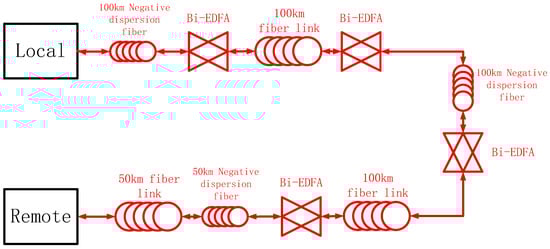
Figure 4.
Scheme of 250 km fiber optic link.
4. Experimental Results and Analysis
Figure 5 displays the transmission delay fluctuations of the microwave signals on the 250 km optical fiber link. The blue curve represents the delay test data of the free-running link, corresponding to the left axis. The red curve represents the delay test results of the compensated link, corresponding to the right axis. For the 250 km free-running link, the test results over three days indicate that the transmission delay fluctuation is approximately 17 ns per day. After closed-loop compensation, the peak-to-peak value of the transmission delay jitter is less than 0.8 ps, and the compensation suppression ratio exceeds 20,000. These results demonstrate that the phase of the remote 10 GHz received signal is well synchronized with the local reference source, and the phase delay disturbance introduced by the optical fiber link is effectively compensated.
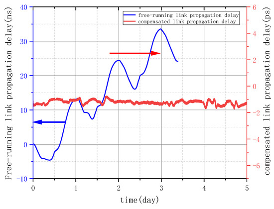
Figure 5.
Delay fluctuation of the 250 km.
Figure 6 depicts the residual phase noise power spectral density (PSD) of the 250 km optical link, both in the free-running state (blue trace) and after compensation (red trace), measured at 10 GHz using Symmetricom 5125A. The residual noise PSD of the free link is obtained by measuring and , while the residual phase noise after locking is obtained by measuring and . The compensation peak value of the 250 km optical fiber link, after the phase-locked loop, is approximately 130 Hz, which is less than 1/4τ [21], consistent with the reference. Additionally, the transmission system effectively compensates for the phase noise introduced by the fiber optic link within the compensation bandwidth range.
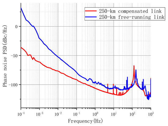
Figure 6.
Residual phase noise PSD of the 250 km.
Figure 7 illustrates the transient stability of the system. The blue curve represents the transient stability of the free-running link, calculated using the delay data from the blue curve in Figure 2. The red curve represents the frequency transmission stability of the compensated link, obtained after a week of continuous operation of the microwave signal transmission system in the closed-loop configuration. By calculating the Allan variance, the results are determined to be 5.6 × 10⁻¹⁵ at 1 s and 2.8 × 10⁻¹⁸ at 100,000 s. The black curve represents the background noise or bottom noise of the system, obtained from the test of a 0 km fiber after closed-loop operation. It can be observed that the transmission stability of the 250 km compensated link is slightly worse than the system’s bottom noise. This can be attributed to two main factors: (1) as the link length increases, the ability to suppress noise decreases, resulting in reduced transmission stability; (2) microwave leakage from the local and remote microwave modules, being placed in the same room during the experiment, can affect signal stability.
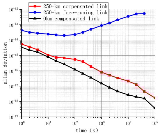
Figure 7.
Frequency transfer instability of each segment.
In Figure 8, the blue curve shows the frequency transfer stability of a 100 km fiber optic link, which was 3.98 × 10⁻¹⁵ at 1 s and 1.4 × 10⁻¹⁸ at 100,000 s. The red line is the result of the 212 km field fiber optic cascade test described in reference [18], which was 6.2 × 10⁻¹⁵ at 1 s and 6.4 × 10⁻¹⁵ at 40,000 s. The black line represents the frequency transmission stability of a 250 km fiber optic link, which was 5.6 × 10⁻¹⁵ at 1 s and 2.8 × 10⁻¹⁸ at 100,000 s. From the figure, it can be seen that the 250 km fiber optic reel link exhibits poor second stability and long stability compared to the 100 km fiber optic reel link. This is mainly due to the introduction of the corresponding noise in fiber dispersion, signal-to-noise ratio, and fiber amplifier as the distance of light increases. At the same time, it can be seen from the figure that the frequency transmission stability of the 250 km fiber optic reel is better than that of the 212 km field fiber optic cascade transmission, mainly due to the following reasons: firstly, the 212 km fiber optic transmission link uses field fiber optic, and its fiber loss is greater than that of the fiber optic reel; secondly, 212 km of on-site optical fibers are more affected by the environment than 250 km of optical fiber reels. At the same time, in this reference, 212 km of field optical fiber was directly amplified using EDFA, and the results of frequency transfer stability were worse than those of two-stage cascades. The main reason is that the parameters of the phase-locked loop have not been adjusted. For longer fiber transmission links, the compensation bandwidth is narrower, so the corresponding parameters of the phase-locked loop need to be optimized.
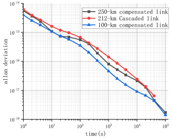
Figure 8.
Transmission stability of fiber optic microwave links using different methods.
5. Conclusions
In conclusion, this article demonstrates the effectiveness of a microwave phase compensation scheme in achieving a 250 km fiber optic link frequency transmission system with transmission stabilities of 5.6 × 10⁻¹⁵ at 1 s and 2.8 × 10⁻¹⁸ at 100,000 s. Further experiments will focus on studying the method of microwave frequency transmission through even longer distances of hundreds or thousands of kilometers of optical fiber. With the continuous improvement of fiber optic links, long-distance and high-precision fiber optic microwave frequency transmission systems will continue to play a crucial role in various applications and scientific research endeavors.
Author Contributions
Conceptualization, S.Y., W.Z. and W.X.; Data curation, S.Y. and W.Z.; Formal analysis, S.Y. and W.Z.; Funding acquisition, W.Z.; Methodology, S.Y., W.Z. and W.X.; Software, S.Y.; Supervision, W.Z., W.X. and S.Z. All authors have read and agreed to the published version of the manuscript.
Funding
This work was supported in part by the National Natural Science Foundation of China (NSFC) (61825505, 91536217) and in part by the West Light Foundation of the Chinese Academy of Sciences (29202082).
Institutional Review Board Statement
Not Applicable.
Informed Consent Statement
Not Applicable.
Data Availability Statement
Not Applicable.
Conflicts of Interest
The authors declare no conflict of interest.
References
- Grainge, K.; Alachkar, B.; Amy, S.; Barbosa, D.; Bommineni, M.; Boven, P.; Braddock, R.; Davis, J.; Diwakar, P.; Francis, V.; et al. Square Kilometre Array: The radio telescope of the XXI century. Astron. Rep. 2017, 61, 288–296. [Google Scholar] [CrossRef]
- Selina, R.J.; McKinnon, M.; Beasley, A.J.; Murphy, E.J.; Carilli, C.; Butler, B.; Clark, B.; Erickson, A.; Grammer, W.; Jackson, J.; et al. The Next-Generation Very Large Array: A technical overview. Proc. SPIE 2018, 10700, 107001O. [Google Scholar] [CrossRef]
- He, Y.; Baldwin, K.; Orr, B.J.; Warrington, R.B.; Wouters, M.; Luiten, A.; Mirtschin, P.; Tzioumis, A.; Phillips, C.; Stevens, J.; et al. Long-distance telecom-fiber transfer of a radio-frequency reference for radio astronomy. Optica 2018, 5, 138–146. [Google Scholar] [CrossRef]
- Clivati, C.; Aiello, R.; Bianco, G.; Bortolotti, C.; De Natale, P.; Di Sarno, V.; Maddaloni, P.; Maccaferri, G.; Mura, A.; Negusini, M.; et al. Common-clock very long baseline interferometry using a coherent optical fiber link. Optica 2020, 7, 1031. [Google Scholar] [CrossRef]
- Gao, C.; Wang, B.; Chen, W.L.; Bai, Y.; Miao, J.; Zhu, X.; Li, T.C.; Wang, L.J. Fiber-based multiple-access ultrastable frequency dissemination. Opt. Lett. 2012, 37, 4690–4692. [Google Scholar] [CrossRef]
- Riehle, N. Optical clock networks. Nat. Photon. 2017, 11, 25–31. [Google Scholar]
- Matveev, A.; Parthey, C.G.; Predehl, K.; Alnis, J.; Beyer, A.; Holzwarth, R.; Udem, T.; Wilken, T.; Kolachevsky, N.; Abgrall, M.; et al. Precision measurement of the hydrogen 1S–2S frequency via a 920-km fiber link. Phys. Rev. Lett. 2013, 110, 230801. [Google Scholar] [PubMed]
- Guo, Y.; Wang, B.; Si, H.; Cai, Z.; Zhang, A.; Zhu, X.; Yang, J.; Feng, K.; Han, C.; Li, T.; et al. Correlation measurement of co-located hydrogen masers. Metrologia 2018, 55, 631–636. [Google Scholar] [CrossRef]
- Guo, Y.; Wang, B.; Wang, F.; Shi, F.; Zhang, A.; Zhu, X.; Yang, J.; Feng, K.; Han, C.; Li, T.; et al. Real-time free-running time scale with remote clocks on fiber-based frequency network. Metrologia 2019, 56, 045003. [Google Scholar] [CrossRef]
- Predehl, K.; Grosche, G.; Raupach, S.M.F.; Droste, S.; Terra, O.; Alnis, J.; Legero, T.; Hänsch, T.W.; Udem, T.; Holzwarth, R.; et al. A 920-Kilometer Optical Fiber Link for Frequency Metrology at the 19th Decimal Place. Science 2012, 336, 441–444. [Google Scholar] [CrossRef] [PubMed]
- Lisdat, C.; Grosche, G.; Quintin, N.; Shi, C.; Raupach, S.; Grebing, C.; Nicolodi, D.; Stefani, F.; Al-Masoudi, A.; Dörscher, S.; et al. A clock network for geodesy and fundamental science. Nat. Commun. 2016, 7, 12443. [Google Scholar] [CrossRef] [PubMed]
- Marra, G.; Margolis, H.S.; Lea, S.N.; Gill, P. High-stability microwave frequency transfer by propagation of an optical frequency comb over 50 km of optical fiber. Opt. Lett. 2010, 35, 1025–1027. [Google Scholar] [PubMed]
- Wang, B.; Gao, C.; Chen, W.L.; Miao, J.; Zhu, X.; Bai, Y.; Zhang, J.W.; Feng, Y.Y.; Li, T.C.; Wang, L.J. Precise and continuous time and frequency synchronization at the 5×10⁻¹⁹ accuracy level. Sci. Rep. 2012, 2, 556. [Google Scholar]
- Xue, W.X.; Zhao, W.Y.; Quan, H.L.; Zhao, C.C.; Xing, Y.; Jiang, H.F.; Zhang, S.G. Microwave frequency transfer over a 112-km urban fiber link based on electronic phase compensation. Chin. Phys. B 2020, 29, 064209. [Google Scholar]
- Lopez, O.; Amy-Klein, A.; Lours, M.; Chardonnet, C.; Santarelli, G.J.A.P.B. High-resolution microwave frequency dissemination on an 86-km urban optical link. Appl. Phys. B 2010, 98, 723–727. [Google Scholar]
- Liu, C.; Shang, J.; Zhao, Z.; Gao, H.; Cong, J.; Shi, J.; Luo, B.; Chen, X.; Yu, S. Ultrastable Long-Haul Fiber-Optic Radio Frequency Transfer Based on Dual-PLL. IEEE Photon-J. 2020, 13, 7100108. [Google Scholar] [CrossRef]
- Chen, Y.; Dai, H.; Si, H.; Wang, F.; Wang, B.; Wang, L. Long-Haul High Precision Frequency Dissemination Based on Dispersion Correction. IEEE Trans. Instrum. Meas. 2022, 71, 5503207. [Google Scholar] [CrossRef]
- Quan, H.; Xue, W.; Zhao, W.; Xing, Y.; Jiang, H.; Guo, W.; Zhang, S. Microwave Frequency Dissemination over a 212 km Cascaded Urban Fiber Link with Stability at the 10−18 Level. Photonics 2022, 9, 399. [Google Scholar] [CrossRef]
- Riley, W.; Howe, D.A. Handbook of Frequency Stability Analysis; NIST SP-1065; US Department of Commerce, NIST: Gaithersburg, MD, USA, 2007; Volume 1065, pp. 1–123.
- Gliese, U.; Norskov, S.; Nielsen, T. Chromatic dispersion in fiber-optic microwave and millimeter-wave links. IEEE Trans. Microw. Theory Tech. 1996, 44, 1716–1724. [Google Scholar] [CrossRef]
- Jiang, H. Development of Ultra-Stable Laser Sources and Long-Distance Optical Link via Telecommunication. Ph.D.Thesis, Université Paris-Nord-Paris XIII, Villetaneuse, France, 2010. [Google Scholar]


Disclaimer/Publisher’s Note: The statements, opinions and data contained in all publications are solely those of the individual author(s) and contributor(s) and not of MDPI and/or the editor(s). MDPI and/or the editor(s) disclaim responsibility for any injury to people or property resulting from any ideas, methods, instructions or products referred to in the content. |
© 2023 by the authors. Licensee MDPI, Basel, Switzerland. This article is an open access article distributed under the terms and conditions of the Creative Commons Attribution (CC BY) license (https://creativecommons.org/licenses/by/4.0/).