Abstract
Compared with optical coherence tomography (OCT) in the near-infrared domain, the visible-light OCT (vis-OCT) system affords a higher axial resolution for discerning subtle pathological changes associated with early diseases. However, the significant material dispersion at the visible-light range leads to a severe problem for dispersion management in vis-OCT systems, which results in a compromised axial resolution. While dispersion compensators (such as prism pairs) are commonly used, a digital method is still highly desirable and has been widely used to compensate for the residual dispersion imbalance between the reference and sample arms in an OCT system. In this paper, we develop a generic approach to effectively compensate for the system dispersion, especially the higher-order dispersion in the vis-OCT system, by using a single arbitrary measurement of the mirror-reflection (SAMMR) method and its resulting phase information. Compared with the previous methods, including the method based on the Taylor series iterative fitting and differential method, the proposed method does not need to extract the dispersion coefficients or use the metric functions and affords a better performance for axial resolution and the signal-to-noise ratio in vis-OCT systems. Its effectiveness is further validated in an OCT system operating in the near-infrared domain.
1. Introduction
Optical coherence tomography (OCT) is an emerging technology capable of the high-resolution volumetric imaging of microanatomy in vivo [1]. At present, the spectral-domain OCT (SD-OCT) system has become mainstream because of its faster A-line scan rate of over 100 kHz [2,3] and higher sensitivity compared to traditional time-domain OCT (TD-OCT) systems [4]. The high imaging speed of the SD-OCT system makes it possible to provide 3D diagnostic information of tissues for clinical use. A prime example of this is the widespread use of the SD-OCT system as a retinal imaging modality in clinical settings [5,6]. Additionally, the SD-OCT system has also shown great potential in assessing structural and microangiographic changes in skin lesions [7,8]. Furthermore, when combined with a miniature endoscope, the SD-OCT system allows for minimally invasive intravascular imaging in coronary arteries and intraluminal imaging in internal organs, such as the gastrointestinal tract and airways [9,10,11,12,13].
To achieve a high resolution in SD-OCT systems, it is necessary to take into account several key factors, including the central wavelength and spectral bandwidth of the laser source, the source spectral shape, the additional dispersion induced by the tissue, and the mismatch of optical dispersions between two interferometric arms [14]. A shorter central wavelength and a broader effective spectrum help achieve a higher axial resolution [11,15,16,17,18]. For example, compared with near-infrared SD-OCT systems, the vis-OCT system provides a finer axial resolution of less than 2 µm. The extremely high axial resolution of 2 nm with a laser plasma soft X-ray source has also been demonstrated [19]. Usually, a non-ideal Gaussian spectrum introduces side lobes in the point spread function (PSF) and degrades the axial resolution. Apodization or digital spectral shaping significantly suppresses the side lobes [20]. As for the additional depth-dependent dispersion induced by the tissue, it is usually negligible due to the shallow imaging depth in most SD-OCT systems when imaging superficial tissue surfaces. However, it is worthwhile noting that depth-dependent dispersion compensation is still needed in some applications of long imaging depth, such as anterior segment imaging [21]. In contrast, the mismatch of material dispersions between the reference and sample arms leads to a severe problem in dispersion management in the SD-OCT system and results in the broadening and asymmetric pulse distortion of PSF, thus degrading the axial resolution and image quality [22]. This problem is even more severe in the vis-OCT system due to the significant material dispersion in the visible-light range [23]. While dispersion compensators, such as prism pairs, are widely used in vis-OCT systems to match the material dispersions between the reference and sample arms, a perfect match of dispersions with optics remains challenging. Therefore, a digital method is highly desirable to accurately compensate for the residual dispersion imbalance to achieve an optimal resolution in the vis-OCT system.
Several methods have been previously proposed for dispersion compensation in the SD-OCT system. One method is based on the iterative fitting of the Taylor series expansion of propagation constants [24,25] which is referred to as the Taylor series iterative fitting (TSIF) method. By maximizing the sharpness metric function of the PSF or sample image, the second- and third-order dispersion coefficients or even higher order-dispersions can be extracted and thus compensated [24,26]. Combined with short-time Fourier transform (STFT), the dispersion can also be compensated by minimizing the ridge variance (variance of the peak position of PSFs calculated from STFT at different center wavelengths) [27].
There are some other dispersion compensation methods not requiring the pre-measurement of PSF. For example, in a method proposed by Cense et al., the center of the fovea (foveal umbo) was treated as a reflector and the TSIF method was utilized to extract the dispersion coefficients through a polynomial fitting procedure to compensate for the dispersion in retinal images [25]. To compensate for the dispersion of the sample, Kho et al. developed a method based on a sub-band, sub-image correlation algorithm to estimate the spatially dependent dispersion along the imaging depth and lateral direction without using the pre-measured PSF [23]. These methods were able to compensate for both the dispersion caused by the system and the sample itself and required no pre-measurements. However, these methods practically do not consider the higher-order dispersion.
To compensate for the higher-order dispersion and reduce the computational complexity, phase-based methods that require the measurements of spectra at different optical path differences (OPDs) of the interferometer were proposed [28], though the measurements could also be used for correcting wavenumber non-linearity [29,30]. The symmetrical measurements of the mirror-reflection (TSMMR) method or dispersion compensation with the symmetric phase measurement (DCSPM) method requires measuring the PSFs of mirror reflections at two symmetrical locations relative to the zero OPD position in the interferometer [28,31]. The measured result can be used to calibrate k-linearization and dispersion simultaneously. However, the movement of the mirror in the reference arm might introduce extra misalignments. Recently, various deep learning-based methods have been proposed for automated dispersion compensation in OCT systems [32,33].
In this paper, we propose a generic and robust phase-based method to adequately compensate for the residual material dispersion in a spectral-domain vis-OCT system with a broadband light source. The algorithm for the linearization of the wavenumber is not within the scope of this work. In this method, only a single arbitrary measurement of mirror reflection (SAMMR) is required to extract the phase delay caused by the material dispersion imbalance, involving no mirror movement and capable of the effective compensation of severe higher-order dispersions in the visible-light range. Compared with the previous methods, i.e., TSIF and TSMMR, the proposed method demonstrates a better performance for axial resolution and signal-to-noise ratio (SNR) in the vis-OCT system. Its robustness is validated by accurately compensating for additional material and higher-order dispersions in the visible-light range. We also discuss the artificial peaks induced by the phase calibration and its elimination by our method. In addition, the effectiveness of our method is demonstrated in an 800 nm SD-OCT system. However, the proposed method only compensates for dispersions caused by the instrument itself and requires the measurement of mirror reflection before taking the images.
2. Experiment and Theory
2.1. Vis-OCT System and Experiments
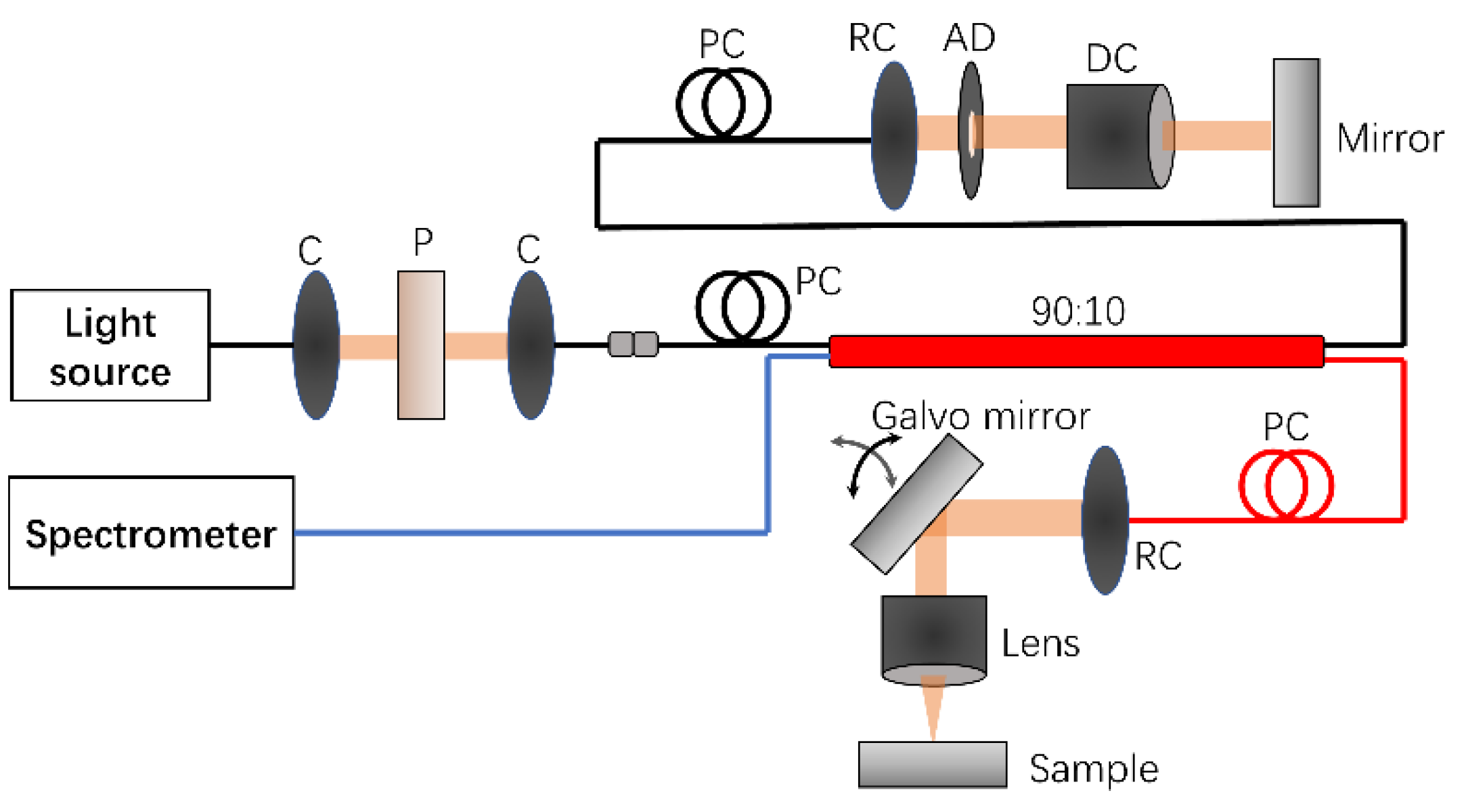
As illustrated in Figure 1, a vis-OCT system was built by adopting a spectral-domain design. In this system, a 90:10 fiber coupler was used to maximize the laser power backscattered from the sample entering the spectrometer. Fiber optics were used in our system to mimic the practical dispersion issues encountered in the widely used fiberized vis-OCT systems [34,35]. A supercontinuum laser (SuperK EXTREME, NKT photonics) was employed to provide broadband visible light with a full spectral bandwidth ranging from 493 to 705 nm. To minimize the PMD effect in the vis-OCT system, a polarizer was utilized to increase the polarization linearity of the laser source and a pair of polarization controllers was used to optimize the polarization states of the laser in two interferometric arms. Reflective collimators were used in both arms of the interferometer. A matched glass block (LSM03DC-VIS, Thorlabs) for the scan lens (LSM03-VIS, Thorlabs) was used as a dispersion compensator to minimize the dispersion imbalance between the reference and sample arms. The back-reflected laser power from the reference arm could be precisely tuned using an adjustable diaphragm. A commercialized spectrometer (CS550-600/200, Wasatch Photonics) was used with a calibrated wavenumber. The detection sensitivity of the system was measured to be ~97.8 dB with an incident power of ~1.3 mW for the sample.
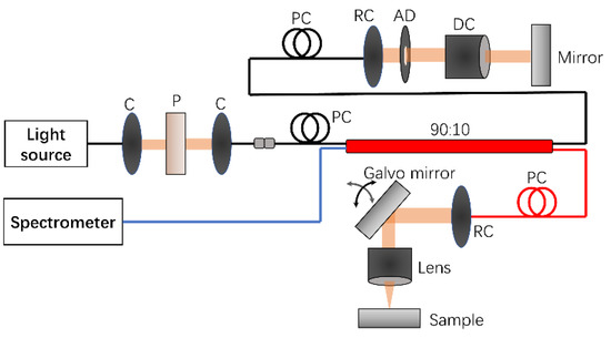
Figure 1.
The schematic of a homemade vis-OCT system. C: collimator, P: polarizer, PC: polarization controller, RC: reflective collimator, AD: adjustable diaphragm, DC: dispersion compensator.
The PSFs were measured by placing a mirror reflector in the sample arm and minimizing the power from the laser source to avoid the saturation of the spectrometer. A-lines were then acquired separately at two symmetrical locations relative to the zero OPD position by moving the mirror in the reference arm. Then, three dispersion compensation methods, including TSIF, TSMMR, and SAMMR, were used to optimize the PSFs. The TSIF [24] and SAMMR methods only required one PSF measurement, while the TSMMR method [28] needed to use two PSFs measured at symmetric locations. To validate the robustness of the SAMMR method, a glass slide (SiO2, 1 mm in thickness) was inserted in the reference arm to introduce additional dispersion imbalance into the vis-OCT system. B-scan images of a human finger and onion were acquired to test the effectiveness of the dispersion compensation method.
2.2. Dispersion Compensation Method
In this section, the theories and mathematics of the TSIF method, TSMMRmethod, and our proposed SAMMR method for compensating material dispersions in the OCT were reviewed and explained. Both the TSMMR and SAMMR methods are phase-based methods and consider the higher-order (>3rd order) dispersion in the OCT system, while the TSIF method only considers up to the third-order dispersion in this paper.
In SD-OCT, A-lines are achieved by performing fast-Fourier transform (FFT) on the linear-wavenumber spectral interferograms acquired from a spectrometer, which can be expressed by the following Equation (1):
where Ir(k) is the laser power spectrum reflected from the reference arm, Im(k) and Il(k) represent the laser power spectra backscattered from the mth and lth layers of the sample, respectively. zm is the OPD between the mth layer of the sample and the reference arm. zml is the depth difference between mth and lth layers in the sample. n(k) is the refractive index of the sample and k stands for the wavenumber of light. The first two terms in Equation (1) are known as the DC signal, which can be measured in advance. The third term is the auto-correlation component and can sometimes be ignored due to the low reflectivity of the sample and small value of zml [36]. The last term is the interference signal that contains the depth information of the sample. Here, ϕD refers to the additional phase delay caused by the material dispersion imbalance between two interferometric arms. The three methods to compensate ϕD and the dispersion imbalance are introduced in the following section.
2.2.1. Taylor Series Iterative Fitting (TSIF) Method
The TSIF method is based on the Taylor series expansion of propagation constant β(ω) at the center angular frequency ω0, as shown in Equation (2) [21]. The material dispersion-induced phase delay ϕD can be represented by the product of the propagation constant and the optical path length D, as shown in Equation (3). The linear-wavenumber spectral interferogram is then multiplied by exp(−ϕD) with the dispersion coefficients, i.e., a2 and a3, as the unknown parameters to be optimized. Usually, the zeroth and first-order dispersion coefficients, i.e., a0 and a1, are ignored since they only change the amplitude of PSF and its absolute location along the imaging depth. By maximizing a metric function of sharpness, one can deduce the second- and third-order dispersion coefficients, i.e., a2 and a3 [24,26]. Thus, ϕD can be calculated using Equation (3) and compensated. However, this method requires the optimization of the metric function, and the use of higher dispersion orders significantly increases the calculation complexity.
2.2.2. Two Symmetrical Measurements of the Mirror-Reflection (TSMMR) Method
To compensate for the higher-order dispersion, Singh et al. proposed a phase-based TSMMR method [28]. In order to extract the dispersion-induced phase delay ϕD, the spectral interferogram of PSF was acquired at two symmetrical locations relative to the zero OPD position by moving the mirror in the reference arm. Hilbert transform (HT) was then applied to derive the phase information of the two spectral interferograms after removing the DC signal (i.e., ϕ+ and ϕ−), which consisted of OPD-induced phase delays (i.e., ϕz+ and ϕz−) and a dispersion-associated phase delay (ϕD), as shown in Equations (4) and (5). ϕz+ and ϕz− refer to the phase delays caused by two symmetric OPDs in the interferometer and are considered to have the same absolute value. As shown in Equation (6), ϕD can be conveniently calculated through ϕ+ and ϕ−. This method simplifies the calculation, avoids the complicated optimization procedure in the TSIF method, and can compensate for the higher-order material dispersion. However, this method causes a potential alignment issue in the reference arm.
2.2.3. Single Arbitrary Measurement of Mirror-Reflection (SAMMR) Method
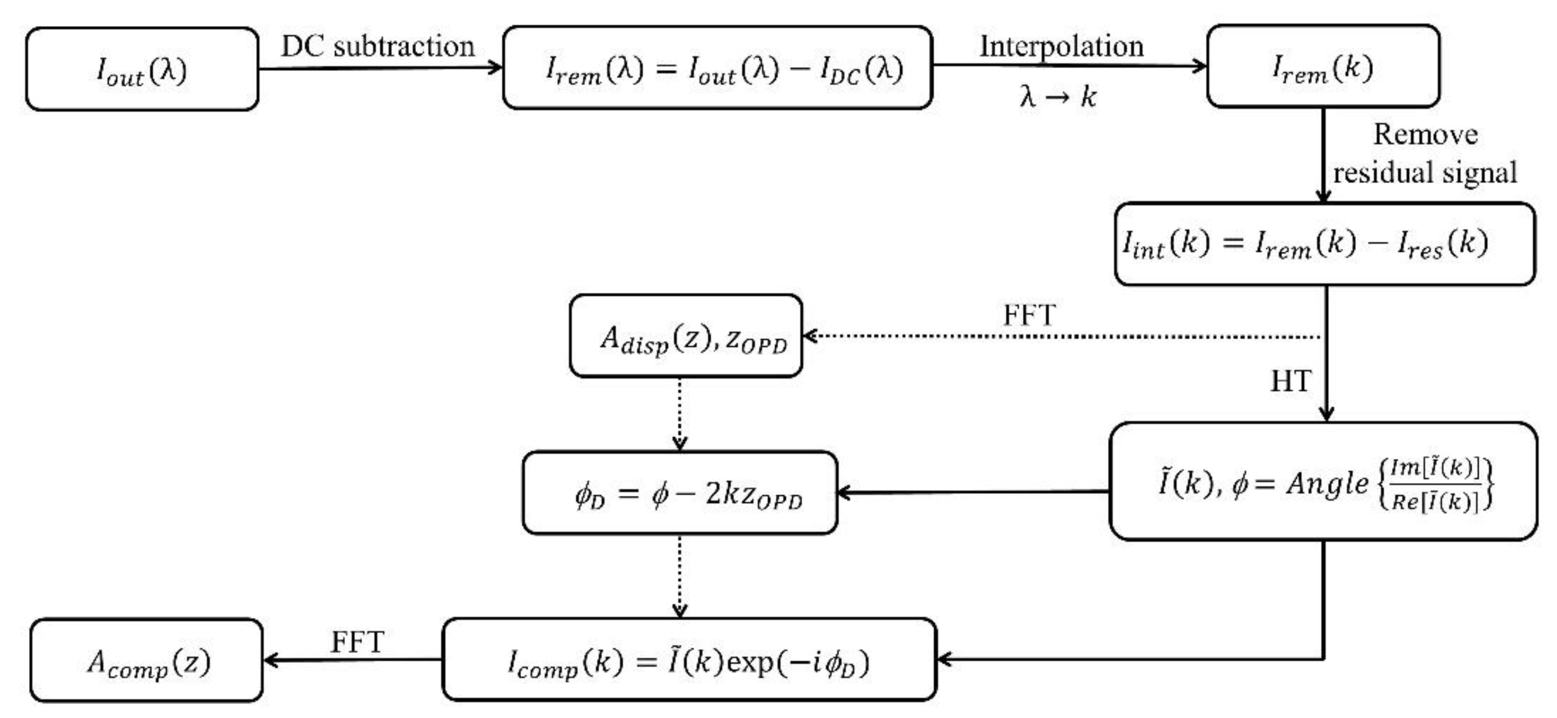
To overcome the limitations of the TSIF and TSMMR methods, we proposed the SAMMR method to directly extract and compensate ϕD. As indicated by its name, this method requires only a single measurement of a mirror reflection with arbitrary OPD within the imaging depth. Figure 2 illustrates the post-processing procedures based on the SAMMR method for dispersion compensation in the vis-OCT system. First, the DC signals measured from the reference and sample arms were subtracted from the output spectrum (Iout(λ)) acquired with a spectrometer in the wavelength domain. Then, a cubic spline interpolation on the remaining signal (Irem(λ)) was performed to achieve a spectrum of linear wavenumber distribution (Irem(k)). The interference signal Iint(k) was calculated to further remove the residual DC signal (Ires(k)), which was calculated by moving an average window over the spectrum of Irem(k). This step helped avoid the potential artificial peaks in A-lines (see Section 3.4). Then, HT was conducted to derive the complex interference signal and phase delay ϕ, as shown in Equations (7) and (8). The phase delay ϕ consisted of the phase induced by the OPD and material dispersion (Equation (9)). After determining zOPD by locating the peak position of PSF (Adisp(z)) derived from FFT of Iint(k), ϕD could be conveniently calculated in Equation (9). As shown in Equation (10), the dispersion compensated spectral interferogram (Icomp(k)) is derived and the A-line (Acomp(z)) is then achieved through the FFT of Icomp(k).
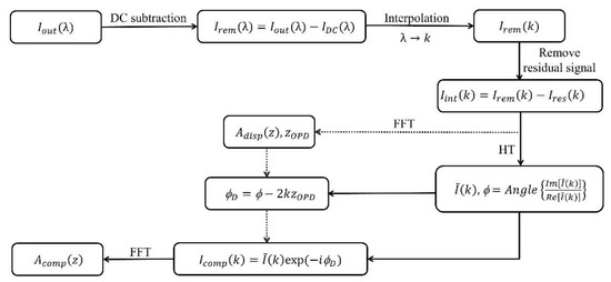
Figure 2.
Flowchart of SAMMR method-based dispersion compensation in the vis-OCT system.
3. Result
3.1. Performance Evaluation
3.1.1. Dispersion-Compensated PSFs and Their Symmetrical Properties
The original PSF measured in the vis-OCT system and dispersion-compensated PSFs using TSIF, TSMMR, and the proposed SAMMR methods are illustrated in Figure 3a. It was found that the original PSF had a broad and asymmetrical shape, and the TSIF method could barely improve the PSF due to the pronounced higher-order dispersion in the vis-OCT system. In contrast, both phase-based methods could sharpen and symmetrize the PSF, while the SAMMR method provided a PSF of better symmetry than that of the TSMMR method. As shown in Figure 3b, the symmetry of PSFs is indicated using the amplitudes of two symmetric first side lobes of the PSF. A symmetry metric is defined in Supplementary Note 1 and also indicates the better symmetrical property of PSF calculated by the SAMMR method. It was also noted that the amplitude of the main peak of PSF increased from about 89 dB (original) to approximately 100 dB (SAMMR method). The linear amplitude of PSFs with different dispersion compensation methods is also presented in Figure 3c, demonstrating the best performance of the SAMMR method.

Figure 3.
(a) Original PSF versus three dispersion-compensated PSFs using different methods. The measurement of the signal-to-noise ratio (SNR) of PSF is also illustrated. (b) Enlarged views of the PSFs shown in (a). The black dots in (b) indicate the main peaks and their first side lobes of PSFs for the calculation of PSF contrast. Note that the PSFs are shifted to different depths for clarity in (a,b). (c) Overlaid PSFs (in linear amplitude) achieved using different methods. The inset indicates the zoomed-in view of the central peak.
3.1.2. Signal-To-Noise Ratio, Full Width at Half Maximum, and Contrast of PSFs
To compare the performance of different dispersion compensation methods, we evaluated the signal-to-noise ratio (SNR, also see Figure 3a) and the full width at half maximum (FWHM) of the PSFs. As shown in Figure 4a,b, it is found that all three methods can improve the SNR of PSF; however, the TSIF and TSMMR methods can barely improve the FWHM of PSF, and the proposed SAMMR method provides both the highest SNR and the smallest FWHM of PSF. The underperformance of the TSIF method was mostly due to the significant higher-order dispersion in the vis-OCT system, while the performance of the TSMMR method was mainly manifested in the increased SNR and optimized sharpness and symmetry of PSF (also see Figure 3) with the FWHM not being improved by TSMMR.

Figure 4.
(a) SNR, (b) FWHM, and (c) contrast of original PSF versus dispersion-compensated PSFs using TSIF, TSMMR, and SAMMR methods. The error bars are the standard deviations of three measurements. The slight difference is due to the stability of the light source.
We further evaluated the contrast of PSF to demonstrate the performance of the three methods. The PSF contrast was defined by the difference between the main peak and the higher first side lobe of PSF (see Figure 3b). As shown in Figure 4c, the SAMMR method provides a PSF contrast of about 30 dB, versus around 5 dB from the TSIF method and approximately 15 dB from the TSMMR method; though, the FWHM of PSF is not improved by TSMMR. The suboptimal PSF contrast may indicate that the material dispersion is not adequately compensated by the TSIF and TSMMR methods.
3.2. Improvement of Vis-OCT Images Using the SAMMR Method
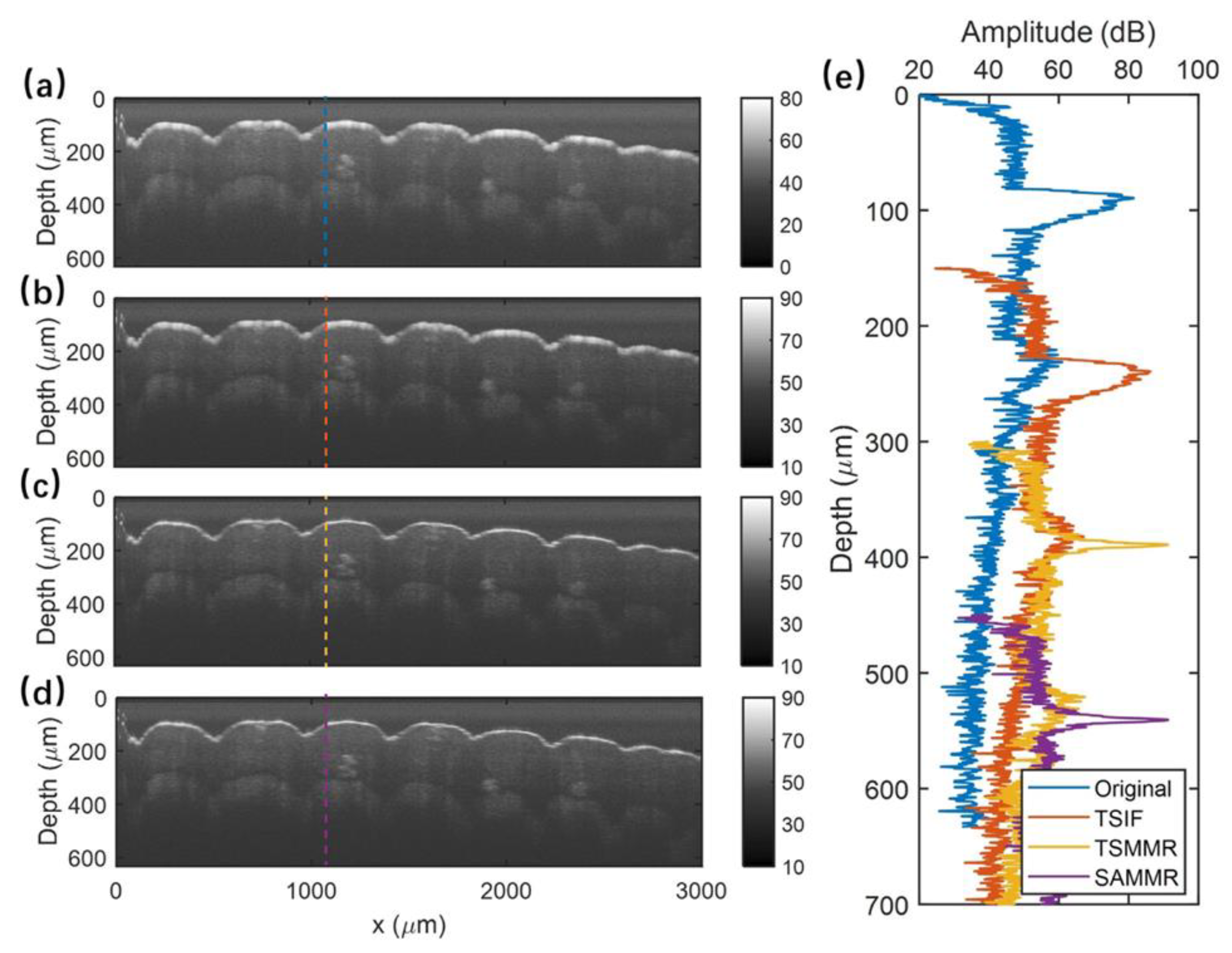
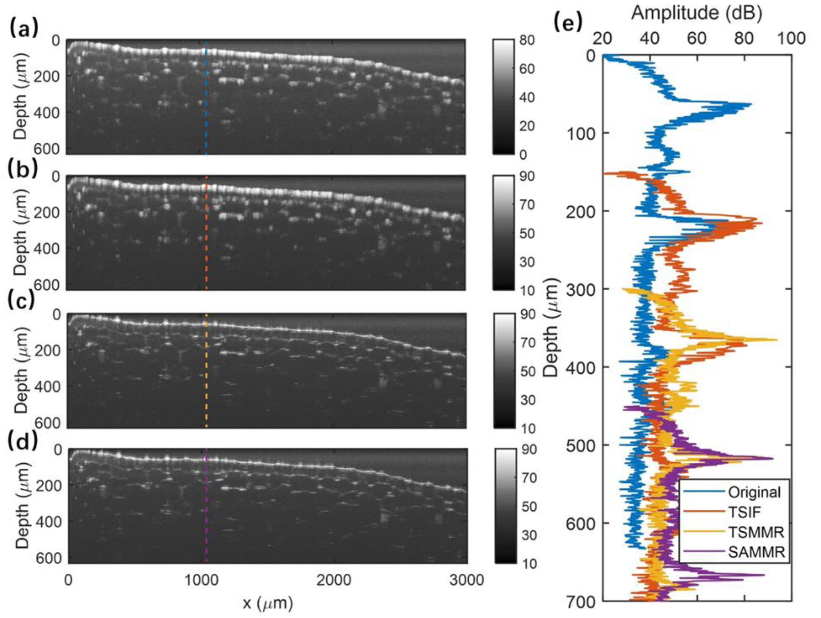
To demonstrate the performance of the SAMMR method, vis-OCT images of a human fingertip and onion were tested. We followed the post-processing procedures illustrated in Figure 2 and used the SAMMR method to extract the material dispersion-induced phase delay, i.e., ϕD, in the vis-OCT system. Then, the derived ϕD was used to compensate for the dispersions in B-frames using Equation (10). As shown in Figure 5a–d, a significantly sharpened tissue structure with an improved contrast is observed in the dispersion-compensated fingertip image versus the original one. In addition, the SAMMR and TSMMR methods offered greater improvements in the sharpness and SNR of images when compared with the TSIF method. The selected A-lines from original and dispersion-compensated B-frames were compared side-by-side and are illustrated in Figure 5e. The proposed method was further validated using the onion image. As seen in Figure 6a–d, the dispersion-compensated images clearly delineate finer cell wall structures of the onion compared to those in the original one. Additionally, the SAMMR and TSMMR methods show sharper images using the TSIF method. The sharpened cell wall structures with improved SNR values are also indicated by the spiculate peaks along the imaging depth in a representative A-line (Figure 6e).
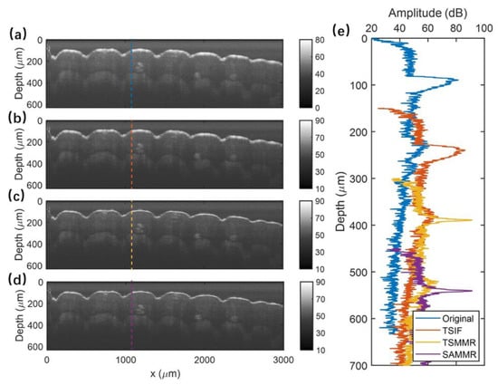
Figure 5.
(a) Original finger image versus dispersion-compensated results using (b) TSIF, (c) TSMMR, and (d) SAMMR methods; (e) comparison of a representative A-line selected in the original image and dispersion-compensated results. The SNR values of the whole image (a–d) are calculated to be 40.43, 46.58, 49.45, and 49.68 dB. Note that the PSFs in (e) are shifted to different depths for clarity.
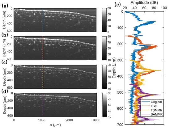
Figure 6.
Onion images of (a) original and dispersion-compensated results by (b) TSIF, (c) TSMMR, and (d) SAMMR methods; (e) selected A-lines of original, dispersion-compensated results. The SNR values of the whole image calculated from (a–d) are 45.66, 49.81, 56.53, and 55.97 dB. Note that the PSFs in (e) are shifted to different depths for clarity.
3.3. Robustness of the SAMMR Method
In this section, the robustness of the SAMMR method to compensate for the additional material and higher-order dispersions in the vis-OCT system are discussed.
3.3.1. Additional Dispersion in the Vis-OCT System
A glass slide was inserted into the reference arm to introduce an additional dispersion mismatch in the vis-OCT system and the three dispersion-compensation methods were tested for compensation effects. As seen in Figure 7, the TSIF method can barely optimize the PSF and both phase-based methods considerably improve the sharpness and symmetry of the PSF, while the SAMMR method provides the PSF with the best symmetrical property.

Figure 7.
(a) Original PSF measured with an additional glass slide in the reference arm of the vis-OCT system versus the dispersion-compensated PSFs using 3 different methods. (b) Enlarged view of the PSFs shown in (a). The black dots in (b) indicate the main peaks and their first side lobes of PSFs for the illustration of PSF contrast. Note that the PSFs are shifted to different depths for clarity in (a,b). Note that the PSFs in (a,b) are shifted to different depths for clarity.
Figure 8 further shows a detailed comparison of SNR, FWHM, and contrast of resulting PSFs from different methods with and without additional glass slides in the reference arm. It was found that the additional dispersion in the vis-OCT system led to an original PSF of a lower SNR (due to the light attenuation inside the glass slice), a wider FWHM, and a worse contrast (due to the increased dispersion mismatch in the interferometer) compared to the original PSF measured without a glass slide. Nevertheless, the SAMMR method still provided the dispersion-compensated PSF with the highest SNR, the smallest FWHM, and the best contrast than those achieved with the other two methods. Notably, a PSF of comparable FWHM and contrast could be achieved with the SAMMR method in both cases with and without additional dispersions in the vis-OCT system.

Figure 8.
The characteristics of the original PSF measured with and without additional dispersions induced by a glass slide, including (a) SNR, (b) FWHM, and (c) contrast, are compared with those of dispersion-compensated PSFs. The error bars are the standard deviations of three measurements. The slight difference is due to the stability of the light source.
3.3.2. Higher-Order Dispersion in the Vis-OCT System
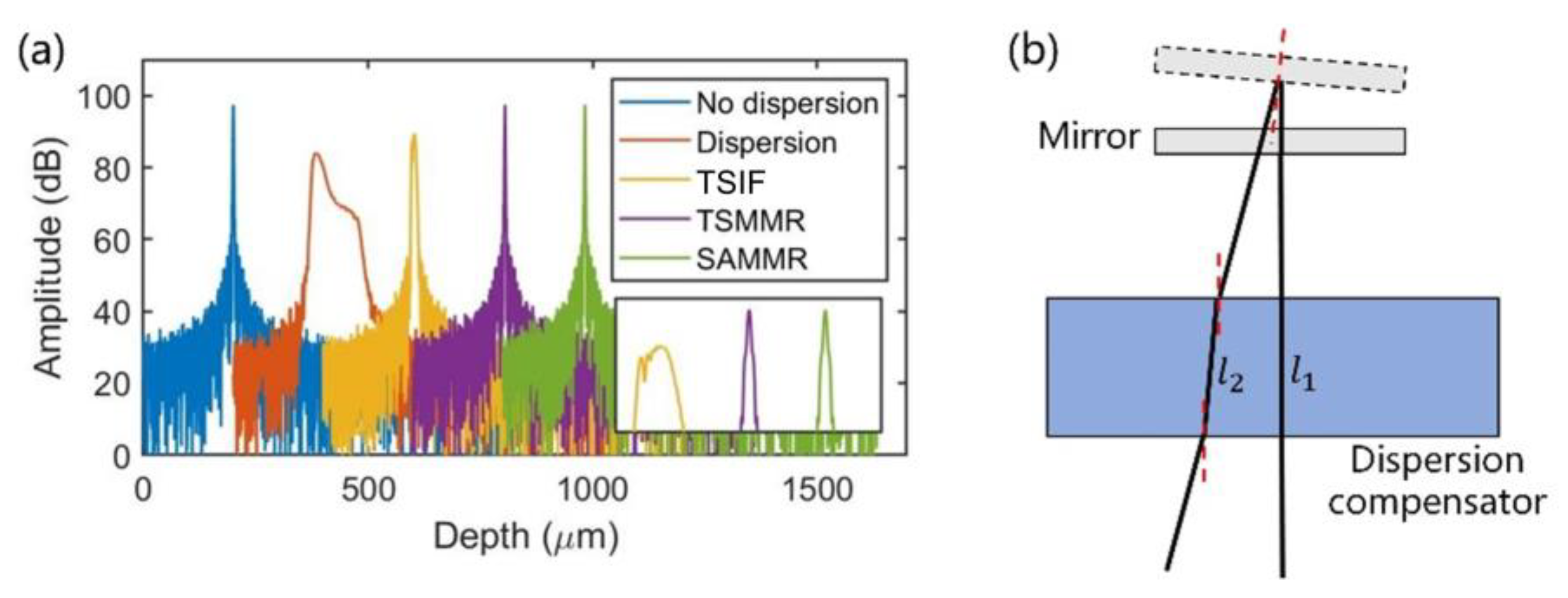
Compared to other near-infrared OCT systems, the vis-OCT system suffers more from higher-order dispersion. A second-order dispersion can easily be compensated for by matching optical materials or prism pairs in sample and reference arms. Therefore, a method capable of compensating for a higher-order dispersion is important for the vis-OCT system. As shown in Figure 9a, using the laser spectrum measured from the reference and sample arms and assuming an OPD of 200 μm (zm = 200 μm), an ideal PSF without any dispersion-induced phase delay (ϕD = 0) can be simulated by applying FFT to the interference term of Equation (1). Then, a PSF with a higher-order dispersion can be simulated by adding a phase delay (ϕD) into Equation (1). In our simulation, the phase delay (ϕD) was calculated by assigning the dispersion coefficients (in the wavenumber domain), such as a2 = 279, a3 = 121.5, a4 = 33.5, a5 = 1.7, of a SiO2 of 5 mm in length into Equation (3). Then, the three dispersion compensation methods were tested on the PSF with a higher-order dispersion. It was found that all methods could optimize the sharpness and symmetry of the PSF, while only SAMMR and TSMMR methods could compensate for all the higher-order dispersions by providing a dispersion-compensated PSF similar to the ideal one with an FWHM of 1.36 µm compared to a 8.35 µm FWHM by using the TSIF method. However, in reality, the dispersion was not restricted to the fifth-order dispersion and was not solely caused by a single material. All materials used in the system affected the dispersion, such as fiber and the lens.
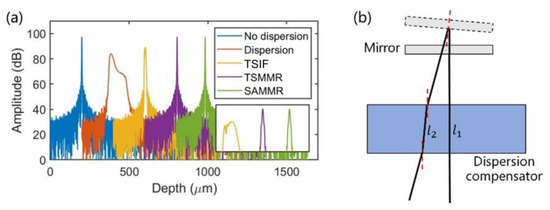
Figure 9.
(a) Simulated PSFs of the vis-OCT system with and without dispersions versus dispersion-compensated PSFs using TSIF, TSMMR, and SAMMR methods. Note that the PSFs are shifted to different depths for clarity. (b) Diagram showing the tilting of the mirror and the resulting change in the optical path in the dispersion compensator, i.e., l1 and l2.
As for the TSMMR method, the movement of the mirror in the reference arm could easily result in the tilting of the optical alignment, as shown in Figure 9b. The tilting of the mirror alters the optical path in the dispersion compensator, leading to a different dispersion-induced phase delay in two symmetric mirror measurements, a biased estimation of ϕD in the TSMMR method and potential misalignment. In contrast, the SAMMR method only required one measurement of the mirror reflection at any location within the imaging depth, which avoided the translation and tilting of the mirror in the reference arm and considerably improved its performance for the dispersion compensation.
3.4. Oscillation of Phase Delay and Artificial Peaks
It was noted that directly using the SAMMR method on a spectral interferogram caused artificial peaks in the resulting A-line. The interferogram signal after subtracting the prior measured DC signals can be expressed as below:
where the first term is the interference signal, Ir(k) and Is(k) are the reflected power spectra from the reference and sample arms, respectively, and Ires(k) stands for the residual DC signal. If the residual DC signal is not sufficiently removed, the phase delays ϕ and ϕD calculated with the SAMMR method become inaccurate (since both the resulting real and imaginary parts of HT in Equation (7) are biased) and demonstrate a characteristic oscillation feature (see blue curve in Figure 10a), leading to an artificial peak in the resulting A-line (see blue curve in Figure 10b).

Figure 10.
(a) A representative phase-delay curve (ϕD, blue) and its smoothed curve (red) calculated without removing the residual DC signal versus the phase delay calculated after a normalization step (yellow). (b) Dispersion-compensated A-lines corresponding to different phase-delay curves shown in (a). (c) The respective spectral interferograms in the normalization step, Iout(k) is the original interference signal acquired from the spectrometer, Irem(k) represents the signal after removing the prior-measured DC signals, Ires(k) is the residual DC signal, and Iint(k) is the interference signal after removing the residual DC signal.
To overcome this problem, a smoothing window was used to achieve a smoothed phase signal (see red curve in Figure 10a) for compensating for the dispersion and avoiding the artificial peak (see red curve in Figure 10b). As previously discussed in Section 2.2.3, a step by subtracting the moving average of the signal could also be used to remove the residual DC signal (Ires(k)) in the spectral interferogram (Irem(k)). This approach allowed us to derive the interference signal (Iint(k), see purple curve in Figure 10c), minimize the oscillation in the phase signal (see yellow curve in Figure 10a), and eliminate the artificial peaks in the A-line (see yellow curve in Figure 10b).
Moreover, the low-frequency oscillations in the phase curve (see yellow, red, and blue curves in Figure 10a) were mainly due to the pronounced higher-order dispersion of the vis-OCT system. This issue made it difficult to fit perfectly with Equation (3), which led to the suboptimal performance of the TSIF method in improving the PSF. These observations further verified the effectiveness and robustness of the SAMMR method for dispersion compensation in the vis-OCT system.
3.5. Application of the SAMMR Method to the 800 nm SD-OCT System
The SAMMR method was further tested on the PSFs measured in a homemade 800 nm SD-OCT system. As shown in Figure 11a,b, the TSIF method provides a better dispersion compensation in the 800 nm domain compared to its performance in the visible-light domain (see Figure 3 and Figure 7) in terms of the sharpness and symmetry of the resulting PSF. One reason for this improvement was mainly the relatively smaller higher-order dispersions in the near-infrared domain than those in the visible-light range. However, since the higher-order dispersion was not adequately compensated for in the TSIF method, the resulting PSF was still asymmetric (see Figure 11b). In contrast, the symmetrical property, SNR, FWHM, and contrast of PSF could be further improved using phase-based TSMMR and SAMMR methods (see Figure 11a,b). It is important to note that the TSMMR method suffers from the above-mentioned limitations on the resolution of the translation stage and the tilting of the mirror in the reference arm.

Figure 11.
(a) Original PSF measured in 800 nm SD-OCT system versus dispersion-compensated PSFs using TSIF, TSMMR, and SAMMR methods. (b) Enlarged view of the PSFs shown in (a). The black dots in (b) indicate the main peaks and their first side lobes of PSFs for the illustration of PSF contrast. Note that the PSFs are shifted to different depths for clarity in (a,b).
4. Discussion and Conclusions
In this paper, we proposed a generic and robust method, i.e., SAMMR, to effectively manage the pronounced dispersion mismatch in the visible-light SD-OCT system. Specifically, the proposed method took advantage of a single arbitrary measurement of mirror reflection in the sample arm to accurately extract the material dispersion-induced phase delay for dispersion compensation. This approach eliminated the potential phase errors caused by the limited mechanical accuracy of the translational stage in the TSMMR method and the tilting of optical alignment in the reference arm. Our method was able to efficiently compensate for the higher-order dispersions, and thus provided an ultrahigh axial resolution (about 1.5 μm) in vis-OCT imaging. The robustness of the SAMMR method was also validated through its effective compensation of additional material and higher-order (more than third-order) dispersions in the vis-OCT system. The effectiveness and genericity of the SAMMR method were further demonstrated in an 800 nm SD-OCT system. This generic and robust method for dispersion compensation can help to acquire an image with an optimal resolution. Moreover, the post-processing step, such as the step mentioned in Section 2.2.3, can be used to remove the DC signal and minimize artificial peaks. The calibrated high-resolution images can be further used for accurately tracking angiographic changes and visualizations of subtle structures in tissues.
Although the SAMMR method could effectively compensate for the residual dispersion imbalance existing between the reference and sample arms and help optimize the axial resolution and image quality in the vis-OCT system, there were still several limitations. First, the SAMMR method was only applicable in the OCT system, where measuring the mirror reflection in the sample arm was possible. Second, only the material dispersion in the OCT interferometer was compensated for with the SAMMR method. This method could not compensate for the dispersion induced by the sample itself, for example, the dispersion induced by vitreous humor when imaging retinal layers. Third, limited by the single measurement of PSF with a normally incident laser beam on the mirror, the material dispersion was assumed to be the same in the full field of view (FOV) of the sample arm. However, when imaging the sample at the corner of FOV, the light beam was tilted in the scan lens, leading to a longer optical path length in the scan lens and resulting in a different dispersion compared to the measurement in the middle of the FOV. To overcome these limitations, we aim to develop a digital dispersion compensation method not requiring the measurement of mirror reflection and capable of compensating for the dispersion of the sample and the spatially dependent dispersion in the sample arm in our future work.
Supplementary Materials
The following supporting information can be downloaded at: https://www.mdpi.com/article/10.3390/photonics10080892/s1, Figure S1: The calculation flowchart of TSIF method and TSMMR method; Note 1: The indicator for the symmetrical property.
Author Contributions
Conceptualization, J.W., C.X., D.C. and W.Y.; methodology, J.W. and C.X.; software, S.Z.; validation, J.W.; formal analysis, J.W.; investigation, J.W.; resources, J.W.; data curation, J.W.; writing—original draft preparation, J.W. and W.Y.; writing—review and editing, J.W., C.X., S.Z., D.C., H.Q., A.K.N.L., C.K.S.L. and W.Y.; visualization, J.W.; supervision, W.Y.; project administration, W.Y.; funding acquisition, D.C. and W.Y. All authors have read and agreed to the published version of the manuscript.
Funding
This work was supported by the Shun Hing Institute of Advanced Engineering (BME-p3-20/4720264) at the Chinese University of Hong Kong (CUHK), the Research Grants Council (RGC) of Hong Kong SAR (ECS24211020, GRF14203821, GRF14216222), the Innovation and Technology Fund (ITF) of Hong Kong SAR (ITS/240/21), the Science, Technology, and Innovation Commission (STIC) of Shenzhen Municipality (SGDX20220530111005039), and the National Science Foundation Program of China (61835015).
Institutional Review Board Statement
Not applicable.
Informed Consent Statement
Not applicable.
Data Availability Statement
Not applicable.
Conflicts of Interest
The authors declare no conflict of interest.
References
- Popescu, D.P.; Choo-Smith, L.-P.; Flueraru, C.; Mao, Y.; Chang, S.; Disano, J.; Sherif, S.; Sowa, M.G. Optical coherence tomography: Fundamental principles, instrumental designs and biomedical applications. Biophys. Rev. 2011, 3, 155–169. [Google Scholar] [CrossRef] [PubMed]
- Yun, S.; Tearney, G.; Bouma, B.; Park, B.; de Boer, J. High-speed spectral-domain optical coherence tomography at 1.3 μm wavelength. Opt. Express 2003, 11, 3598–3604. [Google Scholar] [CrossRef] [PubMed]
- Baran, U.; Choi, W.J.; Wang, R.K. Potential use of OCT-based microangiography in clinical dermatology. Skin Res. Technol. 2016, 22, 238–246. [Google Scholar] [CrossRef] [PubMed]
- Leitgeb, R.; Hitzenberger, C.; Fercher, A. Performance of fourier domain vs time domain optical coherence tomography. Opt. Express 2003, 11, 889–894. [Google Scholar] [CrossRef] [PubMed]
- Jia, Y.; Tan, O.; Tokayer, J.; Potsaid, B.; Wang, Y.; Liu, J.J.; Kraus, M.F.; Subhash, H.; Fujimoto, J.G.; Hornegger, J.; et al. Split-spectrum amplitude-decorrelation angiography with optical coherence tomography. Opt. Express 2012, 20, 4710–4725. [Google Scholar] [CrossRef]
- Pi, S.; Hormel, T.T.; Wei, X.; Cepurna, W.; Wang, B.; Morrison, J.C.; Jia, Y. Retinal capillary oximetry with visible light optical coherence tomography. Proc. Natl. Acad. Sci. USA 2020, 117, 11658–11666. [Google Scholar] [CrossRef]
- Mogensen, M.; Thrane, L.; Jørgensen, T.M.; Andersen, P.E.; Jemec, G.B.E. OCT imaging of skin cancer and other dermatological diseases. J. Biophotonics 2009, 2, 442–451. [Google Scholar] [CrossRef]
- Blatter, C.; Weingast, J.; Alex, A.; Grajciar, B.; Wieser, W.; Drexler, W.; Huber, R.; Leitgeb, R.A. In situ structural and microangiographic assessment of human skin lesions with high-speed OCT. Biomed. Opt. Express 2012, 3, 2636–2646. [Google Scholar] [CrossRef]
- Guagliumi, G.; Sirbu, V. Optical coherence tomography: High resolution intravascular imaging to evaluate vascular healing after coronary stenting. Catheter. Cardiovasc. Interv. 2008, 72, 237–247. [Google Scholar] [CrossRef]
- Adams, D.C.; Hariri, L.P.; Miller, A.J.; Wang, Y.; Cho, J.L.; Villiger, M.; Holz, J.A.; Szabari, M.V.; Hamilos, D.L.; Harris, R.S.; et al. Birefringence microscopy platform for assessing airway smooth muscle structure and function in vivo. Sci. Transl. Med. 2016, 8, 359ra131. [Google Scholar] [CrossRef]
- Yuan, W.; Brown, R.; Mitzner, W.; Yarmus, L.; Li, X. Super-achromatic monolithic microprobe for ultrahigh-resolution endoscopic optical coherence tomography at 800 nm. Nat. Commun. 2017, 8, 1531. [Google Scholar] [CrossRef] [PubMed]
- Luo, Y.; Cui, D.; Yu, X.; Bo, E.; Wang, X.; Wang, N.; Braganza, C.S.; Chen, S.; Liu, X.; Xiong, Q.; et al. Endomicroscopic optical coherence tomography for cellular resolution imaging of gastrointestinal tracts. J. Biophotonics 2018, 11, e201700141. [Google Scholar] [CrossRef] [PubMed]
- Yuan, W.; Feng, Y.; Chen, D.; Gharibani, P.; Chen, J.D.Z.; Yu, H.; Li, X. In vivo assessment of inflammatory bowel disease in rats with ultrahigh-resolution colonoscopic OCT. Biomed. Opt. Express 2022, 13, 2091–2102. [Google Scholar] [CrossRef] [PubMed]
- Jiao, S.; Ruggeri, M. Polarization effect on the depth resolution of optical coherence tomography. J. Biomed. Opt. 2008, 13, 060503. [Google Scholar] [CrossRef]
- Yuan, W.; Mavadia-Shukla, J.; Xi, J.; Liang, W.; Yu, X.; Yu, S.; Li, X. Optimal operational conditions for supercontinuum-based ultrahigh-resolution endoscopic OCT imaging. Opt. Lett. 2016, 41, 250–253. [Google Scholar] [CrossRef]
- Shu, X.; Beckmann, L.; Zhang, H.F. Visible-light optical coherence tomography: A review. J. Biomed. Opt. 2017, 22, 121707. [Google Scholar] [CrossRef]
- Yuan, W.; Chen, D.; Sarabia-Estrada, R.; Guerrero-Cázares, H.; Li, D.; Quiñones-Hinojosa, A.; Li, X. Theranostic OCT microneedle for fast ultrahigh-resolution deep-brain imaging and efficient laser ablation in vivo. Sci. Adv. 2020, 6, eaaz9664. [Google Scholar] [CrossRef]
- Yuan, W.; Thiboutot, J.; Park, H.-C.; Li, A.; Loube, J.; Mitzner, W.; Yarmus, L.; Brown, R.H.; Li, X. Direct Visualization and Quantitative Imaging of Small Airway Anatomy In Vivo Using Deep Learning Assisted Diffractive OCT. IEEE Trans. Biomed. Eng. 2022, 70, 238–246. [Google Scholar] [CrossRef]
- Wachulak, P.; Bartnik, A.; Fiedorowicz, H. Optical coherence tomography (OCT) with 2 nm axial resolution using a compact laser plasma soft X-ray source. Sci. Rep. 2018, 8, 8494. [Google Scholar] [CrossRef]
- Akcay, A.C.; Rolland, J.P.; Eichenholz, J.M. Spectral shaping to improve the point spread function in optical coherence tomography. Opt. Lett. 2003, 28, 1921–1923. [Google Scholar] [CrossRef]
- Pan, L.; Wang, X.; Li, Z.; Zhang, X.; Bu, Y.; Nan, N.; Chen, Y.; Wang, X. Depth-dependent dispersion compensation for full-depth OCT image. Opt. Express 2017, 25, 10345–10354. [Google Scholar] [CrossRef] [PubMed]
- Yaqoob, Z.; Wu, J.; Yang, C. Spectral domain optical coherence tomography: A better OCT imaging strategy. Biotechniques 2005, 39, S6–S13. [Google Scholar] [CrossRef] [PubMed]
- Kho, A.; Srinivasan, V.J. Compensating spatially dependent dispersion in visible light OCT. Opt. Lett. 2019, 44, 775–778. [Google Scholar] [CrossRef] [PubMed]
- Wojtkowski, M.; Srinivasan, V.J.; Ko, T.H.; Fujimoto, J.G.; Kowalczyk, A.; Duker, J.S. Ultrahigh-resolution, high-speed, Fourier domain optical coherence tomography and methods for dispersion compensation. Opt. Express 2004, 12, 2404–2422. [Google Scholar] [CrossRef] [PubMed]
- Cense, B.; Nassif, N.A.; Chen, T.C.; Pierce, M.C.; Yun, S.-H.; Park, B.H.; Bouma, B.E.; Tearney, G.J.; de Boer, J.F. Ultrahigh-resolution high-speed retinal imaging using spectral-domain optical coherence tomography. Opt. Express 2004, 12, 2435–2447. [Google Scholar] [CrossRef]
- Yasuno, Y.; Hong, Y.; Makita, S.; Yamanari, M.; Akiba, M.; Miura, M.; Yatagai, T. In vivo high-contrast imaging of deep posterior eye by 1-μm swept source optical coherence tomography and scattering optical coherence angiography. Opt. Express 2007, 15, 6121–6139. [Google Scholar] [CrossRef]
- Luo, S.; Holland, G.; Mikula, E.; Bradford, S.; Khazaeinezhad, R.; Jester, J.V.; Juhasz, T. Dispersion compensation for spectral domain optical coherence tomography by time-frequency analysis and iterative optimization. Opt. Contin. 2022, 1, 1117–1136. [Google Scholar] [CrossRef]
- Singh, K.; Sharma, G.; Tearney, G.J. Estimation and compensation of dispersion for a high-resolution optical coherence tomography system. J. Opt. 2018, 20, 025301. [Google Scholar] [CrossRef]
- Makita, S.; Fabritius, T.; Yasuno, Y. Full-range, high-speed, high-resolution 1-µm spectral-domain optical coherence tomography using BM-scan for volumetric imaging of the human posterior eye. Opt. Express 2008, 16, 8406–8420. [Google Scholar] [CrossRef]
- Uribe-Patarroyo, N.; Kassani, S.H.; Villiger, M.; Bouma, B.E. Robust wavenumber and dispersion calibration for Fourier-domain optical coherence tomography. Opt. Express 2018, 26, 8081–9094. [Google Scholar] [CrossRef]
- Attendu, X.; Ruis, R.M. Simple and robust calibration procedure for k-linearization and dispersion compensation in optical coherence tomography. J. Biomed. Opt. 2019, 24, 056001. [Google Scholar] [CrossRef]
- Ahmed, S.; Le, D.; Son, T.; Adejumo, T.; Ma, G.; Yao, X. ADC-Net: An Open-Source Deep Learning Network for Automated Dispersion Compensation in Optical Coherence Tomography. Front. Med. 2022, 9, 864879. [Google Scholar] [CrossRef] [PubMed]
- Yang, D.; Guo, W.; Cheng, T.; Wei, Z.; Xu, B. Artificial neural network (ANN) for dispersion compensation of spectral domain–Optical coherence tomography (SD-OCT). Instrum. Sci. Technol. 2022, 50, 560–576. [Google Scholar] [CrossRef]
- Chong, S.P.; Zhang, T.; Kho, A.; Bernucci, M.T.; Dubra, A.; Srinivasan, V.J. Ultrahigh resolution retinal imaging by visible light OCT with longitudinal achromatization. Biomed. Opt. Express 2018, 9, 1477–1491. [Google Scholar] [CrossRef] [PubMed]
- Song, W.; Zhou, L.; Zhang, S.; Ness, S.; Desai, M.; Yi, J. Fiber-based visible and near infrared optical coherence tomography (vnOCT) enables quantitative elastic light scattering spectroscopy in human retina. Biomed. Opt. Express 2018, 9, 3464–3480. [Google Scholar] [CrossRef]
- Chan, K.K.H.; Tang, S. High-speed spectral domain optical coherence tomography using non-uniform fast Fourier transform. Biomed. Opt. Express. 2010, 1, 1309–1319. [Google Scholar] [CrossRef]
Disclaimer/Publisher’s Note: The statements, opinions and data contained in all publications are solely those of the individual author(s) and contributor(s) and not of MDPI and/or the editor(s). MDPI and/or the editor(s) disclaim responsibility for any injury to people or property resulting from any ideas, methods, instructions or products referred to in the content. |
© 2023 by the authors. Licensee MDPI, Basel, Switzerland. This article is an open access article distributed under the terms and conditions of the Creative Commons Attribution (CC BY) license (https://creativecommons.org/licenses/by/4.0/).

