Article

Fiber Coupled High Power Nd:YAG Laser for Nondestructive Laser Cleaning

1
Laser Institute, Qilu University of Technology (Shandong Academy of Sciences), 3501 Daxue Road, Jinan 250100, China
2
CAS Key Laboratory of Separation Sciences for Analytical Chemistry, Dalian Institute of Chemical Physics, Chinese Academy of Sciences, Dalian 116023, China
*
Author to whom correspondence should be addressed.
Photonics 2023, 10(8), 901; https://doi.org/10.3390/photonics10080901
Submission received: 5 July 2023 / Revised: 22 July 2023 / Accepted: 1 August 2023 / Published: 3 August 2023
(This article belongs to the Section Lasers, Light Sources and Sensors)

Abstract

:
In this study, a fiber coupled high power side-pumped Nd:YAG laser system for laser cleaning is presented. Based on the two-rod structure and two stages amplifiers, the maximum average output power of 783 W with corresponding pulse energy of 52 mJ at 15 kHz has been achieved. The fiber coupling efficiencies after the master oscillator, one stage amplifier and two stages amplifiers reach to 99%, 98.3% and 94%, respectively. A laser cleaning machine prototype composed of the master oscillator and one stage amplifier with an average output power of greater than 500 W has been developed and achieved better nondestructive cleaning effect for thermal control coating removal compared with commercial fiber laser cleaning machines. This study provides a new method for developing high power laser sources for nondestructive laser cleaning equipment.

1. Introduction

Laser cleaning technology has developed rapidly in recent years [1,2,3,4,5,6,7]. Compared with chemical, mechanical grinding and ultrasonic cleaning methods, laser cleaning technology is an environmentally friendly method, which is characterized by high efficiency, good stability and little damage to the substrate [2]. Laser cleaning technology has been widespread applied in metal surface treatment such as removing rust, dirt, paint, coatings and oil [8,9,10,11]. In order to avoid the unnecessary injury of substrates, flat-top beam spot with uniform spatial intensity distribution is more desirable for non-destructive laser cleaning compared with typical TEM00 Gaussian transverse mode [12,13]. Fiber lasers have been demonstrated as a good choice for kilowatt level output power due to the intrinsic merits of excellent heat dissipation, good beam quality, high efficiency and compact size. However, the strong nonlinear effects of pulsed fiber lasers, such as stimulated Raman scattering (SRS), stimulated Brillouin scattering (SBS) and self-phase-modulation (SPM), are unavoidable [14]. The repetition frequency of high power pulsed fiber lasers always reaches to hundreds kilohertz, which declines the pulse energy and peak power. Moreover, near TEM00 Gaussian beam shape with concentration intensity distribution of fiber lasers is not suitable for non-destructive laser cleaning. Laser diode (LD) side-pumped acousto-optic (AO) Q-switched Nd:YAG (Nd3+:Y3Al5O12) lasers in multi transversal mode operation are suitable to generate high power (>500 W), high repetition rate (>10 kHz) laser radiations with beam spot of near flat-top spatial intensity distribution [15,16,17,18], which is an ideal laser source choice for non-destructive laser cleaning. Assisted with the energy transmitting fiber, high power Nd:YAG laser radiations can be delivered in long distance with low loss. Therefore, the scope of laser cleaning application is widely expanded. Y. B. Wang et al. demonstrated a high power fiber coupled AO Q-switched 1 kW Nd:YAG laser, which provided a new method for developing kilowatt-class Nd:YAG lasers based on master oscillator power-amplifier (MOPA) configuration [17]. However, the fiber coupling efficiency is not stable and varies with pump current due to the defocusing of the MOPA system by low-order aberration. D. W. Yang built a fiber coupled MOPA Nd:YAG laser system with over 400 W average output power, which is used in paint removal and mold cleaning applications [18]. However, there is an unstable zone that leads to a small variation in laser output power. Two identical Nd:YAG rods connection configuration is a typical method of improving output power, because the thermally induced birefringence can be efficiently compensated with a 90° quartz rotator [19,20]. Combined with the MOPA system, the output power can be further scaled up.
Nd:YAG laser has been proven to be a promising, effective and low-cost type of laser source for laser cleaning application [21,22,23,24,25]. Palomar et al. demonstrated the effective removal of dirt from pure silver products with a nanosecond Q-switched Nd:YAG laser [21]. Zhu et al. used an acousto-optic Q-switched nanosecond Nd:YAG laser to remove the oxide film from 5A12 aluminum alloy surface and demonstrated that the optimal cleaning effect was obtained with an average power of 280 W, a repetition rate of 10 kHz, a pulse duration of 84 ns and an overlapping rate of 70% [22]. Ren et al. explored a pulsed Nd:YAG laser system and studied the effects of laser cleaning process on the surface of an aerospace aluminum alloy (AA2024) and Q345 steel [23,24] and found that the laser energy density was the critical parameter for cleaning quality. By optimizing the laser energy density, effective cleaning removal of impurities and oxide film on the surface of AA2024 and Q345 without ablation pits can be achieved. Hala Afifi performed a comparative study between two laser wavelengths (1064 and 532 nm) of a Nd:YAG laser about removing stains of pigments used on archaeological cartonnage [25], which identified that the 1064 nm Nd:YAG laser performed better compared with the 532 nm laser. The high-power nanosecond Nd:YAG laser with a high peak power and a wide adjustment range of laser energy can improve cleaning efficiency. It is suitable for removing thick multilayer coatings and metal oxide film, which have strong adhesive force with the substrate.
Thermal control coating is widely used in spacecrafts to withstand huge temperature ranges under the rigorous space environment to keep the stable working condition of precise instruments. For the damaged or disabled coating, it is necessary to remove the original coating for subsequent recoat. Laser cleaning provides a new method for effective removal of unwanted thermal control coating layers with little damage in base materials. To the best of our knowledge, thermal control coating removal using the laser cleaning technique has not been applied.
Though versatile types of laser sources have been performed in laser cleaning, there are few studies about specific high power pulsed Nd:YAG laser sources and the comparison of laser cleaning effect between Nd:YAG lasers and fiber lasers. In this work, a high-power pulsed laser source for laser cleaning applications was obtained from an LD side-pumped Nd: YAG AO Q-switched laser. The maximum average output power is 367 W, 525 W and 796 W after the master oscillator, one stage amplifier and two stages amplifiers, respectively. A pulsed laser cleaning machine based on the laser head prototype has been demonstrated. A comparative study of the thermal control coating removal behavior by laser cleaning has been investigated based on the pulsed Nd:YAG laser and fiber laser.

2. Experimental Setup

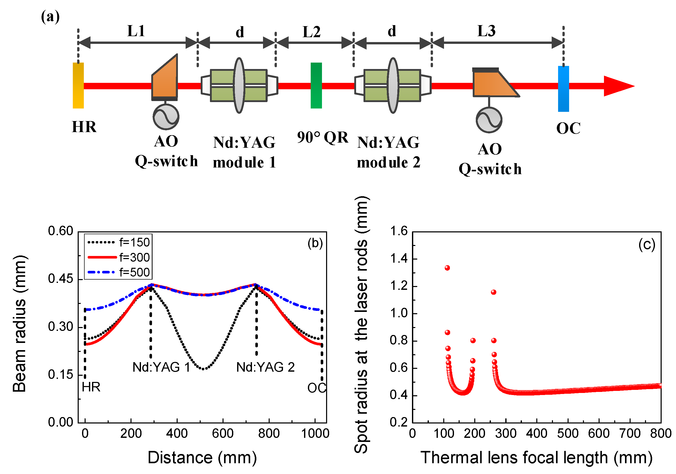
Laser Resonator and Amplifier System Configuration

The experimental configuration of LD side-pumped AO Q-switched Nd:YAG laser is shown in Figure 1. The laser system includes a master oscillator laser and two amplifier units. The laser resonator of the master oscillator consists of two identical LD side-pumped Nd:YAG modules. Each of the Nd:YAG module contains a Nd:YAG rod with the diameter of 5 mm and the length of 130 mm. Thirty-five 40 W diode bars at central wavelength of 808 nm are distributed in a five-fold symmetry around the Nd:YAG rod. In order to compensate the thermal birefringence of two Nd:YAG modules, a 90° quartz rotator (φ25.4 × 14.4 mm) is placed between them. For the pulsed operation, two water-cooling acousto-optic Q-switches (26th of CETC) with perpendicular acousto field are placed near each Nd:YAG rod. The transmission of output coupler for master oscillator is 40% at 1.06 μm. The overall geometrical cavity length of the master oscillator is about 1.03 m. An identical Nd:YAG module is used as the first stage amplifier. For the second stage amplifier, the laser gain medium is a Nd:YAG rod with a diameter of 6 mm and a length of 160 mm. The Nd3+doping concentration is 0.6 at.% for all Nd:YAG rods. Both the Nd:YAG modules are cooled by flowing water with the temperature of 24 °C. Both the end faces of all the Nd:YAG rods are coated with antireflection (AR) films at 1064 nm. The average output power is measured using a water-cooling power meter (W-1500-D40-HPB, Laserpoint Inc., Vimodrone, Italy). The pulse waveform is detected using a digital oscilloscope (RTO10141, 1 GHz bandwidth, Rohde & Schwarz GmbH & Co. KG, Muenchen, Germany) and a photo-diode (PDA10A-EC, Thorlabs Inc., Newton, NJ, USA).

3. Theoretical Analysis of Laser Resonator

The stability of the laser resonator is affected strongly by the thermal effect of laser gain media at high power operation. In the theoretical analysis process, the Nd:YAG rod is simplified as a combination of a thin lens in the center and two symmetrical segments. The thermal focal length decreases as the thermal effect becomes stronger when the pump power increases. Based on the ABCD propagation matrix theory, the roundtrip ABCD matrix for the laser resonator by making the HR mirror as the reference plane can be expressed as follows:
M = A B C D = M H R · L 1 · M r o d · M f · M r o d · L 2 · M r o d · M f · M r o d · L 3 · M O C · L 3 · M r o d · M f · M r o d ] · [ L 2 · M r o d · M f · M r o d · L 1
where [MHR] and [MOC] are ray matrix of the HR mirror and output coupler, respectively. In the flat-flat resonator, [MHR] and [MOC] can be written as:
M H R = M O C = 1 0 0 1
[L1] and [L3] represent the ray propagation matrices for the free space between the HR mirror and Nd:YAG module 1, and between Nd:YAG module 2 and the output coupler, respectively. [L2] represents the ray propagation matrices for the distance between two Nd:YAG modules. [Mrod] represents the ray propagation matrix of a side pumped Nd:YAG rod considering the refractive index of Nd:YAG and can be written as
M r o d = 1 d / 2 n 0 1
where d is the length of a Nd:YAG rod, and n is the refractive index of Nd:YAG. [Mf] represents the ray propagation matrix of the thermal focal lens of a Nd:YAG rod and can be written as
M f = 1 0 1 / f r o d 1
where frod is the thermal lens focal length of a laser rod. The spot beam radius of Gaussian fundamental mode at reference plane can be expressed as
ω = λ π B 1 ( A + D 2 ) 2 1 / 2
where A, B, D are the parameters in Formula (1), and λ is the laser wavelength in this resonator. By changing the position of the reference plane, the relationship between the simulation fundamental mode radius with different intracavity position can be achieved. By fixing the reference plane at the center of the Nd:YAG rod, the simulation result for the calculated fundamental mode radius at the center of the laser rod as a function of thermal focal length can be obtained.
Figure 2b shows the simulated fundamental mode beams in the resonator at different thermal focal length (f) of the Nd:YAG rods according to the ABCD propagation matrix. The simulation results suggest that the beam spot radius at Nd:YAG rods is relatively larger compared with other locations in the resonator. The large beam size can effectively avoid optical damage in Nd:YAG rods. Figure 2c shows the variation of the simulation fundamental mode radius at Nd:YAG rod center versus the thermal focal length. There are two stable zones in the whole pump region. As f > 300 mm, the spot radius is nearly constant at the bottom of simulation curve, indicating good thermal stability of the current resonator design. The wide stability zone of the resonator is very important for reducing the output power fluctuation at high pump power level, as the cooling water temperature always fluctuates, resulting in the thermal focal length variation. With further increasing pump power, the resonator moves to the unstable zone and gradually enters the second stable zone as f, varying from 100 to 200 mm. As the second stable zone is relative narrow, as shown in Figure 2c, the laser should be maintained in the first stable zone for good thermal stability.

4. Results and Discussion

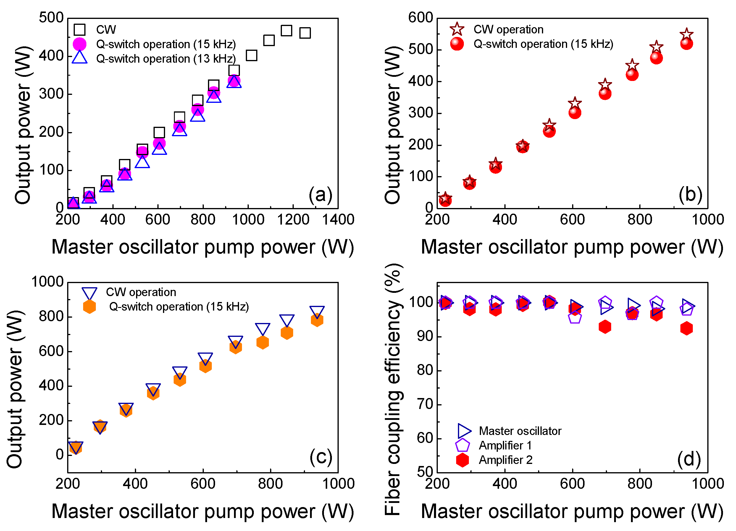
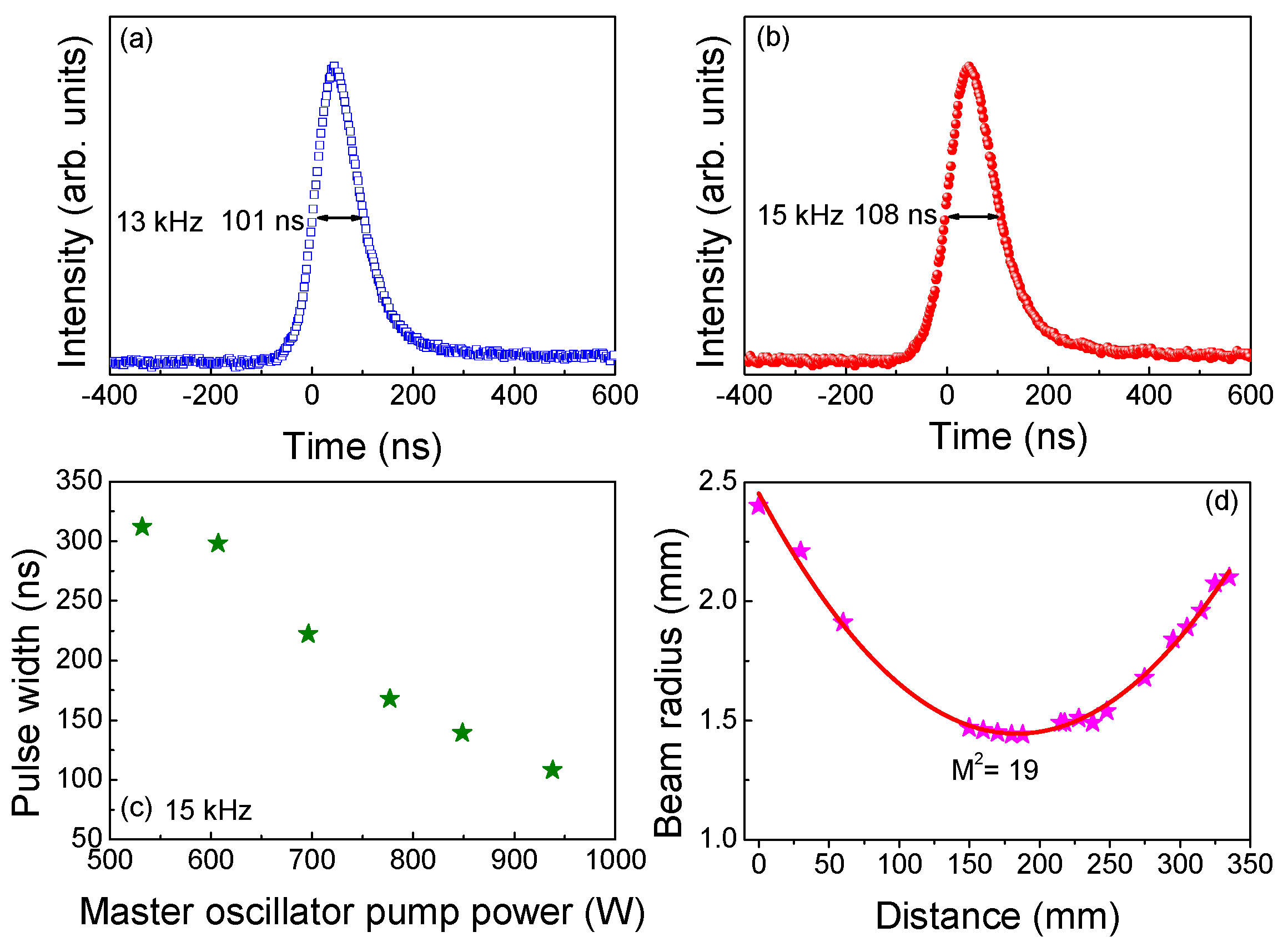
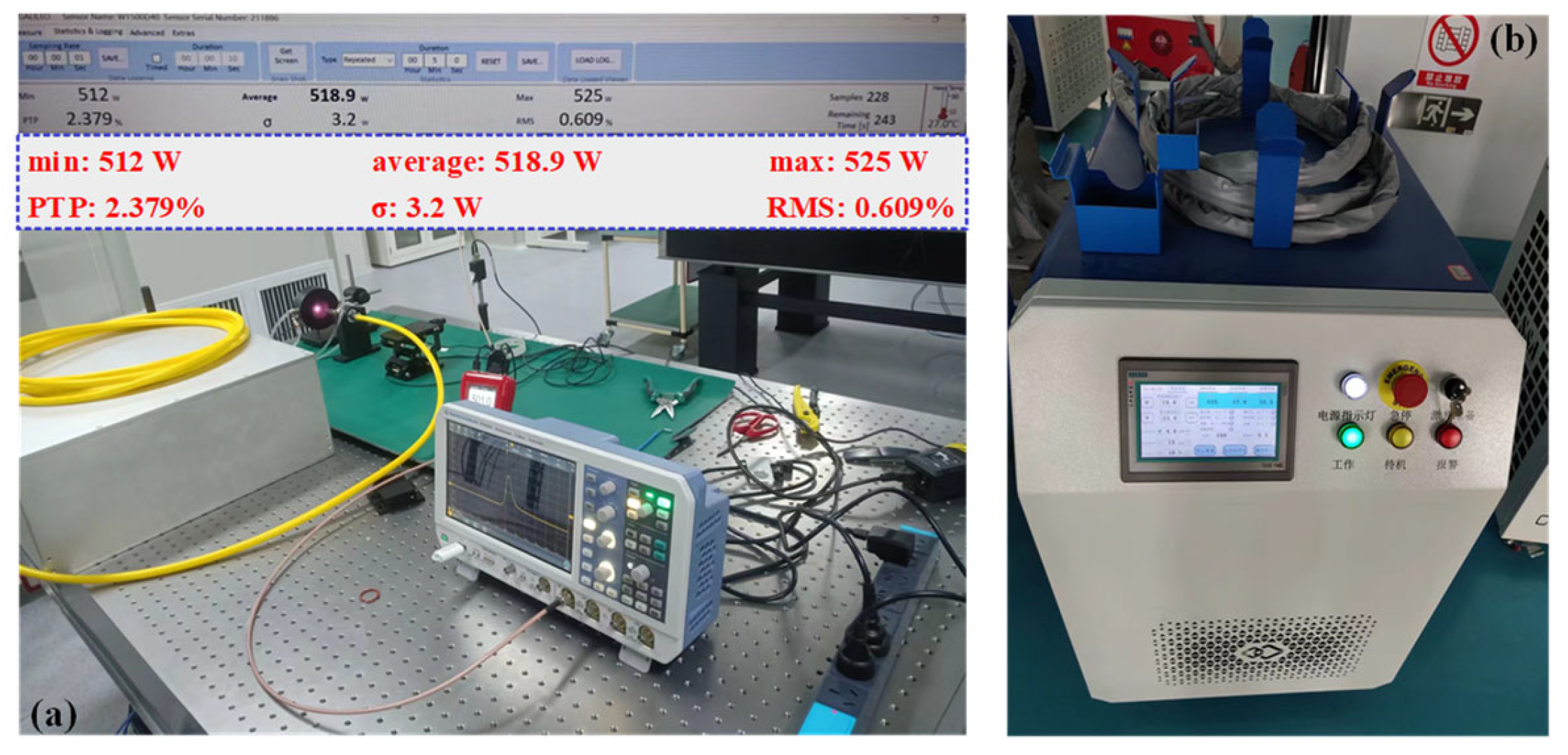
4.1. Laser Performance of the LD Side-Pumped AO Q-Switched Nd:YAG Laser System

Figure 3a shows the output power of the master oscillator versus the pump power for continuous wave (CW) and Q-switch operation. The output power increases linearly with pump power with a slope efficiency of 45%. When the pump power is increased to 1170 W, the maximum CW output power of 467 W is obtained with an optical–optical efficiency of 40%. The corresponding electro-optical conversion efficiency is 18.4%. With further increasing pump power, the laser resonator enters an unstable area, and the output power begins to decline. For pulsed operation, the laser performance is investigated at the repetition frequency of 13 and 15 kHz. When the pump power exceeds 1000 W, the pulse trains becomes unstable because the AO Q-switch cannot shut off completely at high power level. Therefore, the maximum pump power is limited to 938 W for good pulse stability as well as good thermal stability. As the frequency is increased from 13 kHz to 15 kHz, the average output power increases from 329 to 336 W.
For further power scaling up, an identical Nd:YAG module with the master oscillator is served as the first stage amplifier. In order to provide enough laser cleaning efficiency and simultaneously avoid unwanted coating damage, an optimum repetition frequency of 15 kHz is selected. Figure 3b,c show the amplified output power as the function of the master oscillator pump power. The pump power of amplifier 1 is set to 666.75 W. The maximum amplified output power of 548 W in CW operation and 520 W in Q-switch operation are obtained, respectively. The optical–optical conversion is 34%. For additional power scaling up, the second stage amplifier with φ6 × 140 mm Nd:YAG rod is used. The pump power of amplifier 2 is set to 1900 W. The maximum output power is amplified to 838 W in CW operation. For the Q-switch operation, the maximum average output power is 783 W. The extract efficiency of two stage amplifiers is calculated to be approximately 62% and 67%, respectively. The total optical-to-optical conversion efficiency of the Nd:YAG laser system is 24%. The corresponding electro-optical conversion efficiency is 11.5%. Note that the current pump power is far from the maximum available pump power for the master oscillator (Pmax = 1517 W) and first-stage amplifier (Pmax = 759 W) considering the long-term stability and keeping enough thermal management redundancy. Further promotion to kilowatt-level average output power and megawatt-level peak power will be expected by improving the pump power of amplifier modules.
Figure 3d shows the fiber coupling efficiency of the Nd:YAG laser for Q-switch operation versus master oscillator pump power. The laser beam is focused into the water-cooled transmitting energy fiber with a 400 μm core diameter (QBH connector) through a plano-convex fused silica lens of 50 mm focus length. After passing through the fiber, the maximum average output power of the master oscillator, one stage amplifier and two stages amplifiers is 332 W, 510 W and 731 W at 15 kHz, respectively. The corresponding fiber coupling efficiency is calculated to be 99%, 98.3% and 94%, respectively. The fiber coupling efficiency degradation of two stage amplifier may be caused by spherical phase aberration introduced by the thermal effects leading to the deterioration of beam quality [17].
Typical temporal pulse profiles in full width at half maximum (FWHM) corresponding to the maximum average output power at 13 and 15 kHz are shown in Figure 4a,b, respectively. With further scaling up in pump power from 535 W to 938 W at 15 kHz, the pulse width was shortened from 300 ns to 108 ns. As the frequency was increased from 13 kHz to 15 kHz, the pulse width broadened from 101 ns to 108 ns. The corresponding maximum pulse energy and peak power for the master oscillator were 25.3 mJ, 250 kW and 22.4 mJ, 207 kW at 13 and 15 kHz, respectively. For the amplifier system, the maximum pulse energy and peak power for one stage amplifier and two stages amplifier were 35 mJ, 321 kW and 52 mJ, 483 kW at 15 kHz. At the maximum output power, the focused beam spot radius at different locations was measured using the 90/10 knife-edge method along the beam propagation axis [26]. The variation of focused laser beam radius at different positions is shown in Figure 4d. A plano-convex lens with a focal length of 400 mm was employed to focus the laser radiation to create a waist. An adjustable thin knife was used to partially block the laser radiation. A power meter was placed behind the adjustable thin knife to measure the laser power with 10% and 90% occlusion ratio. By moving the adjustable thin knife with a translational stage, the laser beam radius at different locations was obtained. Based on the hyperbolic fitting, the beam quality factor (M2) of the laser system was calculated to be 19 on the x axis, which can be regarded as the M2 value of the whole beam. The M2 value can be further improved by inserting apertures, but the output power may decline. No transverse-mode selection device was utilized in the resonator considering the long stability and the whole size of the laser system.
The master oscillator and the first stage amplifier were designed into modules, which can be easily assembled for laser cleaning equipment. The dimensions of the laser head is 684 mm × 504 mm × 206 mm with the master oscillator and one stage amplifier. The laser system maintained good average output power stability. Average output power stability of 0.609% (RMS) at 15 kHz is obtained. Figure 5a shows the prototype model of the MOPA Nd:YAG laser system, which consists of the master oscillator and the first stage amplifier. The MOPA Nd:YAG laser system with 400 μm fiber is installed into a laser cleaning machine, as shown in Figure 5b.
Table 1 summarizes laser characteristics with maximum output power operation of this work and some analogous typical high power Nd:YAG lasers. Compared with previous works, the results obtained in this work are superior in terms of M2 value, which is mainly attributed to the design of dual-rod structure and long length resonator. The M2 value of slightly lower than 20 is desirable for high fiber coupling efficiency and meanwhile keeping uniform intensity distribution of the output laser beam spot. This result indicates that the combination of dual-rod structure and a MOPA configuration is an attractive design for a high average power Nd:YAG laser system with good beam quality.

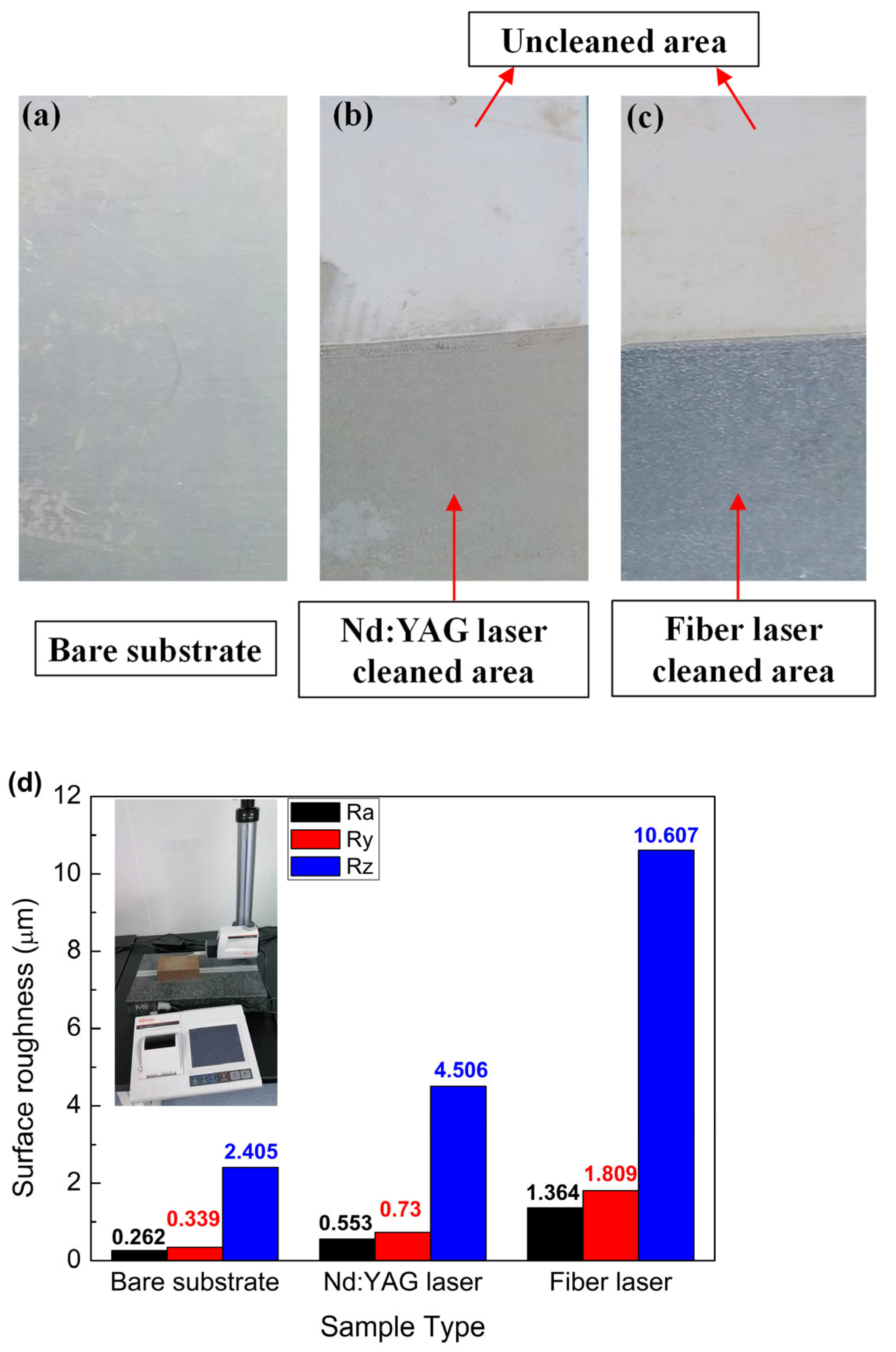
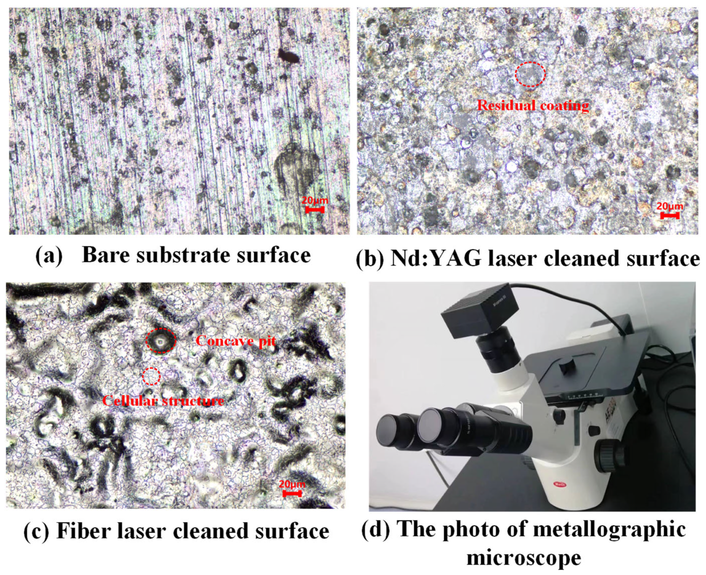
4.2. Comparison of Thermal Control Coating Removal between Nd:YAG and Fiber Laser Cleaning Machine

Here, laser cleaning machines based on the Nd:YAG laser and a commercial high power pulsed Yb3+-doped double-clad fiber laser (Maxphotonics Co., Ltd., Shenzhen, China) were adopted to remove thermal control coating from an aluminum substrate’s surface. The fiber laser beam was delivered through 200 μm core diameter optical fiber. The aluminum plates covered with thermal control coating were selected as the experimental samples. Figure 6 shows the experimental setup of the laser cleaning system, which consists of a high-power pulsed laser (Nd:YAG laser or fiber laser), a laser cleaning head, a water chiller and a KUKA industrial robot. The laser beam was moved by a single-axis optical scanning galvanometer and focused on the sample surface by a field lens with a focal length of 160 mm. The experimental parameters are illustrated in Table 2. The surface properties were measured with a roughness tester (SJ-410, MITUTOYO Inc., Kawasaki, Japan). A metallographic microscope (AE2000MET, Motic Inc., Barcelona, Spain) was carried out to examine the microstructure of substrate before and after laser cleaning.
In the experiment, the scanning speed and the overlapping rate are fixed to 20 mm/s and 10%, respectively. The peak power intensity required for efficient coating removal are approximately 3.9 × 10⁴ kW/cm2 and 4.6 × 10⁴ kW/cm2 for the Nd:YAG laser and fiber laser, respectively. Figure 7a shows the photo of aluminum substrate plate without thermal control coating. Figure 7b,c show the photos of the samples cleaned with the Nd:YAG laser and fiber laser, respectively. The samples are cleaned in half of the area of the plates for the exhibition of laser cleaning effect. As shown in Figure 7, the thermal control coating removal with the fiber laser cleaning appears more uniform, bright and smooth compared with the Nd:YAG laser treatment. But the substrate surface roughness cleaned by the fiber laser degraded apparently in comparison of the bare substrate plate. In contrast, the coating removal with the Nd:YAG laser produces relatively small variation of surface roughness compared with the bare substrate plate. Moreover, the surface color of the samples cleaned by the Nd:YAG laser is more similar to the original substrate material.
In order to examine the damage performance of the laser cleaning process for the substrates, a metallographic microscope was performed to observe the microstructure and characterization of the samples. Figure 8 shows the surface macrographs of the bare substrate plate and the samples after laser cleaning treatment in a magnification of 200. Most of the coating on the surface of plates was efficiently removed by both the Nd:YAG laser and fiber laser. However, as viewed under an microscopy, there still existed a thin layer of residual coating particles remaining on several area of the plates after using the Nd:YAG laser, which can be removed easily by rubbing with organic solvent. For the fiber laser treatment, there existed several metal crystalline cellular structures and deep concave pits as shown in Figure 8, which indicated the substrate damage emerging. The substrate damage in the coating removal process was mainly due to thermal effect-induced strain and stress [3,30]. The fiber laser with good beam quality was expected to possess a Gaussian spatial profile, which exhibited peak intensity at the center of the beam and an exponential decay towards the edge. The Gaussian intensity distribution of laser beams brought high temperature gradients in the laser working area, which contributed to the metal substrate damage. The wide pulse width (about 500 ns) of the fiber laser also contributed to the thermal ablative damage to the substrate. Therefore, the Nd:YAG laser in multi transversal mode operation with a flat-top spatial intensity distribution was more favorable for non-destructive laser cleaning application for thermal control coating removal [12,13].

5. Conclusions

Here, the AO Q-switched Nd: YAG MOPA laser system with high power for laser cleaning was presented. The maximum average output power was 336 W for master oscillator at 15 kHz. The corresponding pulse energy and peak power were 22.4 mJ and 207 kW, respectively. The average output power of 520 W at 15 kHz was obtained after the first side-pumped Nd:YAG amplifier module. With the two stage amplifiers, the average output power was further scalable to 783 W. The corresponding pulse energy and peak power were 35 mJ, 321 kW and 52 mJ, 483 kW, respectively. The corresponding fiber coupling efficiency reached to nearly 99%, 98.3% and 94%, respectively. The prototype laser head, consisting of a laser oscillator and first stage amplifier, was developed and incorporated into a laser cleaning system for nondestructive cleaning of spacecraft thermal control coatings. Compared with the pulsed fiber laser, the pulsed Nd:YAG laser with a top hat beam intensity distribution is more favorable for non-destructive laser cleaning application.

Author Contributions

Conceptualization, X.W.; methodology, X.M. and J.W.; investigation, Y.R.; W.C., supervision. All authors have read and agreed to the published version of the manuscript.

Funding

This work is supported by the National Natural Science Foundation of China (22104139), Jinan “20 New Universities” Funding Project (202228019) and the Qilu University of Technology (Shandong Academy of Sciences), Education and Industry Integration Pilot Project (2022PY045).

Institutional Review Board Statement

Not applicable.

Informed Consent Statement

Not applicable.

Data Availability Statement

The data in this study are available from the corresponding author upon reasonable request.

Conflicts of Interest

The authors declare no conflict of interest.

References

  1. Madhukar, Y.K.; Mullick, S.; Shukla, D.K.; Kumar, S.; Nath, A.K. Effect of laser operating mode in paint removal with a fiber laser. Appl. Surf. Sci. 2013, 264, 892–901. [Google Scholar] [CrossRef]
  2. Zhu, G.D.; Xu, Z.H.; Jin, Y.; Chen, X.; Yang, L.J.; Xu, J.; Shan, D.B.; Chen, Y.B.; Guo, B. Mechanism and application of laser cleaning: A review. Opt. Laser. Eng. 2022, 157, 107130. [Google Scholar] [CrossRef]
  3. Razab, M.; Noor, A.M.; Jaafar, M.S.; Abdullah, N.H.; Suhaimi, F.M.; Mohamed, M.; Adam, N.; Yusuf, N. A review of incorporating Nd:YAG laser cleaning principal in automotive industry. J. Radiat. Res. Appl. Sci. 2018, 11, 393–402. [Google Scholar] [CrossRef] [Green Version]
  4. Chen, T.; Wang, W.J.; Tao, T.; Pan, A.F.; Mei, X.S. Multi-scale micro-nano structures prepared by laser cleaning assisted laser ablation for broadband ultralow reflectivity silicon surfaces in ambient air. Appl. Surf. Sci. 2020, 509, 145182. [Google Scholar] [CrossRef]
  5. Li, W.Q.; Su, X.; Gu, J.Y.; Jin, Y.; Xu, J.; Guo, B. Removal Mechanisms and Microstructure Characteristics of Laser Paint Stripping on Aircraft Skin Surface. Photonics 2023, 10, 96. [Google Scholar] [CrossRef]
  6. Gao, K.; Xu, J.J.; Zhu, Y.; Zhang, Z.Y.; Zeng, Q.S. Study on the Technology and Mechanism of Cleaning Architectural Aluminum Formwork for Concrete Pouring by High Energy and High Repetition Frequency Pulsed Laser. Photonics 2023, 10, 242. [Google Scholar] [CrossRef]
  7. Fang, C.H.; Hu, T.; Pu, Z.H.; Li, P.; Wu, T.; Jiang, J.B.; Sun, A.Q.; Zhang, Y. Effect of Laser Cleaning Parameters on Surface Filth Removal of Porcelain Insulator. Photonics 2023, 10, 269. [Google Scholar] [CrossRef]
  8. Yue, L.Y.; Wang, Z.B.; Li, L. Modeling and simulation of laser cleaning of tapered micro-slots with different temporal pulses. Opt. Laser Technol. 2013, 45, 533–539. [Google Scholar] [CrossRef]
  9. Shi, T.Y.; Wang, C.M.; Mi, G.Y.; Yan, F. A study of microstructure and mechanical properties of aluminum alloy using laser cleaning. J. Manuf. Process. 2019, 42, 60–66. [Google Scholar] [CrossRef]
  10. Tian, Z.; Lei, Z.L.; Chen, Y.B.; Chen, C.; Zhang, R.C.; Chen, X.; Bi, J.; Sun, H.R. Inhibition Effectiveness of Laser-Cleaned Nanostructured Aluminum Alloys to Sulfate-reducing Bacteria Based on Superwetting and Ultraslippery Surfaces. ACS Appl. Bio Mater. 2020, 3, 6131–6144. [Google Scholar] [CrossRef]
  11. Wei, P.Y.; Chen, Z.H.; Wang, D.; Zhang, R.N.; Li, X.Y.; Zhang, F.; Sun, K.L.; Lei, Y.C. Effect of laser cleaning on mechanical properties of laser lap welded joint of SUS310S stainless steel and 6061 aluminum alloy. Mater. Lett 2021, 291, 129549. [Google Scholar] [CrossRef]
  12. Wazen, P. 80 W average power of Q-switched ND:YAG laser with optical fibre beam delivery for laser cleaning application. J. Cult. Herit. 2000, 1, S125–S128. [Google Scholar] [CrossRef]
  13. Choubey, A.; Vishwakarma, S.C.; Vachhani, D.M.; Singh, R.; Misra, P.; Jain, R.K.; Arya, R.; Upadhyaya, B.N.; Oak, S.M. Study and development of 22 kW peak power fiber coupled short pulse Nd:YAG laser for cleaning applications. Opt. Laser. Eng. 2014, 62, 69–79. [Google Scholar] [CrossRef]
  14. Ouyang, D.Q.; Chen, Y.W.; Liu, M.Q.; Wu, X.; Yang, Q.G.; Xu, F.H.; Zhong, M.R.; Lue, Q.T.; Ruan, S.C. 310 W picosecond laser based on Nd:YVO4 and Nd:YAG rod amplifiers. Opt. Laser Technol. 2022, 148, 107668. [Google Scholar] [CrossRef]
  15. Furuta, K.; Kojima, T.; Fujikawa, S.; Nishimae, J. Diode-pumped 1 kW Q-switched Nd: YAG rod laser with high peak power and high beam quality. Appl. Opt. 2005, 44, 4119–4122. [Google Scholar] [CrossRef] [Green Version]
  16. Nicklaus, K.; Hoefer, M.; Hoffmann, D.; Luttmann, J.; Wester, R.; Poprawe, R. MOPA with kW average power and multi MW peak power: Experimental results, theoretical modeling and scaling limits. Solid State Lasers XV Technol. Devices 2006, 6100, 610016. [Google Scholar]
  17. Wang, Y.B.; Zhang, Z.Y.; Liang, H.; Qu, S.C.; Gao, J.C.; Lin, X.C. Fiber coupled 1 kW repetitively acousto-optic Q-switched cw-pumped Nd:YAG rod laser. Opt. Laser Technol. 2019, 116, 139–143. [Google Scholar] [CrossRef]
  18. Yang, D.W.; Wang, Y.; Ren, Y. Fiber-coupled high-power diode-pumped solid-state lasers for laser cleaning. Solid State Lasers XXIX Technol. Devices 2020, 11259, 112590T. [Google Scholar]
  19. Guo, L.; Yang, Y.L.; Xu, H.P.; Kong, H.; Lv, G.R.; Wen, J.Q.; Bian, J.T.; Ye, Q.; Sun, X.Q.; Yang, K.J. High power linearly polarized diode-side-pumped Nd:YAG laser based on an asymmetric flat-flat resonator with the variable working point. Opt. Commun. 2022, 520, 128453. [Google Scholar] [CrossRef]
  20. Liu, H.Y.; Bian, Q.; Bo, Y.; Zong, N.; Peng, Q.J. Compact 200 W level linearly polarized microsecond-pulse Nd:YAG oscillator with nearly diffraction-limited beam quality. Appl. Opt. 2022, 61, 5614–5618. [Google Scholar] [CrossRef]
  21. Palomar, T.; Oujja, M.; Llorente, I.; Barat, B.R.; Canamares, M.V.; Cano, E.; Castillejo, M. Evaluation of laser cleaning for the restoration of tarnished silver artifacts. Appl. Surf. Sci. 2016, 387, 118–127. [Google Scholar] [CrossRef] [Green Version]
  22. Zhu, G.D.; Wang, S.R.; Cheng, W.; Wang, G.Q.; Liu, W.T.; Ren, Y. Investigation on the Surface Properties of 5A12 Aluminum Alloy after Nd: YAG Laser Cleaning. Coatings 2019, 9, 578. [Google Scholar] [CrossRef] [Green Version]
  23. Ren, Y.; Wang, L.M.; Li, J.F.; Cheng, W.; Ma, X.Q. The Surface Properties of an Aviation Aluminum Alloy after Laser Cleaning. Coatings 2022, 12, 273. [Google Scholar] [CrossRef]
  24. Ren, Y.; Wang, L.M.; Ma, M.L.; Cheng, W.; Li, B.L.; Lou, Y.X.; Li, J.F.; Ma, X.Q. Stepwise Removal Process Analysis Based on Layered Corrosion Oxides. Materials 2022, 15, 7559. [Google Scholar] [CrossRef]
  25. Afifi, H.A.M.; Abdel-Ghani, M.; Mahmoud, R.; Alkallas, F.H.; Trabelsi, A.B.G.; Mostafa, A.M. Comparative Study between First and Second Harmonics of a Nd:YAG Laser for Cleaning Manifestation Damages That Appeared in Pigments Used on Archaeological Cartonnage. Micromachines 2023, 14, 1415. [Google Scholar] [CrossRef]
  26. Hodson, N.; Weber, H. Optical Resonators: Fundamentals; Springer: Berlin/Heidelberg, Germany, 1997; pp. 423–494. [Google Scholar]
  27. Yuan, X.D.; Zhang, L.; Hu, Z.G.; Liu, Y.N.; Zhang, Z.Y.; Yu, H.J.; Wu, P.; Wang, L.R.; Zhao, W.F.; Wang, Y.B.; et al. High power fiber-coupled acousto-optically Q-switched 532 nm laser with a side-pumped Nd:YAG laser module. J. Opt. Technol. 2017, 84, 373–376. [Google Scholar] [CrossRef]
  28. Wang, Y.B.; Zhang, Z.Y.; Liang, H.; Gao, J.C.; Qu, S.C.; Lin, X.C. Exploration on hold-off capacity of high power repetitively acousto-optic Q-switched Nd:YAG rod laser. Optik 2019, 185, 161–167. [Google Scholar] [CrossRef]
  29. Singh, A.; Sharma, S.K.; Mukhopadhyay, P.K.; Bindra, K.S. 260 W of average green beam generation by intracavity frequency-doubled acousto-optic Q-Switched Nd:YAG laser. J. Opt.-India 2019, 48, 512–519. [Google Scholar] [CrossRef]
  30. Li, Y.G.; Yuan, Z.G.; Wang, J.; Xu, Q. Laser-induced damage characteristics in fused silica surface due to mechanical and chemical defects during manufacturing processes. Opt. Laser Technol. 2017, 91, 149–158. [Google Scholar] [CrossRef]
Figure 1. (a) Schematic diagram of the LD side-pumped AO Q-switched Nd:YAG laser. (b) The photo of experimental setup.
Photonics 10 00901 g001
Figure 2. (a) The simplified resonator schematic diagram of the LD side-pumped AO Q-switched Nd:YAG laser. (b) Simulated cavity fundamental mode beam radius at different location for different thermal focal length. (c) The variation of simulated spot beam radius at the laser rods versus the thermal focal length.
Photonics 10 00901 g002
Figure 3. Output power and fiber coupling efficiency of the Nd:YAG laser system versus master oscillator pump power. (a) Master oscillator; (b) one stage amplifier; (c) two stages amplifier; (d) fiber coupling efficiency of master oscillator, one stage amplifier and two stage amplifiers.
Photonics 10 00901 g003
Figure 4. The pulse performance of the Nd:YAG laser system. (a) Typical temporal pules profile at 13 kHz; (b) typical temporal pules profile at 15 kHz; (c) the pulse width variation versus the master oscillator pump power; (d) measured beam quality factor at maximum output power.
Photonics 10 00901 g004
Figure 5. (a) The MOPA Nd:YAG laser system with a transmitting energy fiber; (b) the photo of laser cleaning machine.
Photonics 10 00901 g005
Figure 6. The photo of the automatic laser cleaning system.
Photonics 10 00901 g006
Figure 7. (a) The photo of the bare substrate plate without thermal control coating; (b,c) thermal control coating removal by use of the Nd:YAG laser (b) and fiber laser (c); (d) the photo of roughness tester and the measured roughness value of different samples.
Photonics 10 00901 g007
Figure 8. (ac) Surface micrographs of the bare substrate plate (a), laser cleaning effect by the Nd:YAG laser (b) and fiber laser (c) in a magnification of 200; (d) the photo of metallographic microscope.
Photonics 10 00901 g008
Table 1. Summary of output parameters of high power AO Q-switched Nd:YAG lasers a.
Laserλ (nm)Pav (W)R. R (kHz)Ep (mJ)Pp (kW)tp (ns)M2ηf (%)Ref.
Nd:YAG/AO10647831552.24831081994This work
Nd:YAG/AO10644471044.75887622 [18]
Nd:YAG/AO106410222051.150010235.482–92[17]
Nd:YAG/AO/LBO532165208.2551.6160 90.3%[27]
Nd:YAG/AO10644081527.23447924.6 [28]
Nd:YAG/AO/LBO5322601814.41987335 [29]
a λ—laser emission wavelength, Pav—maximum average output power, R. R—repetition rate, Ep—pulse energy, Pp—peak power, t—pulse width, ηf—fiber coupling efficiency.
Table 2. Working parameters of the lasers a.
Type of Laserλ (nm)Dcorre (μm)Pave (W)R. R (kHz)Ep (mJ)tp (ns)Pp (kW)
Nd:YAG laser10644005001533.3108308
Fiber laser10702005001145.550091
a λ—laser wavelength, Pav—average output power, R. R—repetition rate, Ep—pulse energy, Pp—peak power, tp—pulse width.
Disclaimer/Publisher’s Note: The statements, opinions and data contained in all publications are solely those of the individual author(s) and contributor(s) and not of MDPI and/or the editor(s). MDPI and/or the editor(s) disclaim responsibility for any injury to people or property resulting from any ideas, methods, instructions or products referred to in the content.

