Abstract
In order to capture true-color information of distant targets under extremely low light, a large-format low-light imaging system is designed based on an RGB filter wheel. By decomposing the system indicators, this study proposes a method for acquiring low-light true-color images using a large-aperture, low-distortion optical lens combined with an RGB filter wheel capable of multi-line sequential exposure. The optical field segmentation is achieved using a four-panel optical reflective prism, and the images from four high-sensitivity SCOMS detectors are stitched together to form a composite image. The working principle of the system is explained, and the low-light imaging capability is thoroughly evaluated. The dimensions and rotation speed of the filter wheel are then calculated in detail, ensuring accurate synchronization of the filter wheel’s speed and exposure time. The calculation method for the parameters of the four-panel reflective prism structure is investigated, mathematical expressions for the geometric parameters of the prism assembly are provided, and a prism assembly suitable for four-way spectral separation is designed. Based on the research and design results, a large-swath-width, low-light true-color imaging system is developed that is suitable for an environmental illuminance of 0.01 lux. The system achieves a ground pixel resolution of 0.5 m (at an altitude of 5 km) and an effective image resolution of 4 K × 4 K, and is capable of accurately reproducing target color information. Laboratory and field flight tests verified that the large-swath-width images obtained by the imaging system are clear, with high contrast and resolution. After image fusion and spectral registration, the color images exhibit full saturation and high fidelity, meeting the requirements of low-light true-color imaging under airborne conditions. The design methodology of this low-light imaging system can serve as a reference for the development of airborne low-light imaging equipment.
1. Introduction
Under natural conditions, the ground illuminance scattered by sunlight during the day is approximately 10,000 lux. At night, the illuminance on the ground under a full moon at the zenith is around 0.1 lux, while on a clear night with only faint starlight, the illuminance is approximately 0.01 lux [1,2]. Environments with ground illuminance below 0.1 lux are generally referred to as low-light environments. Information acquisition in low-light environments is of significant importance in both military and civilian applications [3]. The experience of several contemporary regional wars bears out that large-scale attacks or critical battles often occur at night. Obtaining comprehensive battlefield intelligence throughout the day is a key factor for success in modern warfare. To adapt to the unpredictability of war and increase the temporal and spatial coverage of operations, night vision technology has become essential. Currently, aerial reconnaissance night vision technology primarily falls into two categories: low-light imaging technology and infrared thermal imaging technology. Both have the advantages of high reconnaissance concealment and adaptability for imaging throughout the day. Compared to infrared thermal imaging, low-light imaging technology can achieve imaging results close to daylight in nighttime environments and offers the advantage of high resolution. As a result, it has received increasing attention in recent years [4].
Traditional low-light night vision systems generally provide monochromatic grayscale images (each pixel on the image has only two possible values or grayscale levels). Monochromatic images are less sensitive to human eyes, and targets that require color differentiation can be easily overlooked. This directly affects the detection and identification of targets in military reconnaissance. Color information can effectively improve image contrast because human eyes have high sensitivity, target recognition rates, and reaction speeds for color images. Color information in low-light environments can be divided into pseudo-color and true color [5,6]. Pseudo-color information mainly utilizes image fusion from different wavelength bands, such as a fusion between low-light images and infrared images or of low-light images with near-infrared spectral images. However, such fusion images cannot accurately reflect the true color information of objects and may affect target interpretation. Low-light true-color imaging technology uses filtering techniques to spectrally divide visible light at night, and then utilizes high-sensitivity detectors to capture images in different wavelength bands. These images are subsequently fused to obtain low-light night vision images with true colors that are similar or close to those observed under daylight conditions. True-color low-light images can effectively enhance the richness and depth of information acquisition at night, increasing the reliability of target interpretation [7,8].
In order to obtain large-swath-width, high-resolution true-color images in low-light environments, this study focuses on a low-light true-color system based on an RGB filter wheel. The basic approach involves using a telephoto lens with a large aperture, performing multi-line sequential exposure using an RGB filter wheel to separate the reflected light from the target into three spectral bands, and then synthesizing real-time images to obtain true-color images. In addition, to achieve a large coverage area in a single image, the optical stitching method of multiple detector optical fields is investigated. The performance of the developed low-light true-color imaging system is validated, revealing that all system indicators meet the requirements. The low-light imaging effect is excellent, with vibrant colors and high fidelity, indicating that the system can meet the demands of airborne low-light true-color imaging.
2. Principles of the System Design
2.1. Main Technical Indicators
In accordance with the actual application requirements, the key technical indicators of the airborne low-light imaging system are as follows:
- Minimum illuminance: 0.01 lux.
- Ground pixel resolution: ≤0.5 m (@5 km).
- Imaging swath width: 2 km × 2 km (@5 km).
- Spectral range: visible light, RGB.
- Weight: ≤10 kg.
The indicators also specify the aircraft platform and the system’s capacity to operate during daylight. The high-speed aircraft platform limits the integration time of the imaging system. In addition, the system’s requirement to work in both day and night low-light conditions necessitates a wide dynamic range. These factors impose high demands on the overall performance of the low-light imaging system.
2.2. System Working Principle
Figure 1 shows the working principle of the large-format low-light imaging system based on an RGB filter wheel. The target light signals in low-light environments pass through an optical lens, variable aperture, RGB filter wheel, prism assembly, and high-sensitivity CMOS imaging detectors. After photoelectric conversion, the three primary color images of the target are obtained. The collected three-color images are fused in real time using a field-programmable gate array (FPGA) to form a true-color target image. Image stitching is also performed to generate high-resolution output with a large coverage area. The lens features a long focal length, large aperture, and low distortion, meeting the requirements for long-range high-resolution imaging. The optical system incorporates a variable aperture, which can vary between F2 and F20 (with the minimum aperture selected so as to not sacrifice system resolution and to maintain a certain level of imaging contrast). This ensures a wide dynamic range and the ability to perform imaging in low-light nighttime environments as well as in daylight [9]. The RGB filter wheel is equipped with three monochrome filters that can be rotated around its axis to switch between filters and acquire the three primary color images of the target [10]. The field-of-view stitching component is primarily used for optical path division, achieving imaging field-of-view stitching for multiple detectors to meet the requirements of large-format imaging [11,12,13].
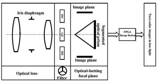
Figure 1.
System working principle.
2.3. Optical System
The detection chip is the core of the low-light imaging system. We performed a comparison of technologically mature high-sensitivity CMOS detection chips. On this basis, a high-sensitivity SCMOS detector with a pixel size of 11 × 11 μm was ultimately chosen. This detector has large pixels and high detection sensitivity. Its main performance parameters are listed in Table 1.

Table 1.
SCMOS sensor parameters.
Based on the input of system technical indicators and the selected parameters of the high-sensitivity CMOS detector, the design parameters of the optical system were determined, as shown in Table 2.
Table 2.
Optical system parameters.
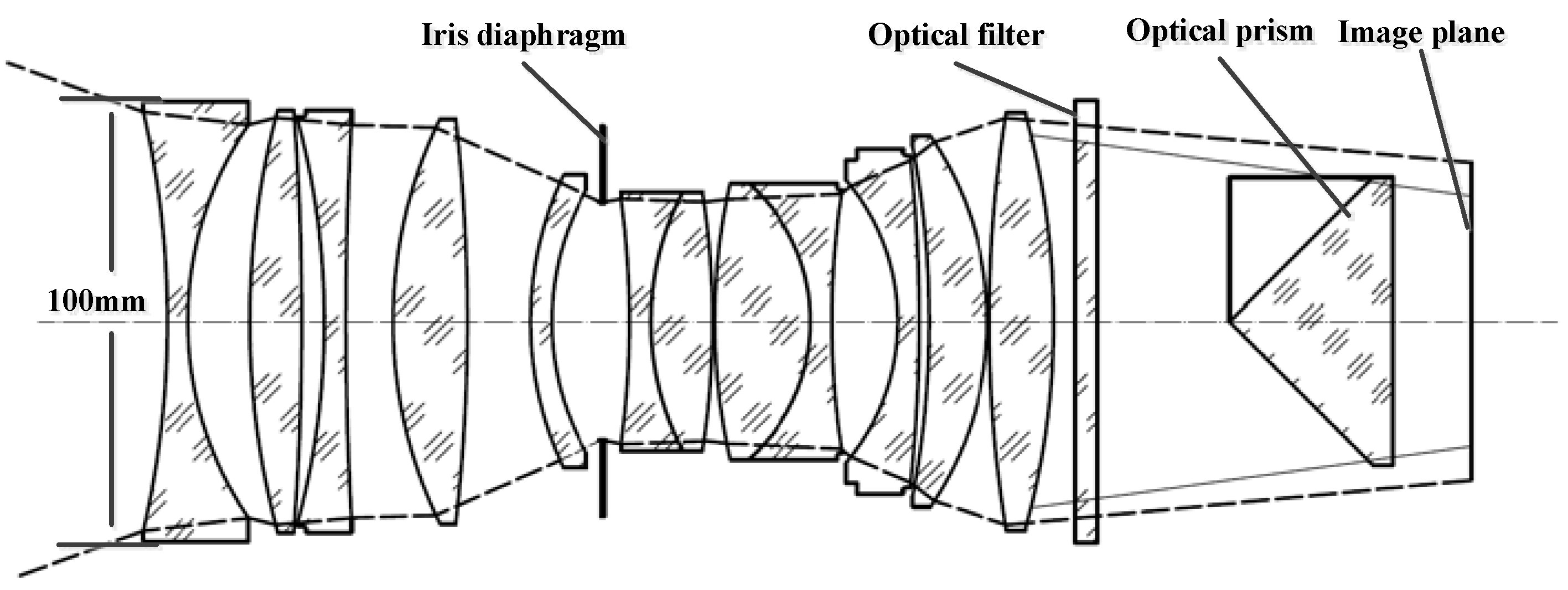
Based on the parameters of the optical system, the designed optical system is shown in Figure 2.

Figure 2.
Optical system diagram.
The optical system adopts an improved double Gaussian lens, and has a variable aperture to meet the imaging requirements of a wide dynamic range. To achieve the required imaging swath width, the detector scale needs to ensure at least 4 K × 4 K in image resolution. Optical stitching using four CMOS detectors is required for field of view expansion, and the optical system design should allow for sufficient back-working distance to accommodate the placement of a reflective prism assembly [14].
To minimize the impact of stray light on dynamic range, all optical components were coated with a high-transmission anti-reflective film using full dielectric materials. Within the spectral range of 0.4 μm to 0.7 μm, the reflectance of optical component surfaces was less than 0.5%. The optical lens structural elements underwent anti-stray light treatment (black oxidation + sandblasting + anti-glare threading + structural shaping), and a lens hood was added to the front end of the lens to further reduce stray light interference.
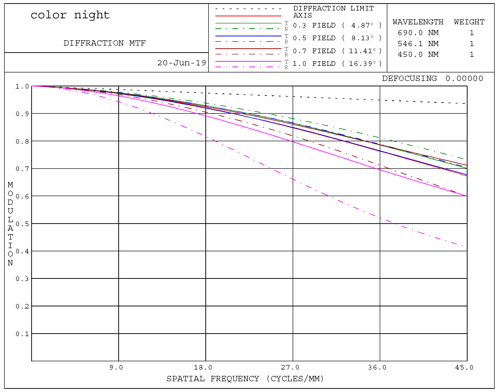
An analysis of the imaging quality of the optical system was conducted. Based on the CMOS pixel size, the modulation transfer function (MTF) of the optical system was calculated up to a spatial frequency of 45 lp/mm. Figure 3 shows the MTF curve of the system. It can be seen that when the optical system has an F-number of 2, the central field MTF is greater than 0.7 and the 0.7-field MTF is greater than 0.6, demonstrating the system’s good imaging performance.
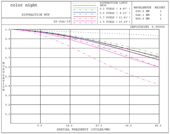
Figure 3.
MTF curve of the system.
2.4. Imaging Performance Estimation
2.4.1. Calculation of Swath Width
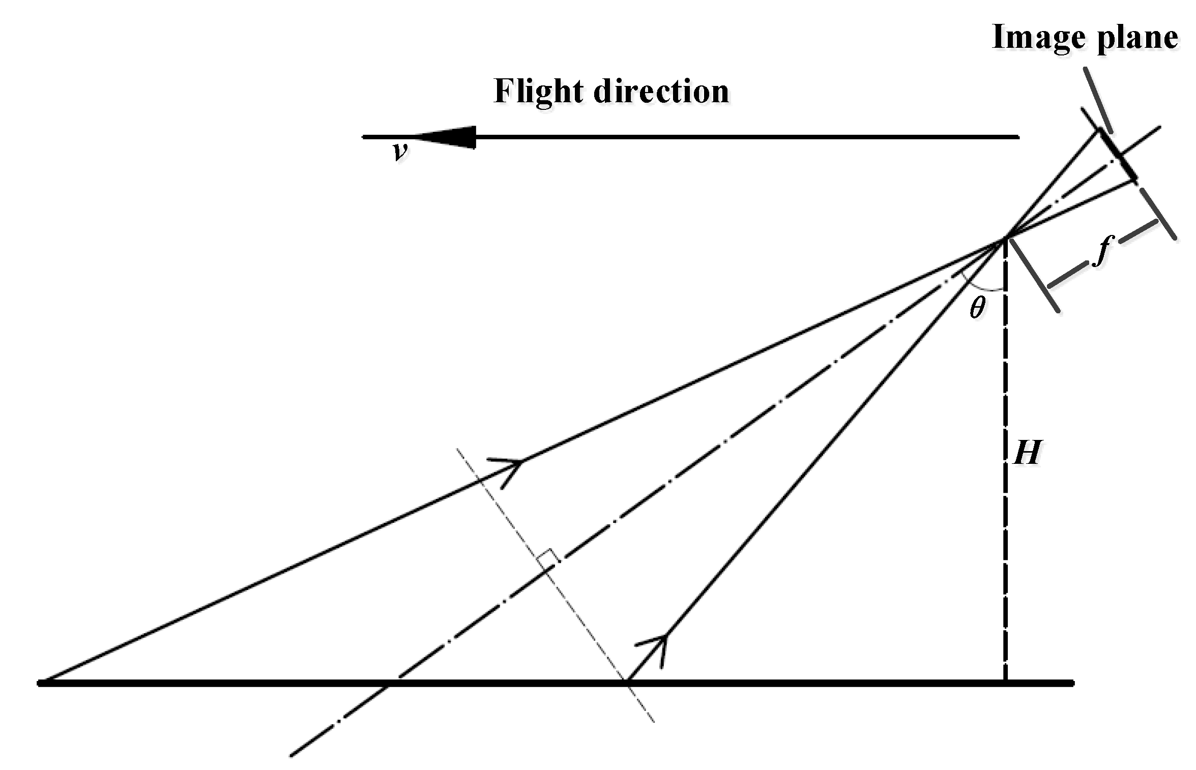
Based on the principles of geometric optics, the analytical model for the ground swath width of the imaging system is shown in Figure 4.
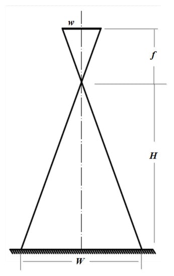
Figure 4.
The analytical model for the ground swath width.
The swath width can then be calculated as:
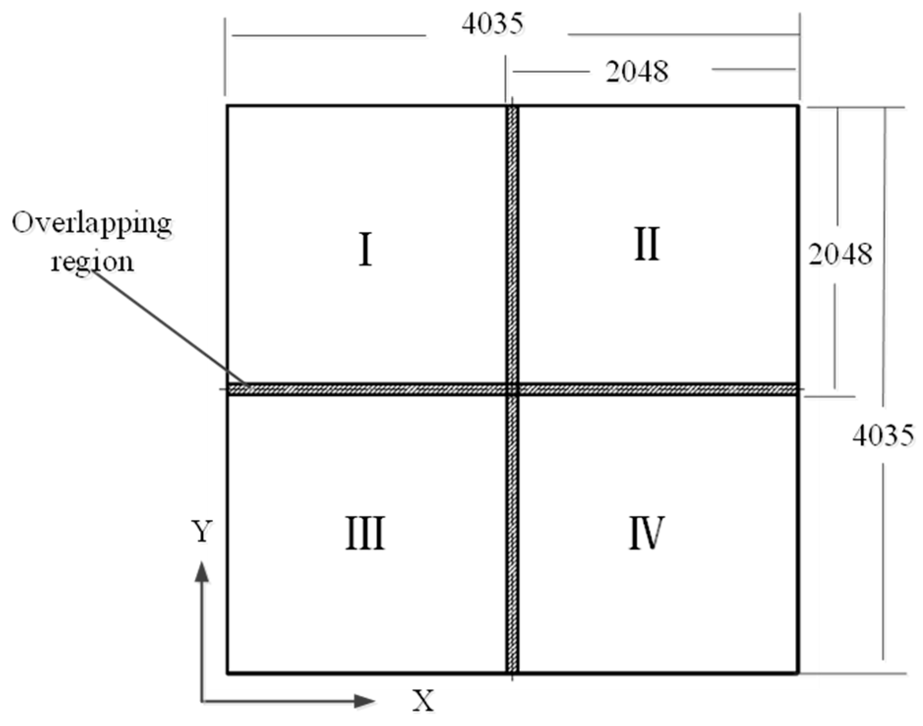
where H is the flight altitude, f is the focal length of the optical system, n is the number of pixels, and a is the pixel size. The selected CMOS detector resolution is 2048 × 2048, and the field of view is expanded by arranging four detectors in a 2 × 2 configuration, with a 3.0% overlap between adjacent detectors. After stitching, the resulting image resolution is 4035 × 4035. The calculated swath width of the low-light imaging system is W = 2.017 km (@5 km).
2.4.2. Exposure Time Estimation
The low-light imaging system is mounted on an airborne platform, and excessively long exposure times can cause forward image shift due to flight motion. The forward image shift mainly depends on the exposure time, imaging resolution, and speed–altitude ratio. A simplified analysis model is shown in Figure 5.
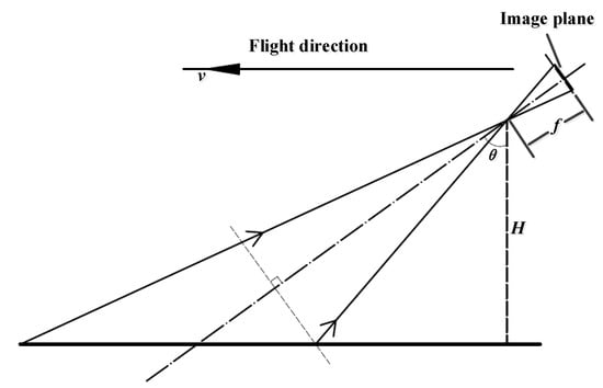
Figure 5.
Forward image shift analysis model.
To ensure clear imaging of the ground, the forward image shift should be less than half the pixel size. The exposure time can be expressed as:
where is the typical flight speed. For safety considerations, the nighttime flight speed is set to 200 km/h. The maximum exposure time for the low-light imaging system at typical flying altitudes is shown in Table 3.
Table 3.
Maximum exposure time of the system.
Therefore, in low illumination conditions during nighttime, the system can achieve a maximum exposure time of 4.5 ms for vertical downward viewing. By adopting a slant-forward view, the exposure time can be further increased to obtain better image quality.
2.4.3. Signal-to-Noise Ratio (SNR) Estimation
The SNR of the imaging system effectively reflects its detection sensitivity. The SNR is related to the imaging signal strength of the target and the detector’s intrinsic noise [15,16].
The imaging system’s SNR can be calculated by:
where Nsig represents the converted electron count of the light signal received by the detector and Nnoi is the detector’s noise electron count;
E is target illuminance (E = 0.01 lux);
ρ is target reflectance, considering a dark-colored tank (ρ = 0.3);
τa is atmospheric transmittance for mid-latitude regions on Earth at a flight altitude of 5 km and vertical downward viewing (τa = 0.7);
τo is the transmittance of the optical system (τo = 0.65);
tm is maximum exposure time (tm = 4.5 ms);
As is pixel area (As = 11 × 11 μm2);
F is the F-number of the optical system (F = 2).
The converted electron count from a single photon received by the detector can be simplified to:
According to the spectral response curve of the chip, the quantum efficiency in the wavelength range of 450 to 690 nm is with an average wavelength of .
The noise of the detector mainly includes readout noise, photon shot noise, dark current noise, and quantization noise. Readout noise and dark current noise can be directly obtained from the chip parameters. The standard deviation of photon shot noise is approximately equal to the square root of the signal electron count. The standard deviation of A/D quantization noise is related to the detector’s full well capacity and quantization bit number (12 bits), and is expressed as:
By Equation (3), the SNR of the imaging system is obtained, which is 18.9 dB. Under an illuminance of 0.01 lux, the system can meet the requirements of engineering applications when the SNR is greater than or equal to 15 dB. The calculation results indicate that the system has good adaptability to low-light environments.
3. RGB Filter Wheel Design
The reflected natural light from the target is filtered through the RGB color filters to obtain RGB single-channel images, which can be further fused to approximate a natural-looking color image. The R, G, and B color filters are installed on the filter wheel and rotated sequentially around its axis to switch between filters, thereby capturing the target’s RGB color images [17,18]. The selected wavelength bands and transmittance of each color filter are as follows:
R band: 620–680 nm, transmittance 96%, other wavelengths blocked.
G band: 500–540 nm, transmittance 96%, other wavelengths blocked.
B band: 440–480 nm, transmittance 96%, other wavelengths blocked.
The selection of these RGB filter wavelengths not only considers the requirements for low-light true-color imaging but also extends the application of low-light night vision in the field of low-light remote sensing for object discrimination [18].
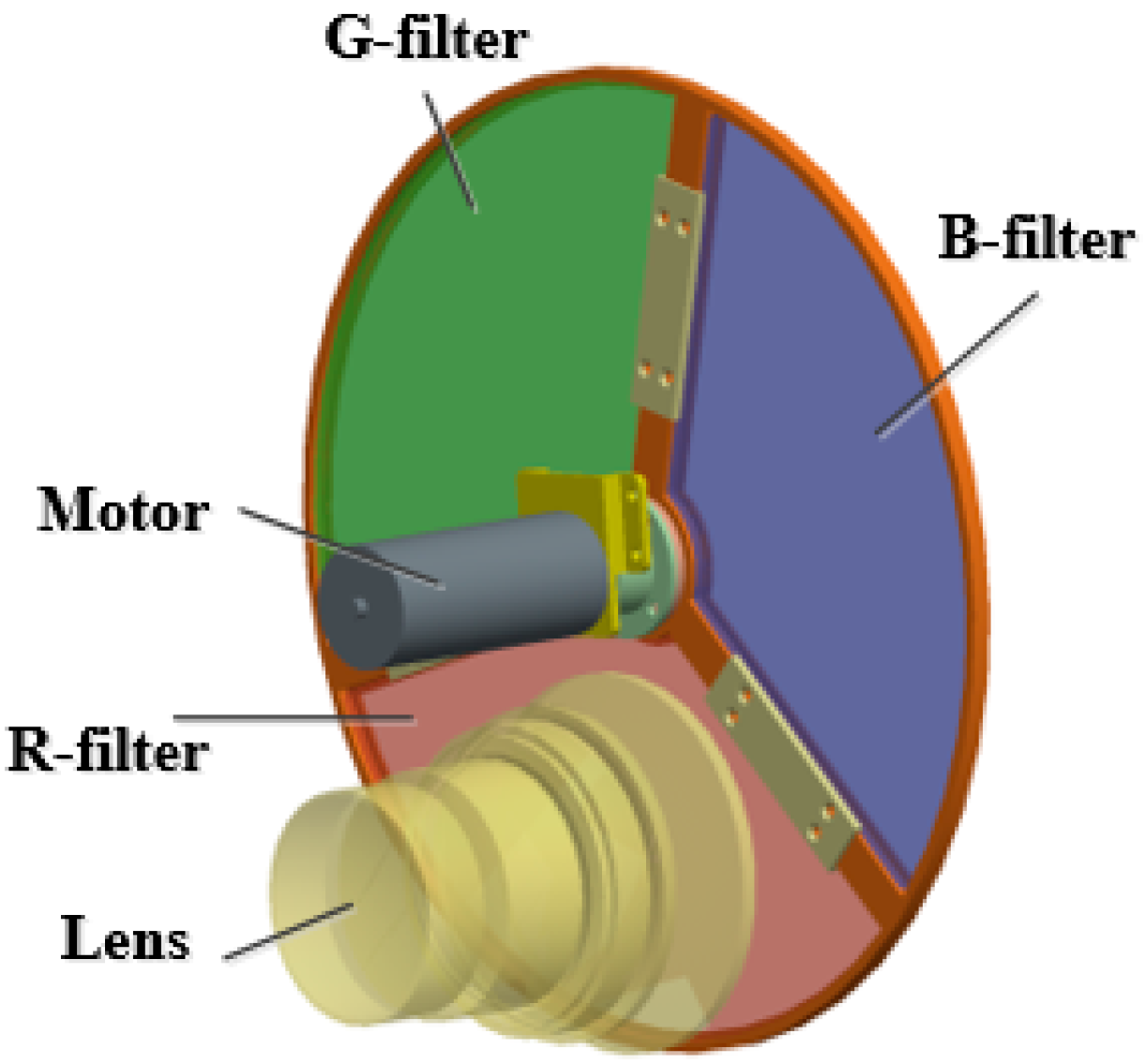
The RGB filter wheel mainly consists of a support bracket, three-color filters, bearings, drive motors, encoders, and Hall effect switches. Its three-dimensional model is shown in Figure 6. According to the requirements of the imaging system’s spectral channels, the filter wheel contains three filters and is located between the optical objective group and the imaging components. The bearings are preloaded and the shaft holes are matched during assembly to restrict radial movement of the filter wheel, ensuring that the rotational tilt angle of the filter wheel meets the requirements.

Figure 6.
RGB filter wheel model.
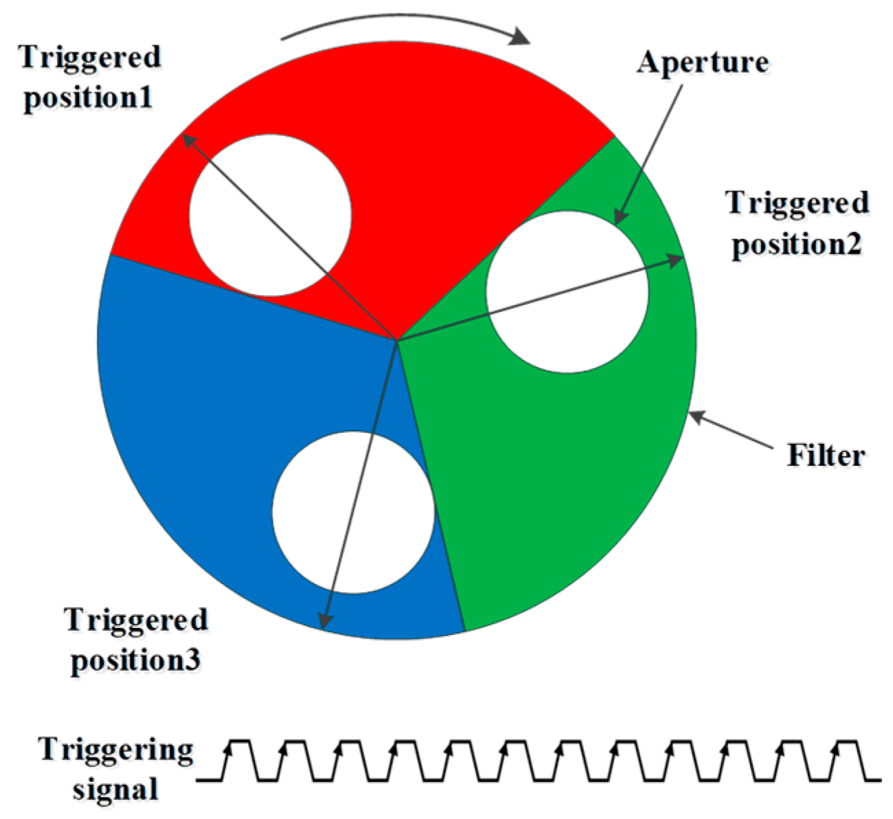
Each of the three filters on the filter wheel’s starting positions is equipped with a Hall effect switch. When a filter reaches the aperture position, it triggers the exposure and provides synchronous exposure signals to the image sensor. The operational mode is illustrated in Figure 7.
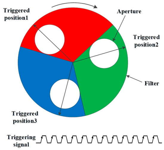
Figure 7.
Synchronous triggering of the filter wheel.
For every rotation of the filter wheel, the detector undergoes three exposures, obtaining RGB color images that are merged into a single frame. The maximum frame rate of the detector is 25 frames per second, and the output frame rate of the color image is 8 frames per second. Therefore, the rotation speed (n) of the filter wheel is calculated as:
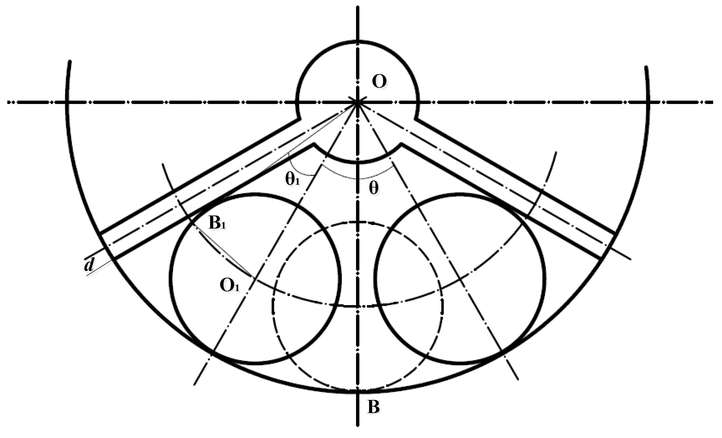
During the rotation of the filter wheel, to ensure that the exposure time within each individual color filter segment meets the requirements, the time when the aperture is located within a specific color filter should be greater than the exposure time, and the maximum diameter of the filter should cover the aperture. The calculation model is shown in Figure 8.

Figure 8.
Synchronous triggering of the filter wheel.
Based on the previous analysis, with a maximum exposure time of 22.5 ms for the detector, the angle (θ) through which the filter wheel rotates during the exposure time is:
The maximum radius OB of the filter wheel is given by:
where θ1 is the distance between the optical axis and the rotational center of the filter wheel and d is the maximum radius of the aperture, which is limited by the exit pupil diameter of the optical system.
According to geometric relationships, the arc length swept by the aperture within the exposure time must be smaller than the arc length of a 120° arc with a radius of OO1, i.e.:
where θ1 is the angular aperture of the aperture with respect to the rotational center and d is the half-width of the filter wheel bracket. θ1 can be determined from the following equation:
By solving Equations (5)–(7) simultaneously, the maximum size of the filter can be obtained.
4. Optical Stitching of the Reflective Prism
A large format is crucial for the low-light imaging system to ensure a wide swath width and high resolution. Four reflective prisms are arranged in a configuration similar to four small squares, forming a larger square. This arrangement divides the imaging beam into four parts, which are then captured by four COMS detectors. The four detectors are positioned around the reflective prisms, as shown in the schematic diagram of the equivalent image plane in Figure 9.
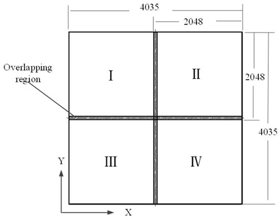
Figure 9.
Equivalent image plane of the system.
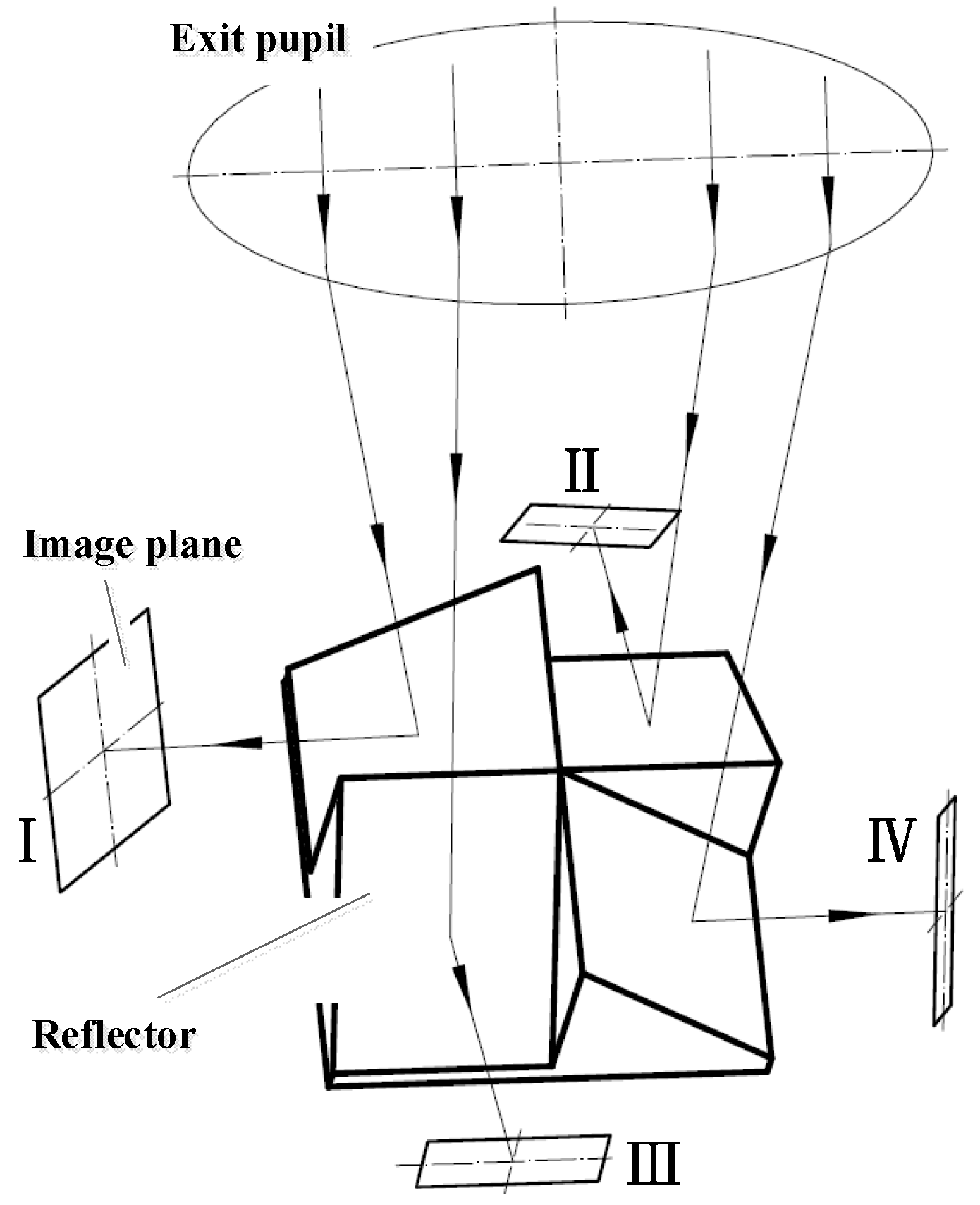
The direct stitching of the detector chips is challenging, and it is almost impossible to achieve seamless integration. Therefore, the four detectors need to be dispersed in three-dimensional space to effectively utilize the image plane. A four-panel reflective prism is employed to implement the strategy of dividing the light paths into four channels. The reflective surfaces of the prisms are inclined at 45° to the optical axis. The four light paths pass through the reflective prism assembly and project onto four groups of high-sensitivity detector components in four directions in three-dimensional space [19,20,21]. The working principle of the reflective prism assembly is illustrated in Figure 10.
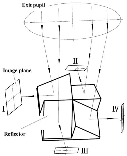
Figure 10.
Working principle of the reflective prism assembly.
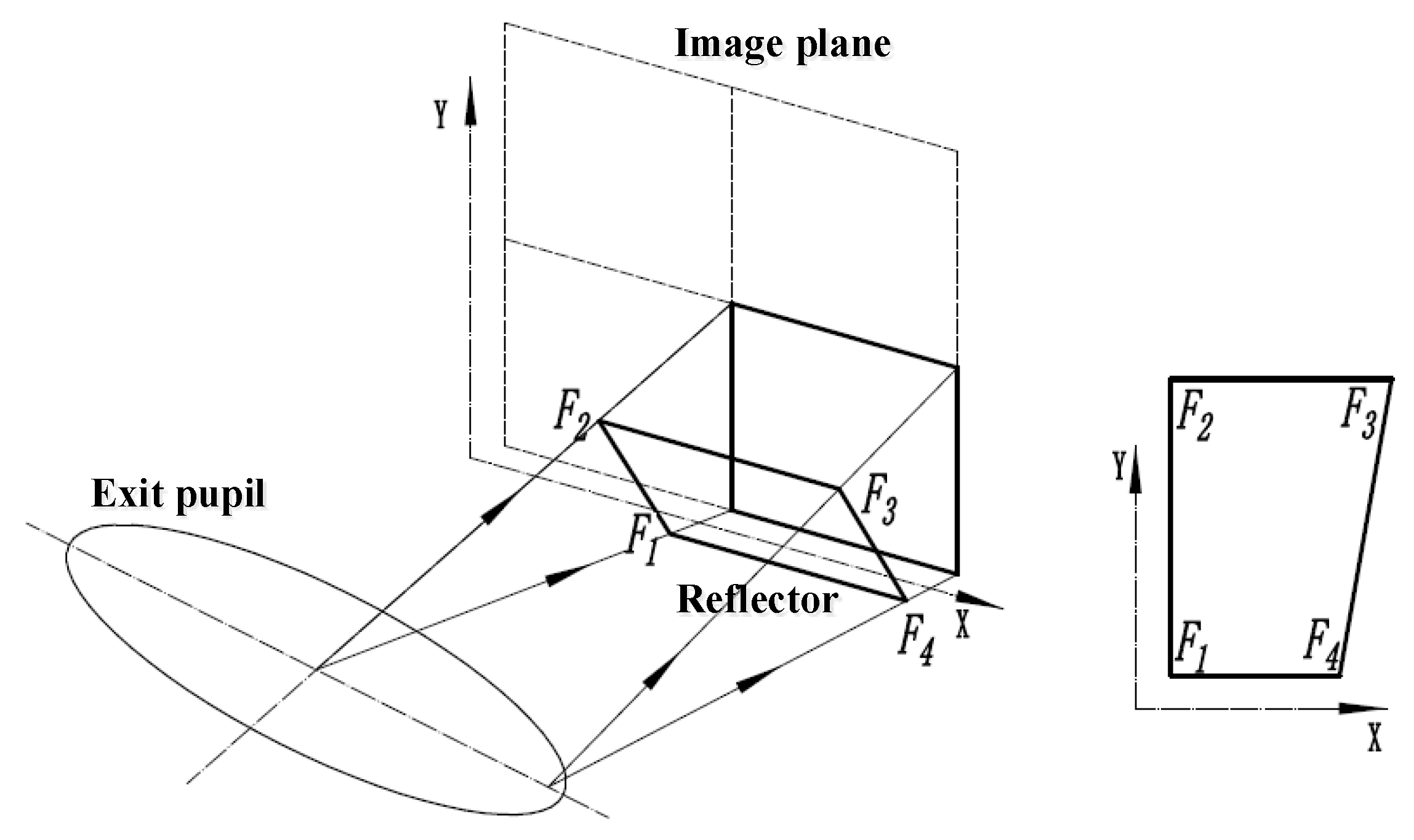
The size and height of the reflective prism vary with its position in the optical path. The relationship between the prism size and the optical path is depicted in Figure 11. The length of the 45° reflective prism is greater near the exit pupil position than the farthest position, forming a trapezoidal effective reflective surface [22,23].

Figure 11.
Relationship between reflective prism and focal plane size.
A calculation model is established to determine the relationship between the edge rays of the field of view and the size of the reflective prism, as shown in Figure 12.
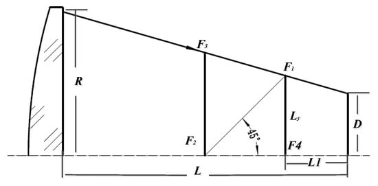
Figure 12.
Relationship between reflective prism size and edge rays.
Here, R is the optical exit pupil radius, D is the size of a single detector, L is the back-working distance of the optics, and L1 is the distance between the placement of the reflective prism and the detector. Based on geometric relationships, the length of the reflective prism in the Y direction is given by:
The Y dimension of the reflective prism determines the relative positions of the two edges F1F4 and F2F3, and their different positions will result in different widths in the X direction. According to geometric relationships, the lengths of the reflective prism in the X direction are:
For ease of engineering implementation, the projected surfaces of the reflective prism along the optical axis direction are designed as rectangles, with dimensions that cover the theoretically calculated maximum size. Moreover, the design of the reflective prism incorporates a 3% overlap between the stitched fields of view.
5. Mechanical Configuration of the System
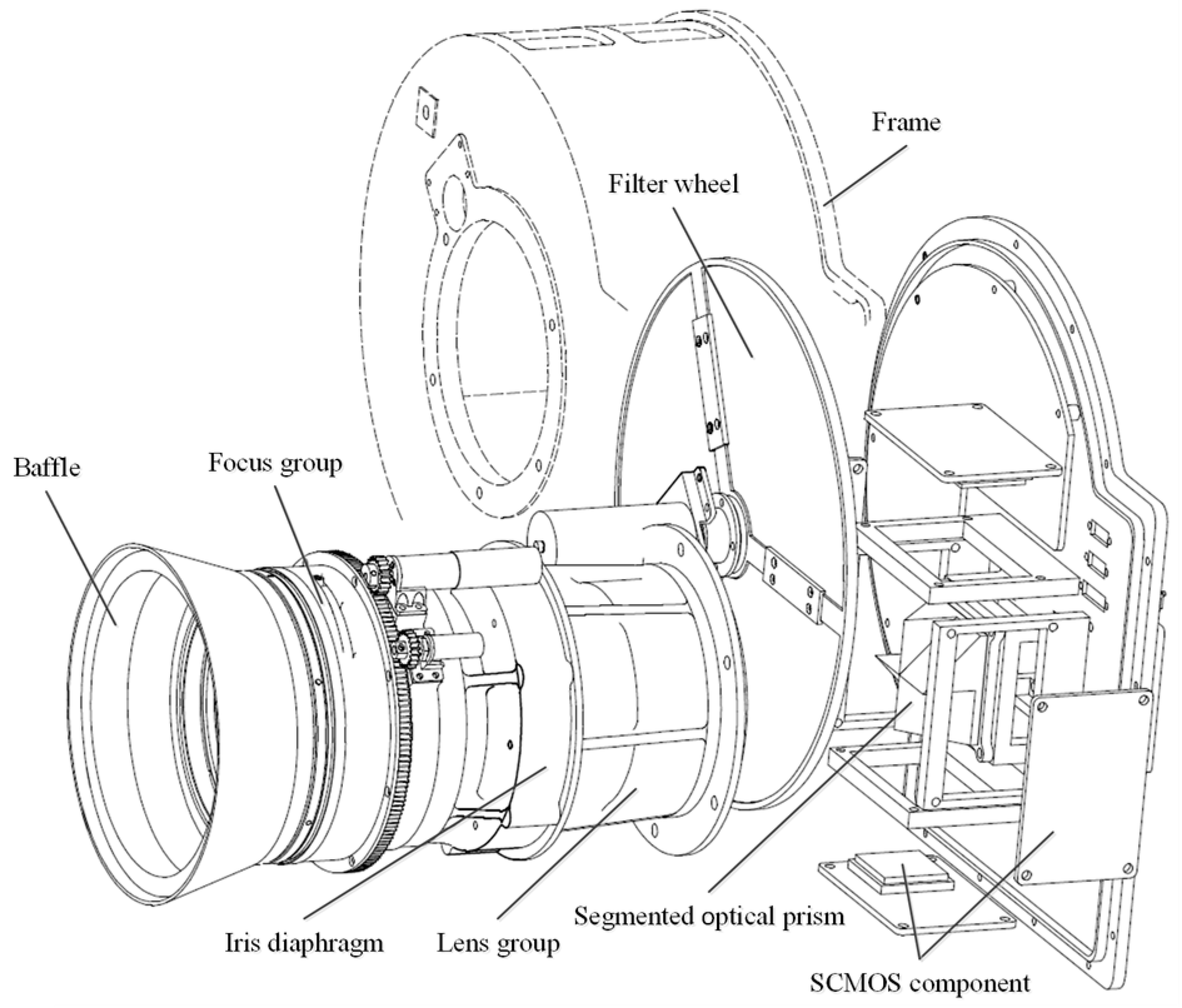
Based on research on the working principles of the system, the overall mechanical configuration of the low-light imaging system was completed. The system is divided into three main components: the optical lens, the filter wheel assembly, and the imaging component composed of multiple stitched sensors. The system diagram is shown in Figure 13. The optical lens includes a lens hood, a variable aperture, and a focusing lens group. The variable-aperture component allows continuous adjustment of the lens aperture from F/2 to F/20, with a maximum aperture diameter of 100 mm. The focusing lens group, driven by a cam mechanism, has a focusing range of ±2 mm to compensate for defocusing caused by changes in working distance. The filter wheel has a diameter of 250 mm, and the filter segments are shaped like 120° sectors. The optical reflective prism group is bonded inside the prism holder and placed at the rear of the optical lens. The four detectors are distributed around the support structure. Both the filter wheel and the imaging component are integrated within a sealed enclosure to eliminate external stray light interference.
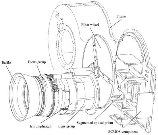
Figure 13.
Explosive view of the system.
6. Experimental Verification and Results
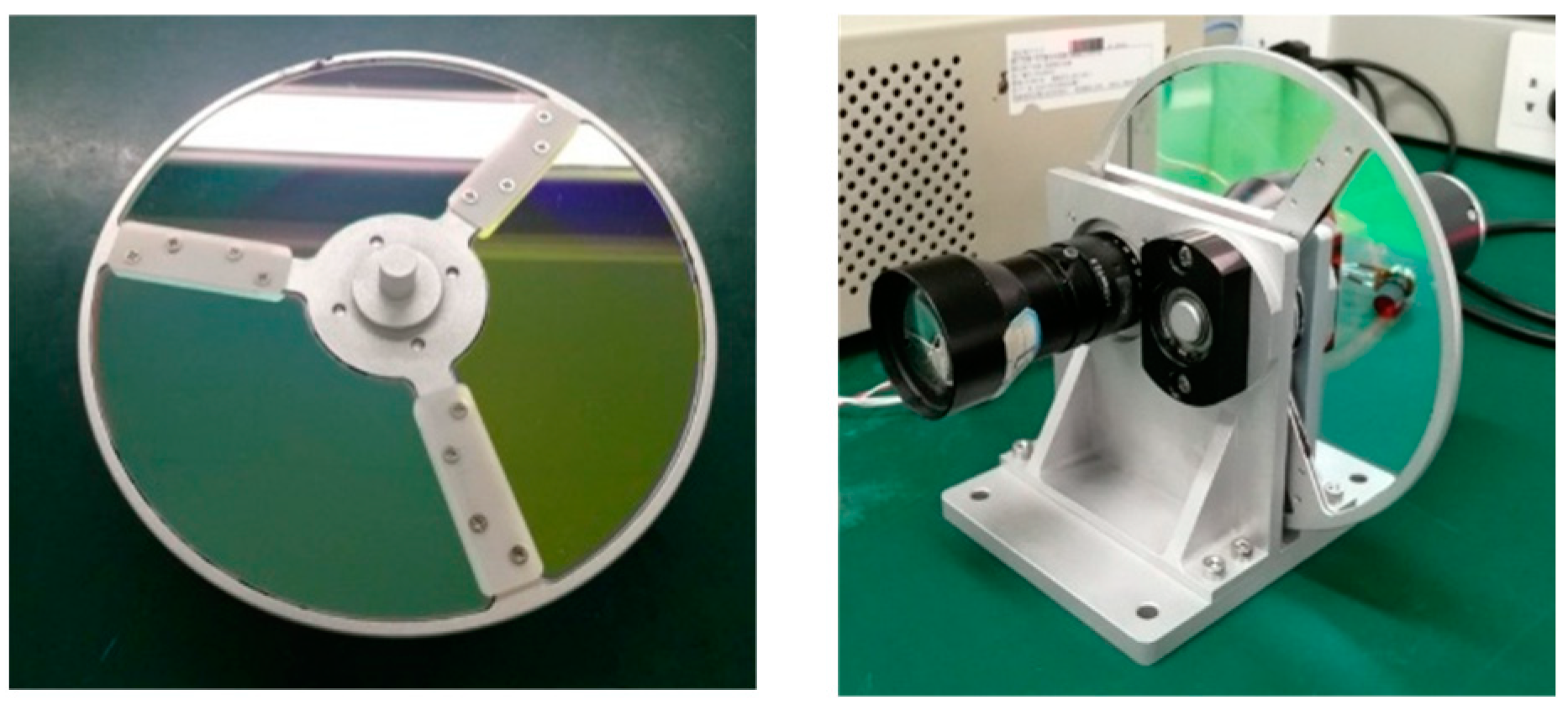
To verify the effectiveness of the RGB filter wheel in fusing low-light images into true-color images, experiments were conducted using a large-aperture short-focus lens matched with a single high-sensitivity detector. The filter wheel and the experimental prototype are shown in Figure 14.

Figure 14.
Stitched reflective prism assembly.
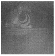
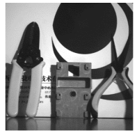
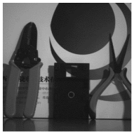
The experiments were conducted in a darkroom with adjustable environmental illumination ranging from 0.01 to 10,000 lux, and the targets captured were in color. The acquired monochrome images and the fused true-color images are shown in Table 4. It can be observed that even in low-light conditions of 0.01 lux, the RGB channel images obtained using the filter wheel still maintain high resolution and contrast. In higher illuminations, the images are clear with sharp details. After image fusion, the color information of the targets can be restored, resulting in clear, high-resolution, and richly saturated true-color images. This demonstrates that the low-light imaging system based on the RGB filter wheel has excellent low-light imaging capabilities and a high dynamic range.
Table 4.
RGB images and fusion results.
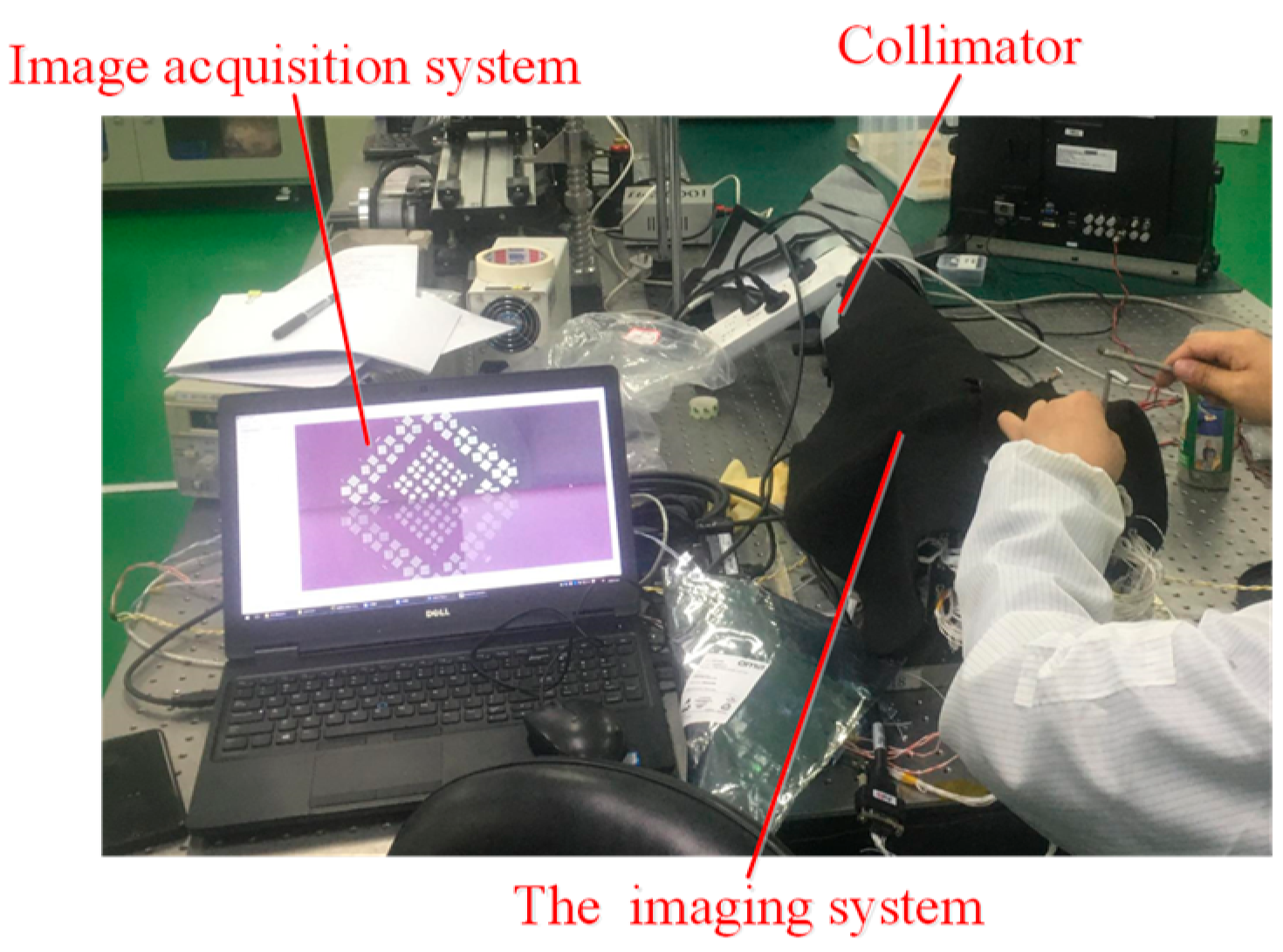
Based on the research and design results mentioned above, the entire system was manufactured and assembled. The field stitching was adjusted using parallel light pipes and gradient rate targets. The adjustment was carried out at the site shown in Figure 15. The overlap ratio was controlled within 3% for each stitched field. Image stitching software was used to ensure a stitching accuracy of within three pixels between adjacent fields.

Figure 15.
Site of field stitching and adjustment.
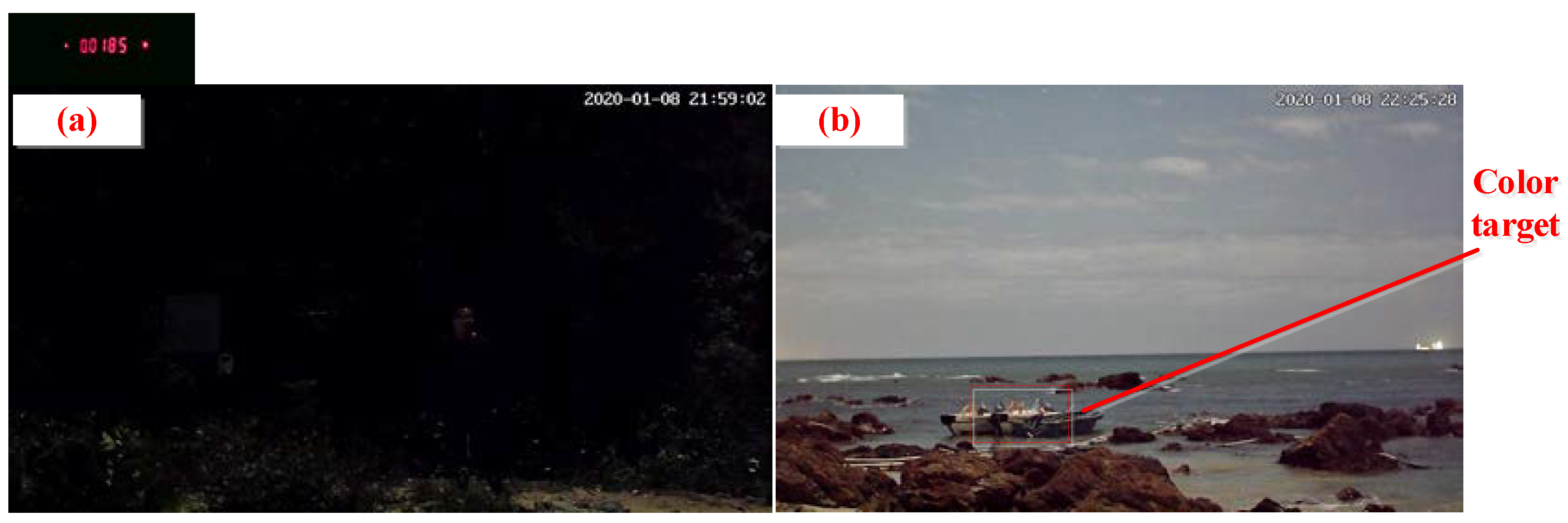
Furthermore, field experiments were conducted to evaluate the imaging capabilities of the low-light imaging system. The experiments were conducted in overcast and moonless conditions in a coastal beach to avoid artificial light interference from urban areas. The ground illuminance was measured to be 0.01 lux, using a high-precision illuminometer. A comparison was made between images acquired by a conventional camera and the low-light imaging system, as shown in Figure 16.
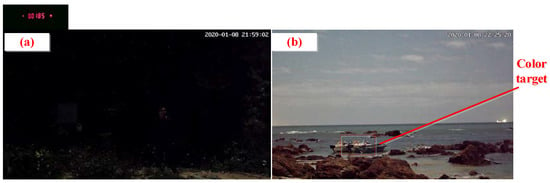
Figure 16.
(a) Image captured by conventional camera; (b) image captured by the low-light imaging system.
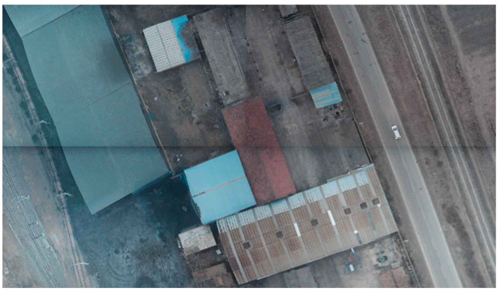
To further validate the performance of the integrated large-format low-light imaging system, aerial dynamic tests were conducted in December 2021 at 5:30 a.m. at Neifu Airport in Shaanxi Province, China, with ground illuminance ranging from 1 to 10 lux. Figure 17 shows a single frame image captured during the aerial tests. The results demonstrate that the low-light imaging system can produce high-contrast and high-definition images in low-light airborne environments, while providing RGB true-color image output. The fields in the aerial images are stitched with high accuracy. Each single image has a large coverage area and clear visibility of buildings, farmland, and trees, resulting in sharp edges. The calculated ground resolution reached 0.2 m per pixel at an altitude of 2 km, indicating the system’s excellent long-range and large-format imaging capabilities. The flight tests also verified the stability and reliability of the airborne imaging capabilities of the system.

Figure 17.
A single frame image captured during the aerial tests.
7. Conclusions
This study designed, developed, and tested a large-format low-light true-color imaging system for airborne platforms. To capture color information under extremely low-light conditions, a technique utilizing an RGB filter wheel, high-sensitivity COMS detectors, and multi-line sequential exposure was proposed to achieve the fusion of true-color low-light images. An SNR calculation model for the low-light imaging system was established, and its low-light imaging capabilities were thoroughly evaluated. The relationship between the filter wheel’s rotation speed, sector size, and exposure strategy was determined, and the filter wheel parameters were calculated. The calculation method for the structural parameters of the four-panel reflective prism was studied, and mathematical expressions for the geometric parameters of the prism were provided. Based on these research results, the design of the large-format low-light imaging system based on the RGB filter wheel was realized. Laboratory and field experiments confirmed that the system can produce high-contrast true-color images in low-light conditions of 0.01 lux, and all performance indicators of the system meet the design requirements. The research findings and design methodology presented in this study have reference value for the design of airborne low-light imaging equipment.
Author Contributions
Conceptualization, J.P.; methodology, J.P. and Y.M.; software, J.P. and X.S.; writing—original draft preparation, J.P.; writing—review and editing, H.Y. and W.C.; supervision, G.Z. All authors have read and agreed to the published version of the manuscript.
Funding
This research received no external funding.
Institutional Review Board Statement
Not applicable.
Informed Consent Statement
Not applicable.
Data Availability Statement
The data presented in this study are available from the first author or the corresponding author upon reasonable request.
Acknowledgments
I would like to thank my friends and family who gave me much encouragement and financial support respectively. And I wish to extend my thanks to the library and the electronic reading room for their providing much useful information for my thesis.
Conflicts of Interest
The authors declare no conflict of interest.
References
- Ke-Cong, A.I. Development and prospect of low-light-level(LLL) night vision technology. J. Appl. Opt. 2006, 27, 303–307. [Google Scholar]
- Tian, J.S. New Development of Low Light Level Imaging Sensor Technology. Infrared Technol. 2013, 39, 527–537. [Google Scholar]
- Jin, W.Q.; Wang, L.X.; Zhao, Y.M.; Shi, S.M.; Wang, X. Developments of image processing algorithms for color night vision. Infrared Laser Eng. 2008, 37, 147–150. [Google Scholar]
- Wu, H.; Tao, S.; Zhang, L.; Zhang, J. Tricolor acquisition and true color images fusion method under low illumination condition. J. Appl. Opt. 2016, 37, 673–679. [Google Scholar]
- Tang, H.; Zhu, H.; Fei, L.; Wang, T.; Cao, Y.; Xie, C. Low-Illumination Image Enhancement Based on Deep Learning Techniques: A Brief Review. Photonics 2023, 10, 198. [Google Scholar] [CrossRef]
- Qian, X.; Wang, Y.; Wang, B. Effective contrast enhancement method for color night vision. Infrared Phys. Technol. 2012, 55, 130–136. [Google Scholar] [CrossRef]
- Qian, X.; Han, L.; Wang, Y.; Wang, B. Color contrast enhancement for color night vision based on color mapping. Infrared Phys. Technol. 2013, 57, 36–41. [Google Scholar] [CrossRef]
- Qadir, H.A. Enhancing thermal video using a public database of images. In Multisensor, Multisource Information Fusion: Architectures, Algorithms, and Applications 2014; SPIE: Bellingham, WC, USA, 2014. [Google Scholar]
- Jorden, P.R.; Morris, D.G.; Pool, P.J. Technology of large focal planes of CCDs. In Proceedings of the SPIE—The International Society for Optical Engineering, Denver, CO, USA, 2 August 2004; Volume 5167, pp. 72–82. [Google Scholar]
- Shi, L. Research on a Mechanical Interleaving Stitching Method of CCDs for Remote Sensing Camera. Infrared 2009, 30, 12–15. [Google Scholar]
- Rogalski, A. Progress in focal plane array technologies. Prog. Quantum Electron. 2012, 36, 342–473. [Google Scholar] [CrossRef]
- LI, Z.; Wang, Z.; Wu, K. Optical assembly of CCD focal plane for space camera. Opt. Precis. Eng. 2000, 8, 213–216. [Google Scholar]
- Li, F.; Zhang, X.; Cai, W.; Chang, J.; Gao, L. Parameter Calculation of Splitting Mirrors in Optical-Butting Focal Plane. Acta Opt. Sin. 2020, 40, 1308001. [Google Scholar]
- Guo, J.; Gong, D.; Zhu, L.; Sun, J.; Shao, M. Calculation of overlapping pixels in interleaving assembly of CCD focal plane of mapping camera. Opt. Precis. Eng. 2013, 21, 1251–1257. [Google Scholar]
- Liu, Q.; Liu, L.; Deng, Y.; Song, J. Apparent distance theory revision for low-light-level night vision system based on noise factor. Opt. Quantum Electron. 2017, 49, 249. [Google Scholar] [CrossRef]
- Lu, C.; Liu, C.; Shao, M.; Wu, Z.; Jiang, C.; Cao, J.; Chen, T. Design and Performance Analysis of the Highly Sensitive Deep Vacuum Cooling sCMOS Imaging System for Highly Sensitive Detection of Space Targets. Photonics 2023, 10, 819. [Google Scholar] [CrossRef]
- Tang, X.; Yao, L. Design of optical filters for three primary colors. Laser Technol. 2014, 38, 274–277. [Google Scholar]
- Sun, Y.; Lou, C.; Jiang, Z.; Zhou, H. Experimental research of representative wavelengths of tricolor for color CCD camera. J. Huazhong Univ. Sci. Technol. 2009, 37, 108–111. [Google Scholar]
- Marks, D.L. Close-up imaging using microcamera arrays for focal plane synthesis. Opt. Eng. 2011, 50, 33205. [Google Scholar] [CrossRef]
- Lu, H.Y.; Liu, Y.; Guo, Y.F. Computation of overlapping pixels of mechanical assembly CCD focal planes in remote sensing cameras. Opt. Eng. 2012, 20, 1041–1047. [Google Scholar]
- Jia, X.Z.; Jin, G. Design and Precision measurement of TDICCD Focal Plane for Space Camera. In Proceedings of the 6th International Symposium on Advanced Optical Manufacturing and Testing Technologies: Optoelectronic Materials and Devices for Sensing, Imaging, and Solar Energy, Xiamen, China, 15 October 2012. [Google Scholar]
- Chen, X.; Lv, Q. Microbolometric theoretical output responsivity analysis for focal plane array. Opt. Eng. 2015, 54, 63105. [Google Scholar] [CrossRef]
- Ge, M.; Xu, Y.; Shen, H.; Liu, W. Multiple degrees of freedom mechanical interleaving stitching method of CCDs for aero-camera. Infrared Laser Eng. 2015, 44, 923–928. [Google Scholar]


Disclaimer/Publisher’s Note: The statements, opinions and data contained in all publications are solely those of the individual author(s) and contributor(s) and not of MDPI and/or the editor(s). MDPI and/or the editor(s) disclaim responsibility for any injury to people or property resulting from any ideas, methods, instructions or products referred to in the content. |
© 2023 by the authors. Licensee MDPI, Basel, Switzerland. This article is an open access article distributed under the terms and conditions of the Creative Commons Attribution (CC BY) license (https://creativecommons.org/licenses/by/4.0/).