Kramers–Kronig Transmission with a Crosstalk-Dependent Step Multiple-Input Multiple-Output Volterra Equalizer in a Seven-Core Fiber

 , , , , , , and
Abstract
:1. Introduction
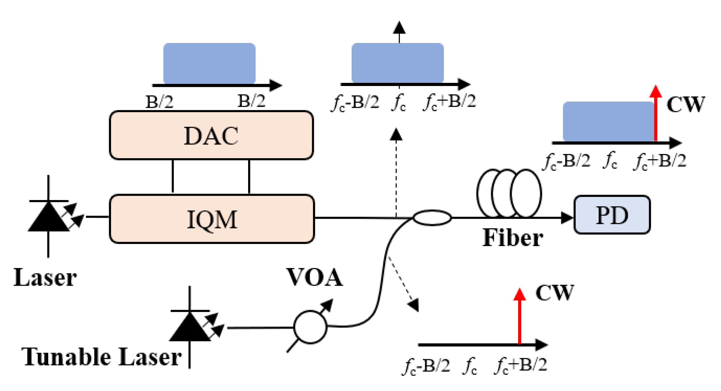
2. Principle of KK Transmission System
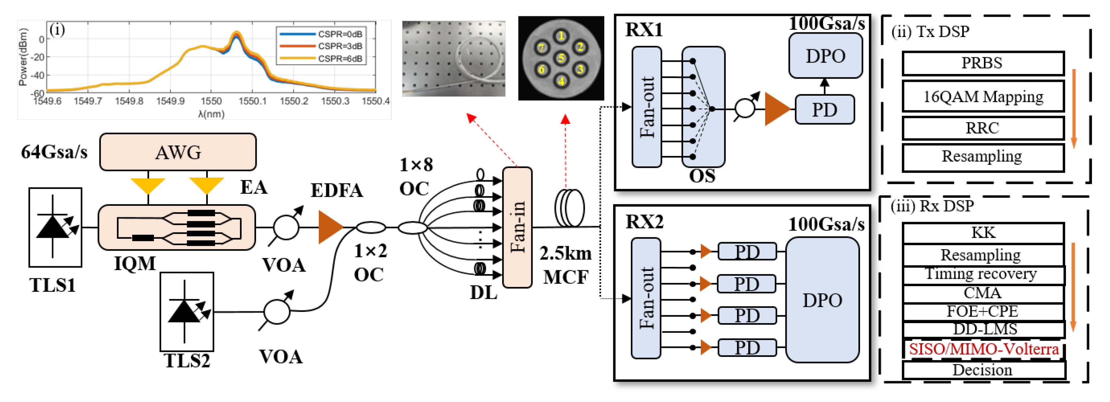
3. Experimental Setup and Analysis of Seven-Core Transmission System with KK Receiver
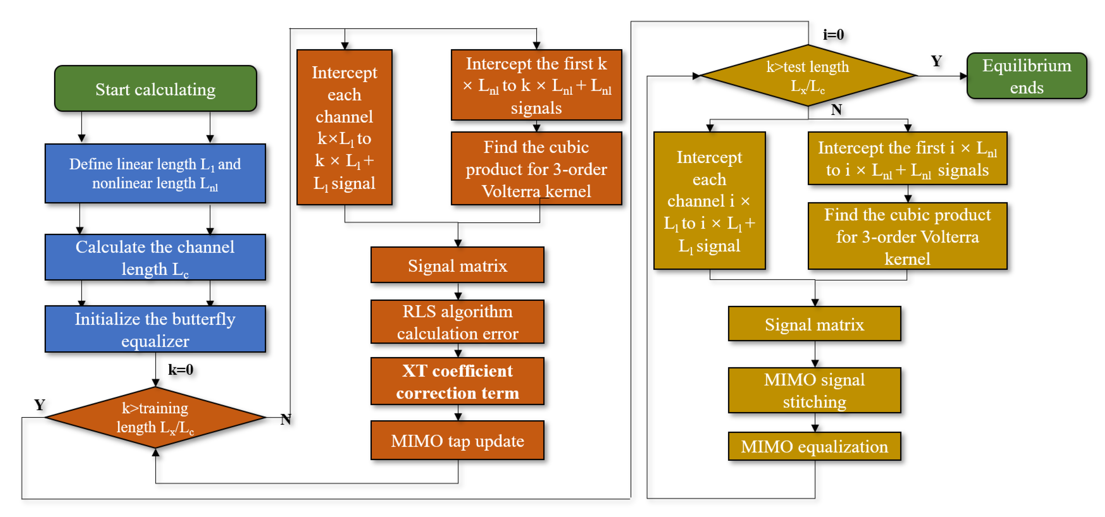
4. XT-MIMO Nonlinear Equalization Algorithm Based on Volterra Series
- Assume that the 16-QAM signal data matrix for all cores input to the equalizer is represented aswhere represents signal and each channel includes the training signal and the payload signal.
- Calculate the third-order nonlinear length as
- Calculate the total channel length as
- Initialize the butterfly equalizer, and the tap coefficient of the equalizer can be expressed asLet is 1, where and the other terms of are 0. is a column vector of length .
- Intercept the to signals of each core from and arrange them in reverse order to obtain the linear input sequence of the equalizer for each channel asIntercept the signals from to of each core and arrange them in reverse order, using (12) to find the cubic product of the input signals corresponding to the third-order Volterra kernel for each channel.where
- Splice the linear sequence with a third order to obtain the input sequence for each channel, shown as
- Splice the MIMO equalizer input sequence of each channel into a MIMO input sequence, as shown in (14).
- Calculate the MIMO output signal as
- Calculate the error aswhere is the corresponding original signal.
- Update the inverse of the correlation matrix as [34]:where is the inverse of the correlation matrix, and is initialized to a unit matrix. is called the forgetting factor, which has some forgetting effect on historical data. In this paper, , which means no forgetting effect.
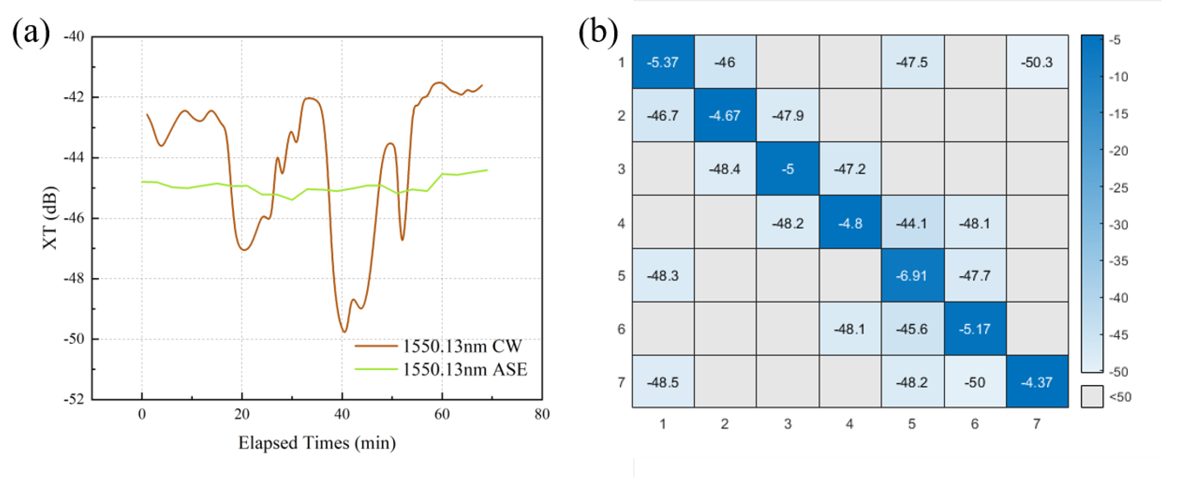
- Calculate the crosstalk coefficient matrix according to the measured crosstalk matrix aswhererepresents the value of the measured crosstalk level of k-th time interval, and are the maximum and minimum values in the crosstalk matrix, respectively. is the scaling factor. For example, in Figure 3b, , and , which is negligible for less than −50 dB (gray cells in the crosstalk matrix), corresponding to of 0. Since the inter-core XT changes relatively slowly, the crosstalk matrix is collected once in one minute. We use the average crosstalk power in one minute for the calculation of the algorithm crosstalk coefficient, i.e., . The transmitted signal is processed with the crosstalk matrix in the corresponding time interval. Considering that is a singular matrix, the inverse matrix of is
- See Appendix A for a detailed explanation of the derivation process.
- Repeat steps 5 to steps 12 until the end of the training signal is updated and converged.
- Extract the payload signal and repeat steps 5 to steps 8 until the end of the payload signal is updated, and complete the MIMO equalization.
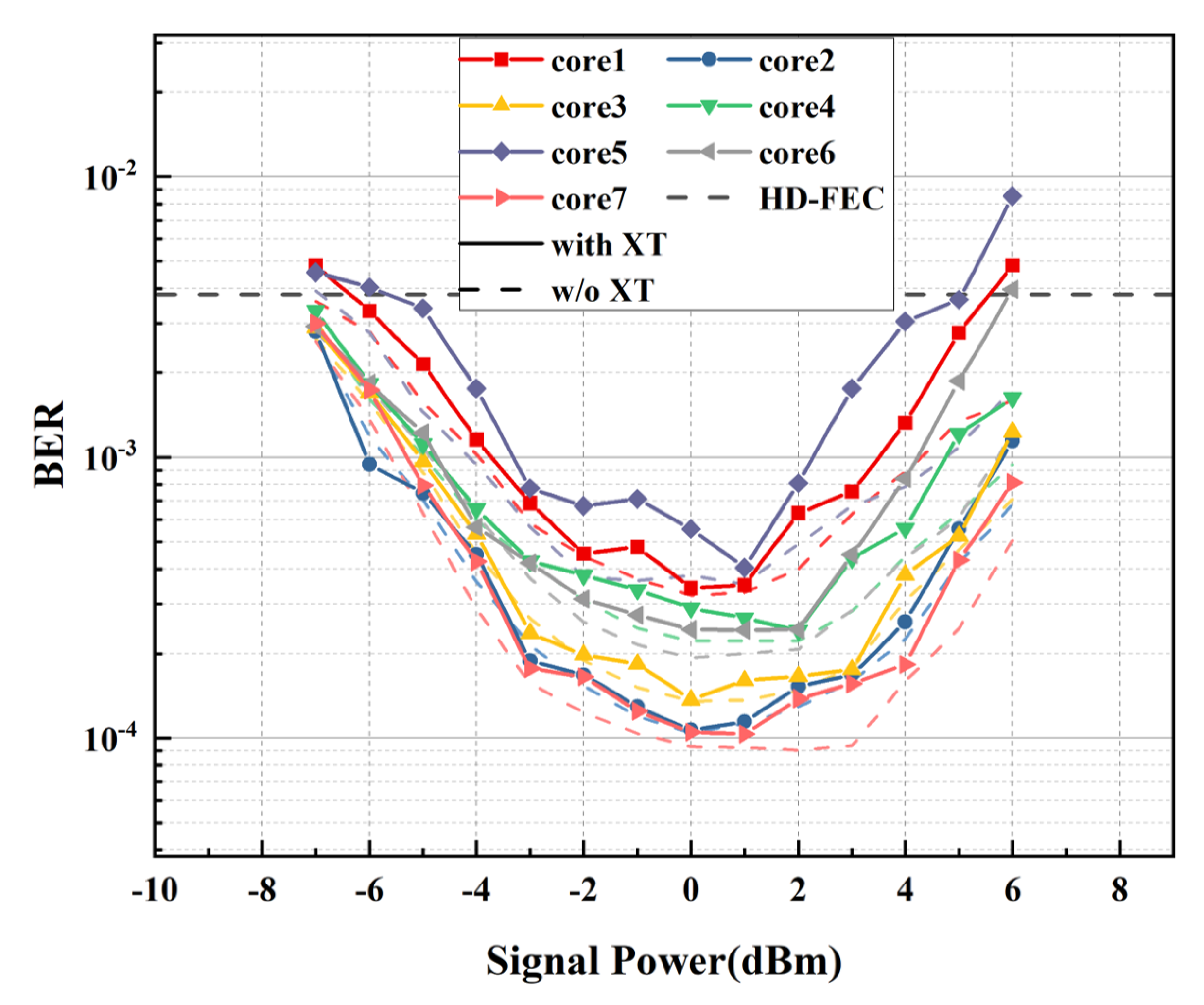
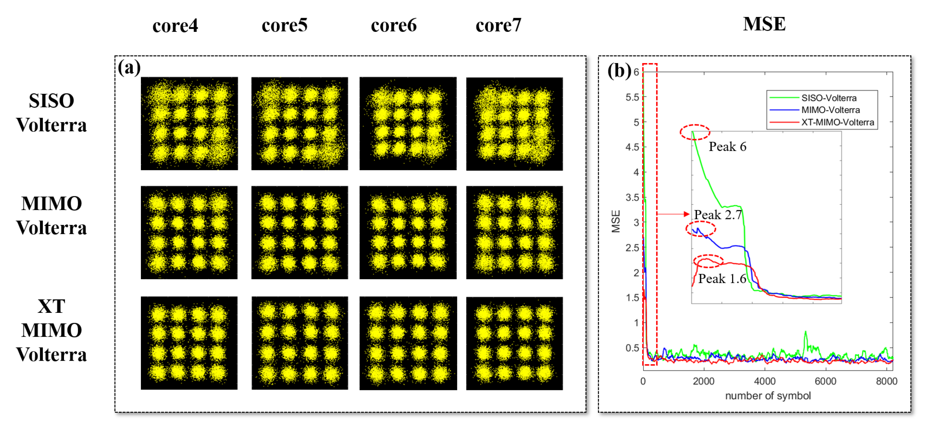
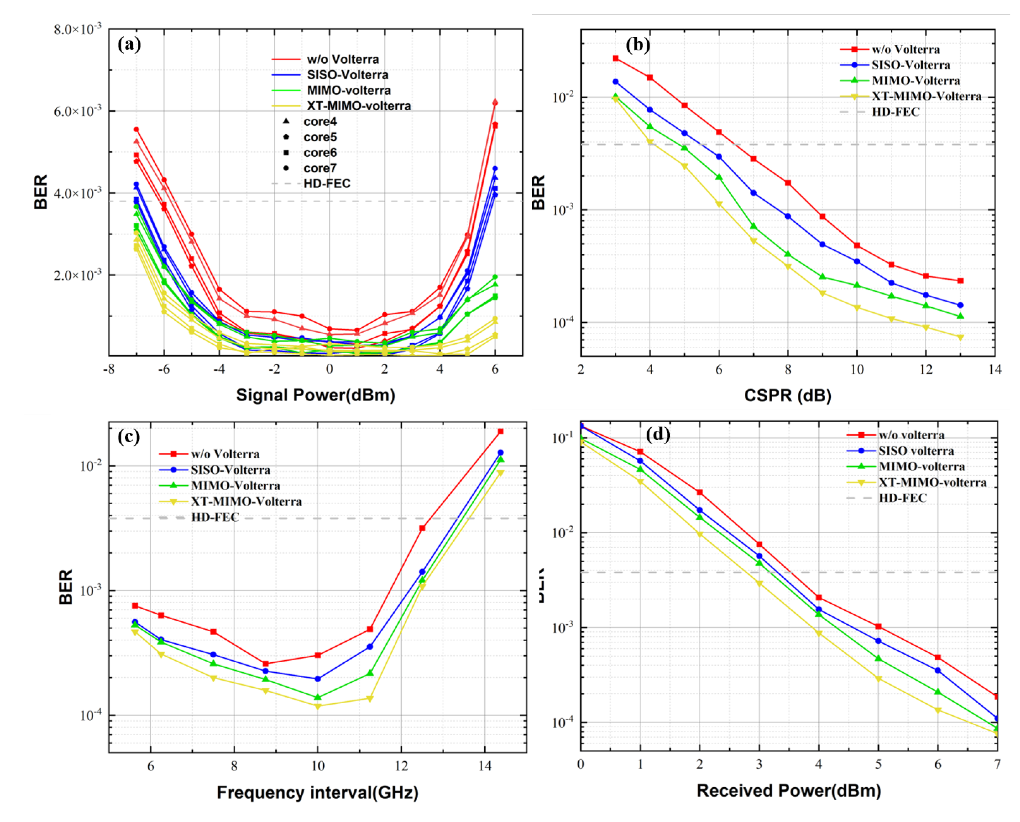
5. Experimental Results and Performance Analysis of XT-MIMO Nonlinear Equalization
6. Conclusions and Discussion
Author Contributions
Funding
Institutional Review Board Statement
Informed Consent Statement
Data Availability Statement
Conflicts of Interest
Appendix A
References
- Cisco, U. Cisco Annual Internet Report (2018–2023) White Paper; Cisco: San Jose, CA, USA, 2020. [Google Scholar]
- Wang, F.; Yao, H.; Wang, J.; Mai, T.; Xin, X.; Guizani, M. Hybrid optical-electrical data center networking: Challenges and solutions for bandwidth resource optimization. IEEE Commun. Mag. 2022, 60, 90–96. [Google Scholar] [CrossRef]
- Chai, F.; Zhang, Q.; Yao, H.; Xin, X.; Gao, R.; Guizani, M. Joint Multi-task Offloading and Resource Allocation for Mobile Edge Computing Systems in Satellite IoT. IEEE Trans. Veh. Technol. 2023, 72, 7783–7795. [Google Scholar] [CrossRef]
- Richardson, D.J.; Fini, J.M.; Nelson, L.E. Space-division multiplexing in optical fibres. Nat. Photonics 2013, 7, 354–362. [Google Scholar] [CrossRef]
- Saridis, G.M.; Alexandropoulos, D.; Zervas, G.; Simeonidou, D. Survey and evaluation of space division multiplexing: From technologies to optical networks. IEEE Commun. Surv. Tutor. 2015, 17, 2136–2156. [Google Scholar] [CrossRef]
- Puttnam, B.J.; Rademacher, G.; Luís, R.S. Space-division multiplexing for optical fiber communications. Optica 2021, 8, 1186–1203. [Google Scholar] [CrossRef]
- Zhou, S.; Liu, X.; Gao, R.; Jiang, Z.; Zhang, H.; Xin, X. Adaptive Bayesian neural networks nonlinear equalizer in a 300-Gbit/s PAM8 transmission for IM/DD OAM mode division multiplexing. Opt. Lett. 2023, 48, 464–467. [Google Scholar] [CrossRef] [PubMed]
- Zhu, L.; Yao, H.; Chang, H.; Tian, Q.; Zhang, Q.; Xin, X.; Yu, F.R. Adaptive Optics for Orbital Angular Momentum-Based Internet of Underwater Things Applications. IEEE Internet Things J. 2022, 9, 24281–24299. [Google Scholar] [CrossRef]
- Zhang, J.; Liu, J.; Lin, Z.; Liu, J.; Shen, L.; Yu, S. Nonlinearity-aware adaptive bit and power loading DMT transmission over low-crosstalk ring-core fiber with mode group multiplexing. J. Light. Technol. 2020, 38, 5875–5882. [Google Scholar] [CrossRef]
- Tan, H.; Deng, J.; Zhao, R.; Wu, X.; Li, G.; Huang, L.; Liu, J.; Cai, X. A free-space orbital angular momentum multiplexing communication system based on a metasurface. Laser Photonics Rev. 2019, 13, 1800278. [Google Scholar] [CrossRef]
- Liu, J.; Zhu, G.; Zhang, J.; Wen, Y.; Wu, X.; Zhang, Y.; Chen, Y.; Cai, X.; Li, Z.; Hu, Z.; et al. Mode division multiplexing based on ring core optical fibers. IEEE J. Quantum Electron. 2018, 54, 1–18. [Google Scholar] [CrossRef]
- Zhu, G.; Hu, Z.; Wu, X.; Du, C.; Luo, W.; Chen, Y.; Cai, X.; Liu, J.; Zhu, J.; Yu, S. Scalable mode division multiplexed transmission over a 10-km ring-core fiber using high-order orbital angular momentum modes. Opt. Express 2018, 26, 594–604. [Google Scholar] [CrossRef] [PubMed]
- Zhu, B. SDM Fibers for Data Center Applications. In Proceedings of the 2019 Optical Fiber Communications Conference and Exhibition (OFC), San Diego, CA, USA, 3–7 March 2019; p. M1F.4. [Google Scholar]
- Butler, D.L.; Li, M.J.; Li, S.; Geng, Y.; Khrapko, R.R.; Modavis, R.A.; Nazarov, V.N.; Koklyushkin, A.V. Space division multiplexing in short reach optical interconnects. J. Light. Technol. 2016, 35, 677–682. [Google Scholar] [CrossRef]
- Qian, D.; Ip, E.; Huang, M.F.; Li, M.J.; Dogariu, A.; Zhang, S.; Shao, Y.; Huang, Y.K.; Zhang, Y.; Cheng, X.; et al. 105 Pb/s Transmission with 109 b/s/Hz Spectral Efficiency using Hybrid Single-and Few-Mode Cores. In Proceedings of the Frontiers in Optics, Rochester, NY, USA, 14–18 October 2012; p. FW6C.3. [Google Scholar]
- Kong, D.; Jørgensen, A.; Henriksen, M.; Klejs, F.; Ye, Z.; Helgason, Ò.; Hansen, H.; Hu, H.; Yankov, M.; Forchhammer, S.; et al. Single dark-pulse kerr comb supporting 1.84 Pbit/s transmission over 37-core fiber. In Proceedings of the CLEO: QELS_Fundamental Science, Washington, DC, USA, 10–15 May 2020; p. JTh4A.7. [Google Scholar]
- Hayashi, T.; Nagashima, T.; Morishima, T.; Saito, Y.; Nakanishi, T. Multi-core fibers for data center applications. In Proceedings of the 45th European Conference on Optical Communication (ECOC 2019), Dublin, Germany, 22–26 September 2019; pp. 1–4. [Google Scholar]
- Le, S.T.; Schuh, K.; Tan, H.N. A closed-form expression for direct detection transmission systems with Kramers-Kronig receiver. IEEE Photonics Technol. Lett. 2018, 30, 2048–2051. [Google Scholar] [CrossRef]
- Zhong, K.; Zhou, X.; Huo, J.; Yu, C.; Lu, C.; Lau, A.P.T. Digital signal processing for short-reach optical communications: A review of current technologies and future trends. J. Light. Technol. 2018, 36, 377–400. [Google Scholar] [CrossRef]
- Mecozzi, A.; Antonelli, C.; Shtaif, M. Kramers–Kronig coherent receiver. Optica 2016, 3, 1220–1227. [Google Scholar] [CrossRef]
- Liu, Y.; Li, Y.; Song, J.; Yue, L.; Zhou, H.; Luo, M.; He, Z.; Qiu, J.; Zuo, Y.; Li, W.; et al. Transmission of a 112-Gbit/s 16-QAM over a 1440-km SSMF with parallel enabled by an overlap approach and bandwidth compensation. Opt. Express 2021, 29, 8117–8129. [Google Scholar] [CrossRef]
- Mecozzi, A.; Antonelli, C.; Shtaif, M. Kramers–Kronig receivers. Adv. Opt. Photonics 2019, 11, 480–517. [Google Scholar] [CrossRef]
- Luís, R.S.; Rademacher, G.; Puttnam, B.J.; Awaji, Y.; Wada, N. Long distance crosstalk-supported transmission using homogeneous multicore fibers and SDM-MIMO demultiplexing. Opt. Express 2018, 26, 24044–24053. [Google Scholar] [CrossRef]
- Fontaine, N.K.; Doerr, C.R.; Mestre, M.A.; Ryf, R.R.; Winzer, P.J.; Buhl, L.L.; Sun, Y.; Jiang, X.; Lingle, R. Space-division multiplexing and all-optical MIMO demultiplexing using a photonic integrated circuit. In Proceedings of the OFC/NFOEC, Los Angeles, CA, USA, 4–6 March 2012; pp. 1–3. [Google Scholar]
- Randel, S.; Corteselli, S.; Badini, D.; Pilori, D.; Caelles, S.; Chandrasekhar, S.; Gripp, J.; Chen, H.; Fontaine, N.K.; Ryf, R.; et al. First real-time coherent MIMO-DSP for six coupled mode transmission. In Proceedings of the 2015 IEEE Photonics Conference (IPC), Reston, VA, USA, 4–8 October 2015; pp. 1–2. [Google Scholar]
- Beppu, S.; Igarashi, K.; Kikuta, M.; Soma, D.; Nagai, T.; Saito, Y.; Takahashi, H.; Tsuritani, T.; Morita, I.; Suzuki, M. Weakly coupled 10-mode-division multiplexed transmission over 48-km few-mode fibers with real-time coherent MIMO receivers. Opt. Express 2020, 28, 19655–19668. [Google Scholar] [CrossRef]
- Luis, R.S.; Puttnam, B.J.; Rademacher, G.; Awaji, Y.; Wada, N. On the use of high-order MIMO for long-distance homogeneous single-mode multicore fiber transmission. In Proceedings of the 2017 European Conference on Optical Communication (ECOC), Gothenburg, Sweden, 17–21 September 2017; pp. 1–3. [Google Scholar]
- Shibahara, K.; Mizuno, T.; Lee, D.; Miyamoto, Y. Advanced MIMO signal processing techniques enabling long-haul dense SDM transmissions. J. Light. Technol. 2017, 36, 336–348. [Google Scholar] [CrossRef]
- Chen, X.; Antonelli, C.; Chandrasekhar, S.; Raybon, G.; Mecozzi, A.; Shtaif, M.; Winzer, P. Kramers–Kronig receivers for 100-km datacenter interconnects. J. Light. Technol. 2018, 36, 79–89. [Google Scholar] [CrossRef]
- Mecozzi, A. A necessary and sufficient condition for minimum phase and implications for phase retrieval. arXiv 2016, arXiv:1606.04861. [Google Scholar]
- Antonelli, C.; Shtaif, M.; Mecozzi, A. Modeling of nonlinear propagation in space-division multiplexed fiber-optic transmission. J. Light. Technol. 2015, 34, 36–54. [Google Scholar] [CrossRef]
- Chen, X.; Chandrasekhar, S.; Randel, S.; Gu, W.; Winzer, P. Experimental quantification of implementation penalties from limited ADC resolution for Nyquist shaped higher-order QAM. In Proceedings of the 2016 Optical Fiber Communications Conference and Exhibition (OFC), Anaheim, CA, USA, 20–24 March 2016; p. W4A.3. [Google Scholar]
- Zhang, J.; Yu, J.; Li, X.; Wei, Y.; Wang, K.; Zhao, L.; Zhou, W.; Kong, M.; Pan, X.; Liu, B.; et al. 100 Gbit/s VSB-PAM-n IM/DD transmission system based on 10 GHz DML with optical filtering and joint nonlinear equalization. Opt. Express 2019, 27, 6098–6105. [Google Scholar] [CrossRef]
- Mathews, V.J.; Lee, J. A fast recursive least-squares second order Volterra filter. In Proceedings of the ICASSP-88, International Conference on Acoustics, Speech, and Signal Processing, New York, NY, USA, 11–14 April 1988; pp. 1383–1384. [Google Scholar]


| Parameters | Values | |
|---|---|---|
| Loss@1550 nm (dB/km) | 0.25 | |
| Trench-assisted | Mode field diameter@1550 nm (m) | 9.5 |
| homogeneous | Core layer diameter (m) | 7.9 |
| seven-core fiber | Core spacing (m) | 41.5 ± 1.5 |
| Cladding diameter (m) | 150 ± 2 | |
| FIFO modules | Maximum insertion loss (dB) | 1.5 |
Disclaimer/Publisher’s Note: The statements, opinions and data contained in all publications are solely those of the individual author(s) and contributor(s) and not of MDPI and/or the editor(s). MDPI and/or the editor(s) disclaim responsibility for any injury to people or property resulting from any ideas, methods, instructions or products referred to in the content. |
© 2023 by the authors. Licensee MDPI, Basel, Switzerland. This article is an open access article distributed under the terms and conditions of the Creative Commons Attribution (CC BY) license (https://creativecommons.org/licenses/by/4.0/).
Share and Cite
Tian, F.; Wu, T.; Yu, C.; Wang, C.; Yue, M.; Gao, R.; Zhang, Q.; Li, Z.; Tian, Q.; Wang, F.; et al. Kramers–Kronig Transmission with a Crosstalk-Dependent Step Multiple-Input Multiple-Output Volterra Equalizer in a Seven-Core Fiber. Photonics 2023, 10, 1017. https://doi.org/10.3390/photonics10091017
Tian F, Wu T, Yu C, Wang C, Yue M, Gao R, Zhang Q, Li Z, Tian Q, Wang F, et al. Kramers–Kronig Transmission with a Crosstalk-Dependent Step Multiple-Input Multiple-Output Volterra Equalizer in a Seven-Core Fiber. Photonics. 2023; 10(9):1017. https://doi.org/10.3390/photonics10091017
Chicago/Turabian StyleTian, Feng, Tianze Wu, Chao Yu, Chuxuan Wang, Mohai Yue, Ran Gao, Qi Zhang, Zhipei Li, Qinghua Tian, Fu Wang, and et al. 2023. "Kramers–Kronig Transmission with a Crosstalk-Dependent Step Multiple-Input Multiple-Output Volterra Equalizer in a Seven-Core Fiber" Photonics 10, no. 9: 1017. https://doi.org/10.3390/photonics10091017