Article

Supercontinuum Generation from Airy-Gaussian Pulses in Photonic Crystal Fiber with Three Zero-Dispersion Points

1
All-Solid-State Energy Storage Materials and Devices Key Laboratory of Hunan Province, College of Information and Electronic Engineering, Hunan City University, Yiyang 413000, China
2
Key Laboratory for Micro-/Nano-Optoelectronic Devices of Ministry of Education, School of Physics and Electronics, Hunan University, Changsha 410082, China
*
Authors to whom correspondence should be addressed.
Photonics 2023, 10(9), 1061; https://doi.org/10.3390/photonics10091061
Submission received: 23 May 2023 / Revised: 24 August 2023 / Accepted: 6 September 2023 / Published: 20 September 2023

Abstract

:
The supercontinuum generation and manipulation of Airy-Gaussian pulses in a photonic crystal fiber with three zero-dispersion points are studied using the split-step Fourier method. Firstly, the spectral evolution of Airy-Gaussian pulses in four photonic crystal fibers with different barrier widths was discussed, and the optimal fiber was determined after considering the factors of width and flatness. By analyzing the mechanism of supercontinuum generation in photonic crystal fibers with single, double and three zero-dispersion points, it is found that the photonic crystal fiber with three zero-dispersion points have a larger spectral width due to the component of tunneling solitons. Then, the effects of four characteristic parameters (truncation factor a, distribution factor χ0, initial chirp C and central wavelength λ) on forming the supercontinuum spectrum of Airy-Gaussian pulses are analyzed in detail. The results show that the spectral width and energy intensity of the dispersive wave and tunneling soliton generation can be well controlled by adjusting the barrier width and initial parameters of the pulse. These research results provide a theoretical basis for generating and manipulating high-power mid-infrared supercontinuum sources.

1. Introduction

In 2007, a finite-energy Airy wave packet was proposed and explored in theory [1] and experimentally [2]. Airy pulses are of interest for their three distinguishing features: diffraction-free [3], self-healing capability [4] and transverse acceleration [5]. These properties have been used in the study of optically trapped particles [6], bending femtosecond filamentation phenomena [7] and curved plasmas [8,9]. In addition, an Airy-Gaussian pulse can be obtained by modulating the Airy pulse with a Gaussian diaphragm [10]. This pulse has both the Airy pulse’s properties and the Gaussian pulse’s characteristics. By adjusting the distribution factor, the field distribution of the pulse and the Airy and Gaussian width ratios can be changed. Researchers are very interested in the problem of Airy-Gaussian pulse transmission, which has been studied from linear to nonlinear optics. The control of Airy-Gaussian pulse propagation through nonlinear media [11,12] and their interactions [13,14] have been reported. At the same time, the modulation instability of the Airy-Gaussian pulse in a Kerr medium [15] and the influence of initial chirp [16] and Raman scattering [17] on the propagation of the Airy-Gaussian pulses are also studied. In addition, some scholars have studied the propagation characteristics of Airy-Gaussian pulses in photorefractive media and aperture paraxial optical systems [18,19].
In recent years, with the continuous development of materials science, many new materials have been discovered, such as PCFs with zero dispersion points. In 2011, S.P. Stark et al. successfully obtained PCFs with three zero-dispersion points by adjusting the structural parameters of PCFs [20]. It is found that the fiber has a richer phase-matching topology, which effectively enhances the control of the spectral characteristics of the four-wave mixing and resonant radiation of optical solitons and ultrashort pulses [21]. When conditions permit, the red-shifted dispersive wave (DW) will reach the next zero-dispersion point in the normal group velocity dispersion (GVD) region with a finite band width and then continue to move towards the strange GVD region at the long wavelength, and a new tunneling soliton will be generated. This phenomenon is similar to quantum tunneling in quantum mechanics, so it is called soliton spectral tunneling [22,23]. DW are generated under the interaction of nonlinear effects and high-order dispersion, which will continuously radiate energy outward. Therefore, we call it “Cherenkov radiation” [24,25] or “non-soliton radiation” [26]. Researchers have found that dispersive waves can be manipulated by quadratic spectral phases [27], sinusoidal phases [28] and modulation high-order effects [29].
Researchers have studied the generation and manipulation of supercontinuum in photonic crystal fibers (PCFs) with single and double zero-dispersion points and also studied the supercontinuum of conventional Gaussian pulses in PCF with three zero-dispersion points. Due to the quantum tunneling effect of the three-zero-dispersion-point PCF, the generated supercontinuum width is larger. In addition, compared with the traditional Gaussian pulse, the Airy-Gaussian pulse with a multi-peak structure can also generate a wider supercontinuum spectrum. However, at present, the research on the evolution characteristics of Airy-Gaussian pulses in PCF with three zero-dispersion points is very limited. At the same time, how to select the appropriate barrier width of PCF with three zero-dispersion points and pulse parameters to obtain a wider and flatter supercontinuum spectrum is also an urgent problem to be solved. Therefore, it is essential to explore further the evolution characteristics of Airy-Gaussian pulses in three-zero-dispersion photonic crystals.

2. Theoretical Model

The propagation of an Airy-Gaussian pulse in three photonic crystals with zero-dispersion points can be described by the nonlinear Schrodinger equation [30]:
U Z , T Z = k 2 i k + 1 k ! β k k U T k + i γ 1 + i ω 0 T × U Z , T + R T U Z , T T 2 d T
In Equation (1), U(Z, T) is the slowly varying envelope of the complex electric field in the time domain, T is the time coordinate, Z is the transmission distance, βk is the k-order dispersion coefficient, γ is the nonlinear coefficient, ω0 is the frequency of the input pulse and R(T) is the time nonlinear response function. At the central angular frequency ω0, the Taylor expansion of the propagation constant β is performed, and the k-order dispersion coefficient is
β k = d k β d ω k ω = ω 0
The expression of the nonlinear coefficient γ is
γ = n 2 ω 0 c A e f f
n2 is the nonlinear refractive index coefficient, c is the light velocity in a vacuum and Aeff is the effective mode area of the nonlinear medium. Aeff is defined as
A e f f = F x , y 2 d x d y 2 F x , y 4 d x d y
The value of Aeff depends on the fiber parameters: core radius, cladding refractive index difference, etc. F(x, y) is the field distribution function of the fundamental mode of PCF. The first term on the right of Equation (1) describes the dispersion effect, while the self-phase modulation and stimulated Raman scattering correspond to the second term. The self-steepening effect plays a small role in photonic crystals with three zero-dispersion points [31]. In the second term, on the right side of Equation (1), R(T) is a time nonlinear response function, which is the Raman response of vibration. Assuming that the contribution of electrons is almost instantaneous, the R(T) function can be expressed as
R T = 1 f R δ T + f R h R T
In Equation (5), fR is the contribution of the delayed Raman response to the nonlinear pole, and the parameter value is generally 0.18 [32], δ(T) represents the instantaneous electronic response. The expression of hR(T) function is
h R T = τ 1 2 + τ 2 2 τ 1 τ 2 2 exp T τ 2 sin T τ 1
where τ1 = 12.2 fs and τ2 = 32 fs [32] represent two tunable parameters in the Raman response. Four PCFs with three zero-dispersion points can be obtained by changing the internal structure of PCFs [33]. The dispersion coefficient βk is expanded to a 10-order polynomial. The following table shows PCFs’ dispersion parameters with different three zero-dispersion points. In the process of numerical simulation, we selected four photonic crystal fibers with three zero dispersion points and different barrier widths. The high-order dispersion parameters of the four photonic crystal fibers with different barrier widths are taken to 10 orders. The specific parameters of their k-order dispersion coefficients are shown in Table 1.
Figure 1 shows the dispersion distribution curve (a) and the relative group delay curve (b) of four PCFs with different barrier widths. The evolution of the soliton spectral tunneling effect is strongly affected by the input parameters, so the tunneling process can be manipulated by adjusting the initial conditions. By observing the dispersion distribution curve (a), we can find that all the fibers used have three zero-dispersion wavelengths. These PCFs have the same first zero-dispersion point (771 nm) and second zero-dispersion point (924 nm), while the third zero-dispersion point is located at 974 nm, 1014 nm, 1064 nm and 1109 nm, respectively, different from the first two. The whole spectrum is divided into four regions by three zero-dispersion wavelength points, namely R1: λλ1 (short wavelength normal GVD region); R2: λ1 ≤ λλ2 (short wavelength anomalous GVD region); R3: λ2 ≤ λλ3 (long wavelength normal GVD region); and R4: λλ3 (short wavelength anomalous GVD region). A normal GVD region is sandwiched between two anomalous GVD regions on the dispersion curve. Our attention focuses on the normal GVD region between the second zero-dispersion point and the third zero-dispersion point, namely the barrier region. The barrier widths of PCF1–PCF4 are 50 nm, 90 nm, 140 nm and 190 nm, respectively. It can be seen from the relative group delay curve that the three zero-dispersion points PCFs have the same time delay for the pulses in the fiber at the short wavelength, but the time delay at the long wavelength is different. The larger the barrier width, the larger the time delay of the pulse. Therefore, the state and wavelength range of the tunneling soliton can be adjusted by selecting the appropriate barrier width and position.
The initial input pulse is Airy-Gaussian pulse, and its expression is
U Z = 0 , T = P 0 A i T T 0 exp a T T 0 exp χ 0 T 2 T 0 2 exp i C T 2 T 0 2
In Equation (7), P0 is the peak power, T0 is the initial width, Ai is the Airy function, a is the truncation coefficient, χ0 is the distribution factor and C is the initial chirp. The root means square width Δωrms calculate the width of the supercontinuum spectrum. Δωrms is defined as
Δ ω r m s = Δ ω 2 Δ ω 2
In Equation (8),
Δ ω 2 = Δ ω U ˜ z , ω 2 d ω U ˜ z , ω 2 d ω

3. Analysis of Numerical Results

The transmission characteristics of an Airy-Gaussian pulse in PCF with three zero-dispersion points are discussed in detail. The pulse width is 0.05 ps, and the medium length is 0.4 m.

3.1. Effect of Barrier Width of Three-Zero-Dispersion-Point PCF

The barrier width is the main factor affecting the dispersion of photonic crystals with three zero-dispersion wavelengths. The barrier widths of PCF1–PCF2 are 50 nm, 90 nm, 140 nm and 185 nm, respectively. A numerical simulation is carried out to explore its influence on the supercontinuum of Airy-Gaussian pulse formation. It is found that quantum tunneling does not appear in PCF1 and PCF2 with narrow barrier widths, while quantum tunneling appears in PCF3 and PCF4 with wide barrier widths. When the barrier width is 50 nm, Figure 2a, the long wavelength of the Airy-Gaussian pulse center wavelength is due to the red-shifted dispersive wave (R-DW) in the normal GVD region. When the barrier width is 90 nm, Figure 2b, the spectrum will red-shift towards the long wavelength and reach zero-dispersion point. At this time, soliton-like pulses may appear in R4, called leaky DW. When the barrier width is further increased, Figure 2c,d, the R-DW in R3 forms an obvious energy channel, forming energy channel in the barrier region. The pulse energy is transferred from the R-DW to the anomalous GVD region at the long wavelength, and a tunneling soliton called leakage DW is formed. It can be seen that there are still a lot of R-DWs in the barrier, and soliton-like pulses appear in R4. The spectrum can be divided into three main parts: a blue-shifted dispersive wave (B-DW) at a short wavelength, a pump pulse residue at a medium wavelength and a tunneling soliton at a long wavelength. It is worth noting that when the barrier width is 190 nm, Figure 2d, the pulse energy passes through the barrier region longer, so the wavelength of the tunneling soliton is longer. When the width of the barrier is too wide, the energy of the initial soliton can hardly pass through the barrier region, and most of the energy exists in the form of an R-DW in R3 [33]. Reasonable barrier adjustment can better control the soliton tunneling process and the spectral range of soliton generation. At the same time, the regulated leaky dispersion wave can carry a lot of energy and information quickly, so it has a high application value in communication security.

3.2. Effect of the Number of Zero-Dispersion Points in PCF

Due to the different physical mechanisms of supercontinuum generation in PCFs with different numbers of zero dispersion points, the width of the supercontinuum varies greatly. Under phase matching, in a PCF with one zero-dispersion point [34], its anomalous dispersion region energy radiates a blue-shifted dispersion wave with a higher frequency than the input pulse, Figure 3a. In the PCF with two zero dispersion points, the input pulse can radiate a blue and red-shifted dispersion wave (RDW) to two normal dispersion regions, respectively [32], Figure 3b. The rational use of B-DW and R-DW generation amplification of two zero-dispersion PCFs can effectively broaden the spectrum. By designing and changing the internal structure of the PCFs, it is possible to obtain PCFs with three or more zero-dispersion points. The red-shifted DW of the PCFs at the third zero-dispersion point (here PCF3) in the normal GVD region with a finite band width will reach the next zero-dispersion points, further move towards the strange GVD region at the long wavelength, and generate a new tunneling soliton, Figure 3c. By comparing the spectral evolution of Airy-Gaussian pulses in PCFs with different numbers of zero-dispersion points, it is found that the three zero-dispersion-point PCFs have more spectral expansion. Therefore, increasing the number of zero-dispersion points can better control the supercontinuum spectrum’s width and range.

3.3. Influence of the Initial Parameters of the Airy-Gaussian Pulse

The spectral width and flatness of the supercontinuum are the two most important parameters that need to be considered simultaneously. The quantum tunneling effect can also produce high-power spectral separation, but it may lead to the collapse of the supercontinuum structure, which seriously affects its flatness. In order to optimize the quantum tunneling effect, the barrier width needs to be adjusted to ensure that the power is supplemented in a specific spectral band. While generating longer wavelength spectrum components, it is necessary to reduce the damage of the soliton tunneling effect on the flatness of the supercontinuum spectrum. After research, we find that PCF2 is the best three-zero dispersion-point PCF, and PCF2 will be used in the subsequent numerical simulation.
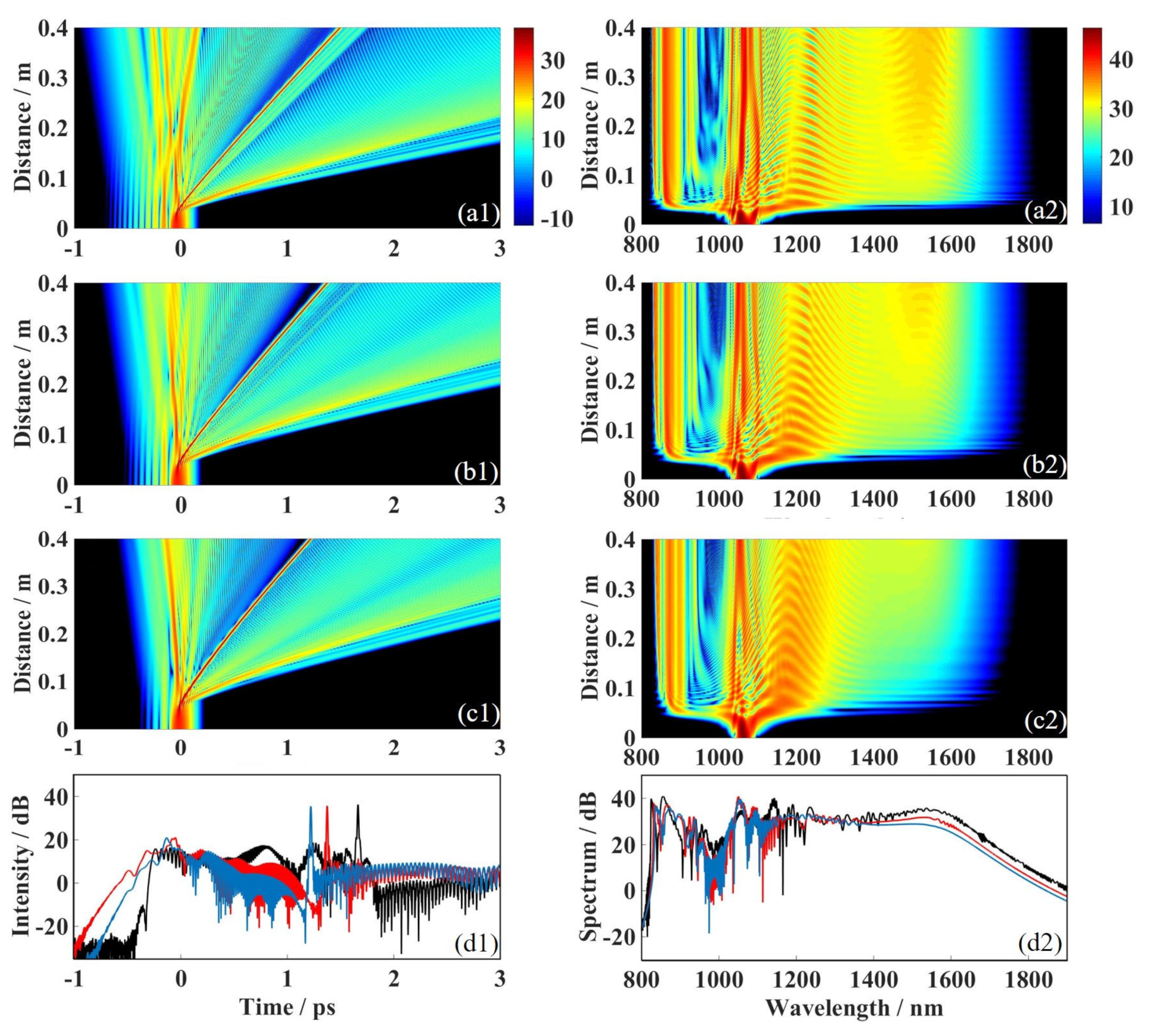
The truncation coefficient a is a degree of freedom to control the waveform of the Airy-Gaussian pulse. Numerical simulation is carried out to explore the influence of the truncation coefficient on the supercontinuum spectrum generated by the Airy-Gaussian pulse. From the time domain evolution diagram (Figure 4(a1–c1)), the Airy-Gaussian pulse is a multi-peak structure, and the truncation coefficient a can control the energy of the side lobe; when the truncation coefficient a is 0.15, the Airy pulse produces many oscillating trailing side lobes (Figure 4(a1)); and when it increases, the sidelobe of the trailing part of the pulse oscillation decreases rapidly, while the total energy of the pulse remains unchanged, that is, the trailing sidelobe energy is transferred to the main peak (Figure 4(b1,c1)). High-order dispersion and Kerr nonlinearity affect the Airy-Gaussian pulse transmitted in PCF2. The nonlinear effect is also greater for the Airy-Gaussian pulse with a larger truncation coefficient due to the larger energy proportion of its main peak. In addition, the deflection effect of higher-order dispersion on the higher-order soliton generated by the main peak will be smaller. From the frequency domain evolution diagram (Figure 4(b2,c2)), when the truncation coefficient a = 0.15, the width of the supercontinuum spectrum split by the Airy-Gaussian pulse is the largest (Figure 4(a2)). As the truncation coefficient increases to 0.5, the width of the split supercontinuum spectrum gradually decreases (Figure 4(a2–c2)). It is worth noting that when the truncation coefficient a = 0.5, the width of the supercontinuum generated by the Airy-Gaussian pulse gradually increases with the increase in the transmission distance and finally stabilizes at a fixed value. From the above analysis, we can control the supercontinuum width generated by the pulse by selecting different truncation coefficients. With the increase in the truncation coefficient, we can see that in the waveform (Figure 4(d1)) and spectrum (Figure 4(d2)) of the Airy-Gaussian pulse at a transmission distance of 0.4 m, the linear deflection of the time-domain shedding soliton decreases, and the width of the frequency-domain supercontinuum also decreases.
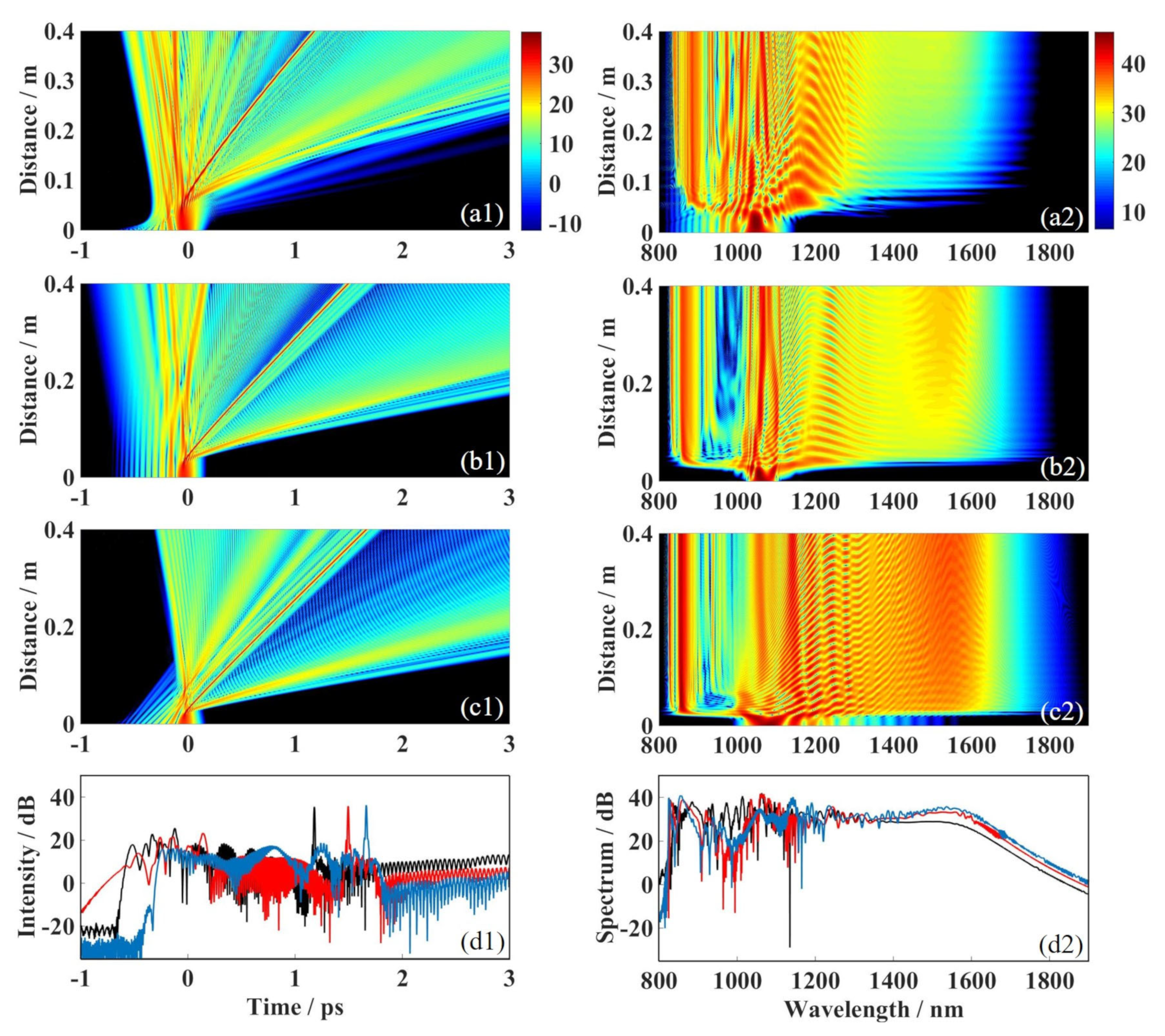
The distribution factor χ0 is another degree of freedom to control the Airy-Gaussian pulse waveform. A numerical simulation study was performed to explore the influence of the distribution factor on the supercontinuum spectrum generated by the Airy-Gaussian pulse. From the time domain evolution diagram (Figure 5(b1–d1)), the Airy-Gaussian pulse shows a multi-peak structure, and the distribution factor χ0 and the truncation coefficient a can also control the energy of the side lobe. When χ0 is 0.1, the Airy pulse has a small number of oscillating trailing side lobes [such as Figure 5(a1)]; when χ0 increases, the sidelobe of the trailing part of the pulse oscillation increases rapidly, while the total energy of the pulse remains unchanged, that is, the trailing sidelobe energy is transferred to the sidelobe (Figure 5(b1,c1)). Airy-Gaussian pulses are affected by both high-order dispersion and Kerr nonlinear effects when propagating in PCF2. For Airy-Gaussian pulses with a larger distribution factor, due to the smaller energy proportion of the main peak, the nonlinear effect is smaller, and the higher-order dispersion has a greater deflection effect on the higher-order solitons generated by the main peak. From the frequency domain evolution diagram, when the truncation coefficient χ0 is 0.05, the width of the supercontinuum generated by the Airy-Gaussian pulse is stable at 608 nm (Figure 5(a2)). As the distribution factor increases, the width of the generated supercontinuum spectrum changes (Figure 5(b2,c2)). It is worth noting that with the increase in the distribution factor, the width of the supercontinuum generated by the Airy-Gaussian pulse in PCF2 does not increase monotonously. The above analysis shows that the width of the supercontinuum generated by the Airy-Gaussian pulse can be maximized by selecting the appropriate distribution factor.
The initial chirp C is a degree of freedom to control the Airy-Gaussian pulse waveform. Numerical simulation is carried out to explore the influence of the initial chirp on the supercontinuum generation of the Airy-Gaussian pulse. From the time domain evolution diagram (Figure 6(a1–c1)), the initial chirp does not affect the initial waveform of the Airy-Gaussian pulse. However, with the increase in the transmission distance, the negative chirp increases the side lobe group velocity of the Airy-Gaussian pulse, and the waveform is elongated in the time domain (Figure 6(a1)). The positive chirp decreases the sidelobe velocity, which is manifested in the time domain as the waveform is compressed (Figure 6(c1)). In addition, the positive chirp leads to a decrease in the deflection angle of the Airy-Gaussian pulse, while the negative chirp leads to an increase in the deflection angle of the Airy-Gaussian pulse (Figure 6(a1,c1)). From the frequency domain evolution diagram, the initial chirp will affect the initial spectrum structure of the Airy-Gaussian pulse when C = 0, the initial spectrum of the Airy-Gaussian pulse is a bell-shaped structure symmetrically distributed at the central wavelength (Figure 6(c2)). The negative chirp transfers the central energy to the short wavelength side, forming a post-tail (Figure 6(a2)). The positive chirp will transfer the spectral energy at the central wavelength to the long wavelength side, forming a pre-oscillation tail (Figure 6(c2)). The larger the absolute value of the chirp, the longer the tail length. The negative chirp leads to the energy transfer to the short wavelength side, which reduces the width of the blue-shifted DW, but also fills the collapsed structure of the DW and the central higher-order soliton and improves the flatness of the supercontinuum. The positive chirp leads to energy transfer to the long wavelength side so that the width of the long wavelength side of the supercontinuum spectrum increases sharply. The positive chirp can broaden the spectrum to thousands of nanometers, but the supercontinuum flatness is very poor, seriously affecting the supercontinuum spectrum’s availability. Therefore, the value of the initial chirp should not be too large.
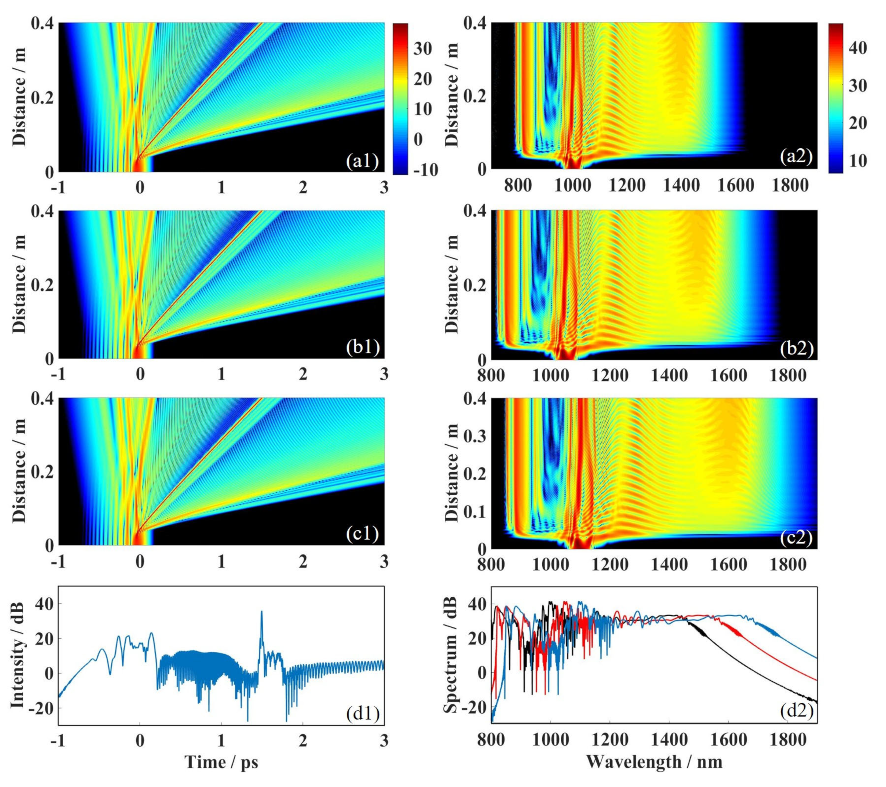
The center wavelength of the initial Airy-Gaussian pulse significantly affects its supercontinuum formation in photonic crystals. We selected four different center wavelengths for numerical simulation to further study the influence of the initial center wavelength on the supercontinuum spectrum formed by Airy-Gaussian pulses. From the time domain evolution diagram (Figure 7(a1–c1)), the initial chirp does not affect the initial waveform of the Airy-Gaussian pulse. When the center wavelength λ = 1000 nm (Figure 7(a1)), the higher-order dispersion of PCF2 leads to higher-order solitons generated from its main peak and deflected. When the center wavelength increases (Figure 7(a2,a3)), the higher-order dispersion of PCF2 increases, leading to a more pronounced deflection effect of the higher-order soliton generated by the main peak. The higher-order dispersion from the frequency-domain evolution diagram leads to a dramatic spectral broadening of the Airy-Gaussian pulse when the central wavelength λ = 1000 nm (Figure 7(a2)). The width of the supercontinuum spectrum increases significantly as the center wavelength increases (Figure 7(b2,c2)). The waveform plot (Figure 7(d1)) and the spectrogram (Figure 7(d2)) also show the above pattern. Through the above analysis, the Airy-Gaussian pulse can produce a broader supercontinuum spectrum by selecting the appropriate center wavelength.

3.4. The Detailed Process of the Supercontinuum Formation of Airy-Gaussian Pulse in PCF2

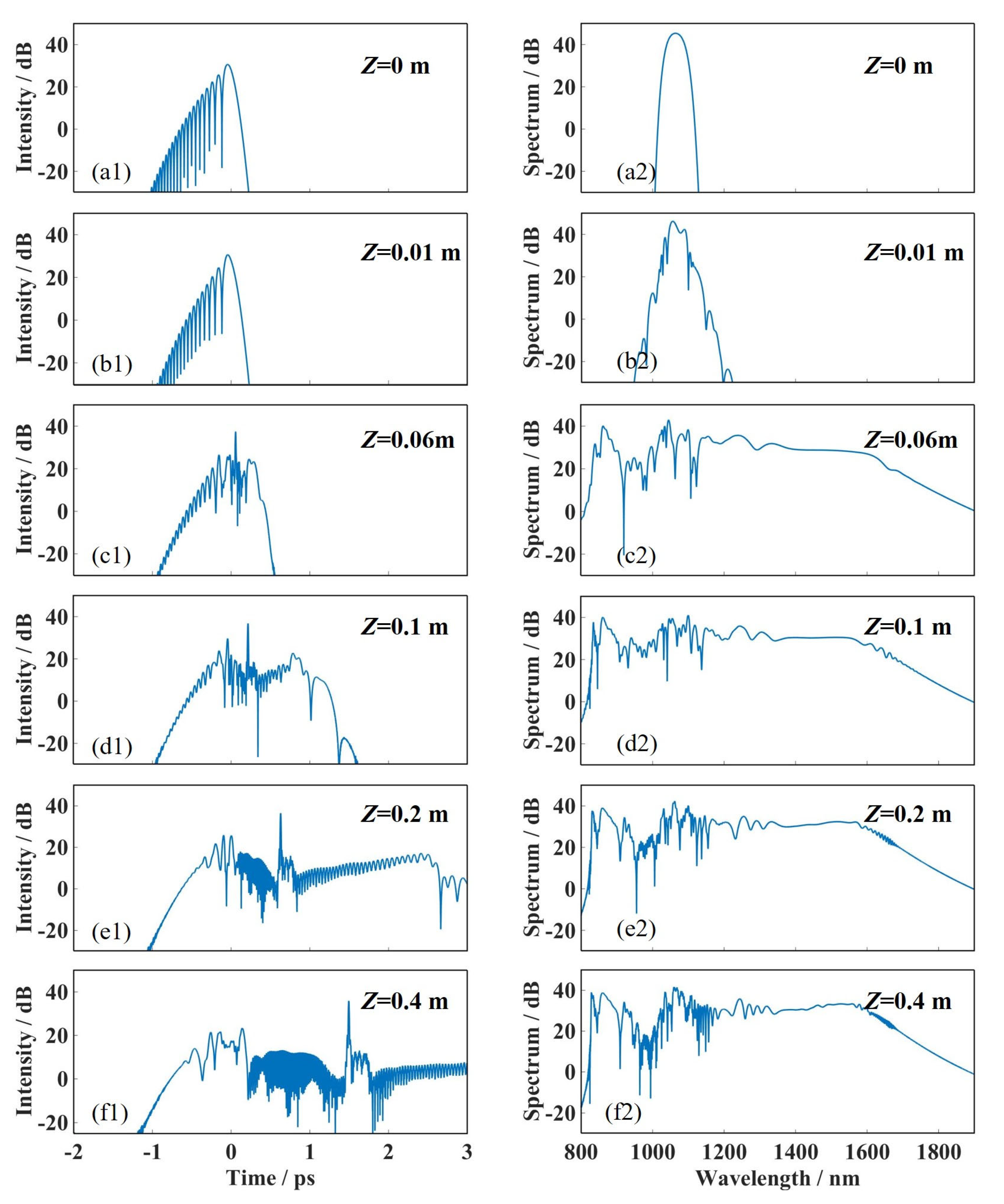
In this part, the transmission characteristics of the Airy-Gaussian pulse in PCF2 are analyzed in detail. The center wavelength of the Airy-Gaussian pulse is 1064 nm, the pulse width is 0.05 ps, the medium length is 0.4 m, P0 = 5 kW, a = 0.3, C = 0 and χ0 = 0.15. Figure 8 shows the waveform and spectrum evolution of the Airy-Gaussian pulse through six different transmission distances. It can be seen from the time-domain waveform that the main peak and a few side lobes of the Airy-Gaussian pulse undergo a process of soliton splitting and linear deflection (Figure 8(a1–f1)). When the transmission distance is about 0.06 m, the pulse completes the compression process, and the Airy-Gaussian pulse generates many high-energy solitons. Then, the solitons split, resulting in a sharp increase in the spectral width and the generation of DW in the short wavelength region (Figure 8(c2)). The central wavelength region of the pulse is in the normal dispersion region, and the high-order solitons will further split, while the short wavelength is in the strange dispersion region, and a certain blue-shifted dispersion wave will be generated (Figure 3(d2)). When the generated higher-order solitons are at their most numerous, and the DW is broadened to the maximum, the Airy-gaussian pulse reaches the saturation width of the supercontinuum spectrum and transmits stably. At 0.1 m, the frequency reaches the junction of R2 and R3 and enters R3 as R-DW (Figure 8(d2)). The R-DW in R3 forms an energy channel, continuously transferring energy to the tunneling soliton in R4, and the soliton spectral tunneling effect is completed (Figure 8(e2)). However, as the transmission distance increases, the degree of spectral broadening decreases significantly (Figure 8(f2)). When the propagation distance of the pulse in the PCF reaches a certain value, the width of the supercontinuum spectrum gradually decreases. This shows that as the fiber length increases, the spectral width also increases. However, when the fiber length continues to increase, the spectral width decreases and the flatness of the spectrum becomes worse. This is because when the pulse is transmitted in the optical fiber, the pulse width will be broadened and the peak power will be reduced accordingly, thus weakening the self-phase modulation effect of spectral broadening. Therefore, under the given input pulse condition, there is a limit to the value of the effective broadening length.

4. Conclusions

When the pulse propagates in the PCF with three zero-dispersion points, the spectral width becomes longer due to the red-shift dispersion, and the tunneling soliton effect occurs further, resulting in a broader supercontinuum spectrum than that of PCF with a one and two zero-dispersion points. In addition, compared with the traditional Gaussian pulse, the Airy-Gaussian pulse with two parameters (the truncation coefficient and the distribution factor) can control the width and spectral range of the supercontinuum spectrum more flexibly. Therefore, further research was conducted on the formation mechanism of supercontinuum spectra of Airy-Gaussian pulses in PCF with three zero-dispersion points. It is found that when the width of the barrier is less than the threshold, the red-shifted dispersion wave and tunneling soliton will be formed in R3. When the barrier width continues to widen and exceeds the threshold, soliton-like pulses may appear in R4, which are leaky dispersion waves or tunneling solitons. When the barrier width is too wide, the energy of the initial soliton is almost unable to pass through the barrier region, and most of the energy exists in the form of red-shifted dispersion waves in R3. Therefore, reasonable adjustment of the barrier can better control the soliton tunneling and the width and flatness of the supercontinuum spectrum generated by the soliton. In addition, the smaller the truncation coefficient and distribution factor of the Airy-Gaussian pulse in the PCF with three zero-dispersion points, the larger the initial chirp and the central wavelength, and a broader the supercontinuum spectrum can be obtained. Tunneling solitons formed by Airy-Gaussian pulses in PCF with three zero-dispersion wavelengths can maintain a stable shape.

Author Contributions

Data curation, X.Y. and B.W.; methodology, Y.D., C.G. and J.W.; software, S.Z. and Q.Z. All authors have read and agreed to the published version of the manuscript.

Funding

This research was funded by the Natural Science Foundation of Hunan Province under grant numbers 2022JJ50276 and 2023JJ50352, and the Scientific Research Fund of Hunan Provincial Education Department under grant numbers 22A0560 and 21A0499.

Institutional Review Board Statement

Not applicable.

Informed Consent Statement

Not applicable.

Data Availability Statement

Not applicable.

Conflicts of Interest

The authors declare no conflict of interest.

References

  1. Siviloglou, G.A.; Christodoulides, D.N. Accelerating finite energy Airy beams. Opt. Lett. 2007, 32, 979–981. [Google Scholar] [CrossRef] [PubMed]
  2. Siviloglou, G.A.; Broky, J.; Dogariu, A.; Christodoulides, D.N. Observation of Accelerating Airy Beams. Phys. Rev. Lett. 2007, 99, 213901. [Google Scholar] [CrossRef] [PubMed]
  3. Kaminer, I.; Bekenstein, R.; Nemirovsky, J.; Segev, M. Nondiffracting Accelerating Wave Packets of Maxwell’s Equations. Phys. Rev. Lett. 2012, 108, 163901. [Google Scholar] [CrossRef] [PubMed]
  4. Broky, J.; Siviloglou, G.A.; Dogariu, A.; Christodoulides, D.N. Self-healing properties of optical Airy beams. Opt. Exp. 2008, 16, 12880–12891. [Google Scholar] [CrossRef] [PubMed]
  5. Ellenbogen, T.; Voloch-Bloch, N.; Ganany-Padowicz, A.; Arie, A. Nonlinear generation and manipulation of Airy beams. Nat. Photonics 2009, 3, 395–398. [Google Scholar] [CrossRef]
  6. Christodoulides, D.N. Optical trapping: Riding along an Airy beam. Nat. Photonics 2008, 2, 652–653. [Google Scholar] [CrossRef]
  7. Christodoulides, D.N. Airy plasmon: A nondiffracting surface wave. Opt. Lett. 2010, 35, 2082–2084. [Google Scholar]
  8. Polynkin, P.; Kolesik, M.; Moloney, J.V.; Siviloglou, G.A.; Christodoulides, D.N. Curved Plasma Channel Generation Using Ultraintense Airy Beams. Science 2009, 324, 229–232. [Google Scholar] [CrossRef]
  9. Minovich, A.; Klein, A.E.; Janunts, N.; Pertsch, T.; Neshev, D.N.; Kivshar, Y.S. Generation and near-field imaging of Airy surface plasmons. Phys. Rev. Lett. 2011, 107, 116802. [Google Scholar] [CrossRef]
  10. Deng, D.; Li, H. Propagation properties of Airy–Gaussian beams. Appl. Phys. B 2012, 106, 677–681. [Google Scholar] [CrossRef]
  11. Li, P.; Malomed, B.A.; Mihalache, D. Symmetry breaking of spatial Kerr-solitons in fractional dimension. Chaos Solitons Fract. 2020, 132, 109602. [Google Scholar] [CrossRef]
  12. Zeng, L.W.; Malomed, B.A.; Mihalache, D.; Cai, Y.; Lu, X.W.; Zhu, Q.F.; Li, J.Z. Bubbles and W-shaped solitons in Kerr media with fractional diffraction. Nonlinear Dyn. 2021, 104, 4253–4264. [Google Scholar] [CrossRef]
  13. Xiao, Y.; Zhang, J.; Wang, P.X. Periodic evolution of Airy-Gaussian beams under linear potential. Chin. J. Lasers 2021, 48, 105002. [Google Scholar] [CrossRef]
  14. Chen, W.J.; Song, D.; Li, Y.; Wang, X.; Qin, X.L.; Liu, C.Y. Control on interaction of Airy-Gaussian beams in competing no nlinear medium. Acta Phys. Sin. 2019, 68, 94206. [Google Scholar] [CrossRef]
  15. Zhang, L.F.; Liu, K.; Zhong, H.Z.; Zhang, J.G.; Li, Y.; Fan, D.Y. Effect of initial frequency chirp on Airy pulse propagation in an optical fiber. Opt. Express 2015, 23, 2566–2576. [Google Scholar] [CrossRef] [PubMed]
  16. Zhang, L.F.; Zhong, H.Z. Modulation instability of finite energy Airy pulse in optical fiber. Opt. Express 2014, 22, 17107–17115. [Google Scholar] [CrossRef]
  17. Zhang, L.F.; Zhong, H.Z.; Li, Y.; Fan, D.Y. Manipulation of Raman-induced frequency shift by use of asymmetric self-accelerating Airy pulse. Opt. Express 2014, 22, 22598–22607. [Google Scholar] [CrossRef] [PubMed]
  18. Chen, C.D.; Chen, B.; Peng, X.; Deng, D.M. Propagation of Airy-Gaussian beam in Kerr medium. J. Opt. 2015, 17, 35504. [Google Scholar] [CrossRef]
  19. Liu, Y.; Wu, L.; Xu, C.; Deng, D. Propagation and Wigner distribution of the Airy–Gauss beam through an apertured paraxial optical system. Opt. Commun. 2020, 454, 124494. [Google Scholar] [CrossRef]
  20. Ranka, J.K.; Windeler, R.S.; Stentz, A.J. Visible continuum generation in air–silica microstructure optical fibers with anomalous dispersion at 800 nm. Opt. Lett. 2000, 25, 25–27. [Google Scholar] [CrossRef]
  21. Ranka, J.K.; Windeler, R.S.; Stentz, A.J. Nonlinear wavelength conversion in photonic crystal fibers with three zero-dispersion points. Phys. Rev. A 2011, 83, 23808. [Google Scholar]
  22. Barak, A.; Peleg, O.; Stucchio, C.; Segev, M. Observation of Soliton Tunneling Phenomena and Soliton Ejection. Phys. Rev. Lett. 2008, 100, 153901. [Google Scholar] [CrossRef] [PubMed]
  23. Tsoy, E.N.; De Sterke, C.M. Theoretical analysis of the self-frequency shift near zero-dispersion points: Soliton spectral tunneling. Phys. Rev. A 2007, 76, 43804. [Google Scholar] [CrossRef]
  24. Bache, M.; Bang, O.; Zhou, B.; Moses, J.; Wise, F.W. Optical Cherenkov radiation by cascaded nonlinear interaction: An efficient source of few-cycle energetic near- to mid-IR pulses. Opt. Express 2011, 19, 22557–22562. [Google Scholar] [CrossRef] [PubMed]
  25. Wang, S.F.; Hu, J.G.; Guo, H.R.; Zeng, X.L. Optical Cherenkov radiation in an As2S3 slot waveguide with four zero-dispersion wavelengths. Opt. Express 2013, 21, 3067–3072. [Google Scholar] [CrossRef] [PubMed]
  26. Gonzalez-Baquedano, N.; Torres-Gomez, M.; Arzate, N.; Ferrando, A.; Ceballos-Herrera, D.E. Pulse quality analysis on soliton pulse compression and soliton self-frequency shift in a hollow-core photonic bandgap fiber. Opt. Express 2013, 21, 9132–9143. [Google Scholar] [CrossRef] [PubMed]
  27. Li, H.Z.; Cai, W.Y.; Zhang, J.; Gao, Y.X.; Zhang, L.F.; Fan, D.Y. Manipulation of dispersive waves emission via quadratic spectral phase. Opt. Express 2021, 29, 12723–12735. [Google Scholar] [CrossRef] [PubMed]
  28. Peng, W.L.; Zhang, X.; Jing, L.Q.; Gao, Y.X.; Deng, Z.X.; Zhang, L.F.; Fan, D.Y. Soliton-sinc optical pulse propagation in the presence of high-order effects. Opt. Express 2023, 31, 9961–9972. [Google Scholar] [CrossRef]
  29. Li, H.Z.; Wang, Z.T.; Xie, Z.X.; Fan, D.Y.; Zhang, L.F. Manipulating dispersive wave emission via temporal sinusoidal phase modulation. Opt. Express 2023, 31, 6296–6303. [Google Scholar] [CrossRef]
  30. Ouahid, L.; Dalil, E.L.; Belafhal, A. Effect of light absorption and temperature on self-focusing of finite Airy Gaussian beams in plasma with relativistic and ponderomotive regime. Quantum Electron. 2018, 50, 216–232. [Google Scholar] [CrossRef]
  31. Marest, T.; Braud, F.; Conforti, M.; Wabnitz, S.; Mussot, A.; Kudlinski, A. Longitudinal soliton tunneling in optical fiber. Opt. Lett. 2017, 42, 2350–2353. [Google Scholar] [CrossRef]
  32. Peng, H.Y.; Li, Y.; Peng, J.; Wen, B.; Deng, Y.B.; Tang, P.H. Evolution of Airy-Gaussian pulses in photonic crystal fiber with two zero-dispersion wavelengths. Optik 2021, 250, 168324. [Google Scholar] [CrossRef]
  33. Luo, Y.P.; Yang, H.; Zhao, S.L.; Lv, J.; Hu, H. Impact of potential barriers on soliton spectral tunneling in photonic crystal fiber. Opt. Commun. 2020, 454, 124330. [Google Scholar] [CrossRef]
  34. Li, Y.; Peng, J.; Tan, C.; Tang, P.H. Numerical investigation on the dynamic propagation of finite-energy Airy pulses in photonic crystal fiber. J. Mod. Opt. 2020, 67, 445–453. [Google Scholar] [CrossRef]
Figure 1. (a) Typical curves of dispersion profile and (b) the dispersion profiles curves of PCF1 (black curve), PCF2 (red curve), PCF3 (blue curve) and PCF4 (green curve); these PCFs have the same first and second zero-dispersion points at 771 nm and 924 nm, but when it turns to the third zero-dispersion point, PCF1 is 974 nm, PCF2 is 1014 nm, PCF3 is 1064 nm and PCF4 is 1109 nm.
Photonics 10 01061 g001
Figure 2. When P0 = 5 kW, a = 0.1, χ0 = 0.1 and C = 0, λ = 1064 nm, the spectral evolution of Airy-Gaussian pulse in PCFs with four different barrier widths are studied. (a) PCF1; (b) PCF2; (c) PCF3; (d) PCF4.
Photonics 10 01061 g002
Figure 3. When P0 = 5 kW, a = 0.1, χ0 = 0.1 and C = 0, λ = 1064 nm, the spectral evolution process of Airy-Gaussian pulse in PCFs with a different number of zero dispersion points is studied: (a) single zero-dispersion point, (b) two zero-dispersion points and (c) three zero-dispersion points.
Photonics 10 01061 g003
Figure 4. When P0 = 5 kW, C = 0, χ0 = 0.1, λ = 1064 nm, the time domain and frequency domain evolution of Airy-Gaussian pulses with different truncation coefficients an in PCF2 are studied. Among them, (a1,a2) a = 0.2, (b1,b2) a = 0.35, and (c1,c2) a = 0.5. (d1,d2) represents the waveform and spectrum corresponding to a = 0.15 (black line), a = 0.35 (red line) and a = 0.5 (blue line) when the transmission distance is 0.4 m.
Photonics 10 01061 g004
Figure 5. When P0 = 5 kW, a = 0.5, C = 0, λ = 1064 nm, the time domain and frequency domain evolution of Airy-Gaussian pulses with different distribution factors χ0 in PCF2 are studied. Among them, (a1, a2) χ0 = 0.05, (b1,b2) χ0 = 0.25 and (c1,c2) χ0 = 0.45. (d1,d2) represents the waveform and spectrum corresponding to the distribution factors of χ0 = 0.05 (black line), χ0 = 0.25 (red line) and χ0 = 0.45 (blue line) when the transmission distance is 0.4 m.
Photonics 10 01061 g005
Figure 6. When P0 = 5 kW, a = 0.1, χ0 = 0.03 and λ = 1064 nm, the time domain and frequency domain evolution of Airy-Gaussian pulses with different initial chirp C in PCF2 are studied. Where (a1,a2) C = −0.3, (b1,b2) C = 0 and (c1,c2) C = 0.3. (d1,d2) represents the corresponding waveforms and spectrograms when the initial chirps are C = −0.3 (black line), C = 0 (red line) and C = 0.3 (blue line), respectively, when the transmission distance is 0.4 m.
Photonics 10 01061 g006
Figure 7. When P0 = 5 kW, a = 0.1, χ0 = 0.03 and C = 0, the time domain and frequency domain evolution of Airy-Gaussian pulses with different initial center wavelengths λ in PCF2. Here, (a1,a2) λ = 1000 nm, (b1,b2) λ = 1050 nm and (c1,c2) λ = 1100 nm. (d1,d2) represent the waveforms and spectrograms corresponding to the initial chirps of λ = 1000 nm (black line), λ = 1000 nm (red line) and λ = 1000 nm (blue line) when the transmission distance is 0.4 m.
Photonics 10 01061 g007
Figure 8. The waveforms (a1f1) and spectra (a2f2) of Airy-Gaussian pulses with different transmission distances in PCF2.
Photonics 10 01061 g008
Table 1. Dispersion parameters of PCFs with different three zero-dispersion points.
pskPCFs with Three Zero-Dispersion Points
k1234
2−15.8126−15.8126−15.8126−15.8126
30.100250.110250.110250.13025
41.0582 × 10−31.0382 × 10−30.9682 × 10−31.0382 × 10−3
5−1.5686 × 10⁻⁶−1.5686 × 10⁻⁶−1.5686 × 10⁻⁶−1.5686 × 10⁻⁶
62.4280 × 10−92.4280 × 10−92.4280 × 10−92.4280 × 10−9
74.0260 × 10−102.1260 × 10−100.5260 × 10⁻¹⁰−0.3260 × 10⁻¹⁰
8−1.7693 × 10⁻¹²−1.7693 × 10⁻¹²−1.7693 × 10⁻¹²−1.7693 × 10⁻¹²
96.4322 × 10−156.4322 × 10−156.4322 × 10−156.4322 × 10⁻¹⁵
103.1990 × 10−203.1990 × 10−203.1990 × 10−203.1990 × 10⁻²⁰
Disclaimer/Publisher’s Note: The statements, opinions and data contained in all publications are solely those of the individual author(s) and contributor(s) and not of MDPI and/or the editor(s). MDPI and/or the editor(s) disclaim responsibility for any injury to people or property resulting from any ideas, methods, instructions or products referred to in the content.