Abstract
In this work, we investigated the effects of different acceptors (IT−4F and PC71BM) on the charge dynamics in PM6-based solar cells. The correlation between different acceptors and the performance of organic solar cells was studied by atomic force microscope, steady-state absorption spectrum, transient absorption spectrum, and electrical measurements. Optical absorption exhibited that IT−4F has strong absorption in the near-infrared region for the active layer. Transient absorption measurements showed that different acceptors (IT−4F and PC71BM) had a significant influence on the behaviors of PM6 excitons and charge dynamics. That is, the exciton dissociation rate and delocalized polaron transport in the PM6:IT−4F active layer were significantly faster than that in the PM6:PC71BM active layer. The lifetime of localized polaron in the PM6:PC71BM active layer was longer than that in the PM6:IT−4F active layer. Conversely, the lifetime of delocalized polaron in the PM6:IT−4F active layer was longer than that in the PM6:PC71BM active layer. Electrical measurement analysis indicated that lower bimolecular recombination, higher charge transport, and charge collection ability were shown in the PM6:IT−4F device compared with the PM6:PC71BM device. Therefore, PM6:IT−4F solar cells achieved a higher power conversion efficiency (12.82%) than PM6:PC71BM solar cells (8.78%).
1. Introduction
Organic solar cells (OSCs) are one of the highlights in the photovoltaic energy field because of their unique advantages in flexibility, foldability, large-area, and low-cost fabrication, as well as building-integrated photovoltaics [1,2,3,4]. Therefore, they have been highly concerned by governments and energy groups all over the world [5,6,7]. Recently, the power conversion efficiency (PCE) of high−efficient OSCs has already reached more than 18%, or even a breakthrough of 20% [8], showing a bright application prospect. Up to now, the improved efficiency of OSCs usually is attributed to many aspects, such as synthesis of the new donor (D) and acceptor (A) materials, morphology optimization, ternary and layer-by-layer strategies, interface engineering and fabrication process [9,10,11,12,13,14,15,16,17,18]. Among them, the high-efficient materials are considered the most fundamental reason for continuously promoting the efficiency of OSCs. At present, PM6, D18, PTQ10, PY−IT, IT−4F, Y−series, L8−BO, BTP−eC9, and PC71BM are representative donor and accepter materials for OSCs [19,20,21,22,23,24,25].
The photoelectric conversion process in OSCs usually shows more complex compared with silicon-based solar cells due to their low dielectric constant and blended structure of active layer [26,27]. In general, the active layer of OSCs is composed of a bulk−heterojunction (BHJ) structure, that is, a film of blended D:A materials. Exciton species will be generated after the active layer absorbs the photon energy and then diffuse to the interface of the D/A interface for dissociation (or charge transfer) [28]. Subsequently, hole and electron transport separately in the donor phase and acceptor phase. However, exciton diffusion and dissociation, charge generation, and transport can not be fully utilized for the conversion of photon to charge in this BHJ structure because of exciton recombination and charge recombination. Hence, the power conversion efficiency of OSCs is dramatically related to the absorption efficiency of materials (ηA), diffusion and dissociation efficiency of excitons (ηED), charge transport efficiency (ηCT), and charge collection efficiency (ηCC) [29,30]. For achieving high-performance OSCs, it is necessary to effectively facilitate the conversion efficiency of these processes. Obviously, these η are determined by the composition of the active layer and the configuration of the device. For instance, in terms of D:A composition, the classical donor material, PM6, could achieve different PCE values when it blended with IT−4F, PC71BM, Y6, or L8−BO at the same preparation conditions [31,32,33,34]. This information indicates that photoelectric conversion behaviors are different in these PM6:acceptor solar cells. If the relevance between the D:A materials and their device performance can be effectively elucidated, that will help us to further develop the high-efficient OSCs.
In this work, the effects of fullerene derivative (PC71BM) and non-fullerene conjugated small molecule (IT−4F) on the photoelectric conversion process of PM6 were comparatively studied. To elucidate the intrinsic relationship between acceptor material and device performance, an atomic force microscope (AFM), steady-state absorption spectrum, transient absorption spectrum (TAS), and electrical measurements were carried out. Our results showed that PC71BM and IT−4F would lead to different optical absorption abilities and BHJ morphology for the PM6-based active layer, thereby determining the photogenerated charge processes of PM6. In addition, we also found the donor and acceptor phase scales in PM6:IT−4F showed more refined phase size and phase separation degree, which made the dissociation rate of excitons and charge generation and transport ability in this active layer better than that in PM6:PC71BM. Electrical analysis indicated that the PM6:IT−4F device had a lower bimolecular recombination a higher charge transport and charge collection ability than the PM6:PC71BM device. Therefore, the performance output of the PM6:IT−4F solar cell is superior to the PM6:PC71BM solar cell.
2. Materials and Methods
2.1. Materials and Device Fabrication
Organic photovoltaic materials PM6, IT−4F, and PC71BM were all purchased from Solarmer (Beijing, China). Their molecular and energy level structures are drawn in Figure 1. The ITO glass was purchased from Shenzhen South China Xiangcheng Technology Co., Ltd. (Shenzhen, China). The square resistance and transmittance are ≤7 Ohm and ≥84% (500−700 nm), respectively. The structure of OSCs followed the configuration of ITO/ZnO/active layer/MoO3/Ag. The preparation process of the OSCs was as follows. First, ITO glass was successively ultrasonicated in acetone, chloroform, ethanol, and isopropanol for 10 min. Then, a precursor solution, zinc acetate/2-methoxyethanol/ethanolamine (1 g:10 mL:0.28 mL), with a dose of 60 µL, was spin-coated on the surface of ITO glass. After that, the film needed to be annealed at 200 °C for 1 h to form a layer of ~25 nm thick ZnO. An active layer solution (PM6:IT−4F or PM6:PC71BM in a mass ratio of 1:1, with a total concentration of 20 mg/mL dissolved in a binary solvent of chlorobenzene (99.5%) and 1,8-diiodooctane (0.5%), and stirred at 400 rpm, 40 °C for at least 8 h) was spin-coated on ZnO layer. The thickness of the two active layers was around 100 nm by adjusting the speed and time of spin coating. The thicknesses of ZnO and active layer were both measured by a step profiler (KLA−tencor, D-600, Milpitas, CA, USA). Afterward, the active layers were annealed on a 120 °C hot plate for 10 min to optimize their morphology. Finally, a layer of 8 nm MoO3 and a thickness of 100 nm Ag electrode were sequentially prepared by thermal evaporation on the surface of the active layer. The thicknesses of MoO3 and Ag were determined by a rate/thickness monitor (INFICON, SQM−160, Bad Ragaz, Switzerland).

Figure 1.
(a) Molecular structures and (b) energy level structures of PM6, IT−4F, and PC71BM.
2.2. Optical and Morphological Characterizations of Active Layer
Steady-state absorption spectra of active layers were tested by using a UV−Vis−NIR spectrometer (Agilent, Cary5000, Santa Clara, CA, USA). Morphology of the active layers was characterized by atomic force microscope (Agilent, AFM-5500, Santa Clara, CA, USA).
2.3. Electrical Measurement and Transient Absorption Spectroscopy
The linear sweep voltammetry (LSV) mode of the electrochemical workstation (Chenhua, CHI760E, Shanghai, China) was used to test the current–voltage curve of OSCs. During the testing process, a xenon lamp provided a power of 100 mW/cm2 to illuminate the OSCs. Electrochemical impedance spectroscopy (EIS) of the device was also measured by an electrochemical workstation under the light irradiation condition. External quantum efficiency (EQE) of OSCs was measured by a spectral response measurement system (Sofn Instruments, 7-DRSpec, Beijing, China) at room temperature in the air. The transient absorption spectrum of the active layer was characterized by using the HARPIA−TA spectroscopy system and PHAROS (1030 nm, pulse width ~190 fs, repetition rate 100 kHz, light conversion) as the basic laser source. The output of the laser source was divided into two beams. One of them was introduced into an optical parameter amplifier (OPA, optical conversion) and then used as a pump light. The other beam was used to generate the white light supercontinuum, which was used as the detection light for differential absorption measurement. The time delay of the pump-probe was controlled by a mechanical delay stage.
3. Results and Discussion
3.1. Photovoltaic Performance of OSCs
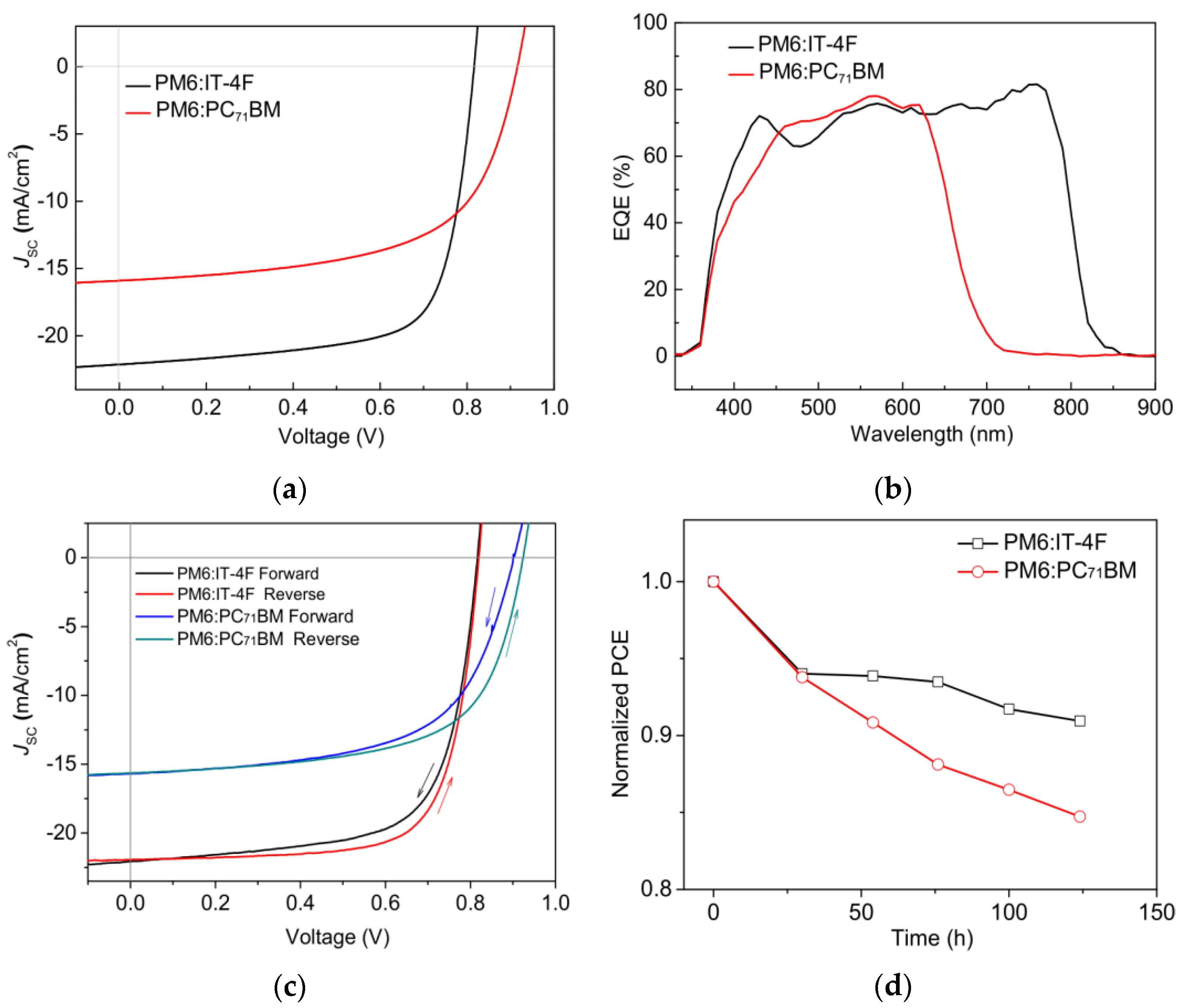
Figure 2a and Table 1 show the J-V characteristic curves and photovoltaic parameters of PM6:IT−4F and PM6:PC71BM solar cells, respectively. It can be seen that the open circuit voltage (VOC), short-circuit current density (JSC), fill factor (FF), and PCE of PM6:PC71BM solar cell are 0.916 V, 15.90 mA/cm2, 60.30%, and 8.78%, respectively. But for the PM6:IT−4F solar cell, the corresponding photovoltaic parameters are changed to 0.816 V, 22.13 mA/cm2, 71.02%, and 12.82%. Compared with the PM6:PC71BM solar cell, the PM6:IT−4F device with higher PCE is largely due to the enhanced JSC and FF. As for JSC, we investigated the EQE characteristics of two OSCs, as shown in Figure 2b. In the wavelength region of 700–850 nm, the EQE of the PM6:IT−4F solar cell is significantly stronger than that of the PM6:PC71BM solar cell. Because IT−4F shows an absorption band in this region (cf. Figure 3), which can effectively convert photons into photocurrent. As for the improved FF, we consider that it may be related to the morphology of active layers, which will be discussed later. However, the VOC parameter of the PM6:PC71BM solar cell performs higher (0.1 V) than the PM6:IT−4F device. This is related to the energy levels and ratios between the PM6 and acceptor. Therefore, the collocations of PM6:IT−4F and PM6:PC71BM have their advantages and disadvantages in performance output; thereby, many research groups adopted PM6:IT−4F:PC71BM as a ternary active layer to achieve the highly efficient OSCs [35]. To evaluate the quality of two devices, hysteresis index (HI) and device stability were analyzed, as shown in Figure 2c,d. The HI values were calculated with (PCEreverse − PCEforward)/PCEreverse [36], and their values were calculated as 5.8% (PM6:IT−4F) and 6.9% (PM6:PC71BM), respectively. The PCE values correspondingly decreased by 9% and 15% after 124 h (without encapsulation). Both the hysteresis index and PCE variation indicate that the PM6:IT−4F solar cell has better stability than the PM6:PC71BM solar cell.
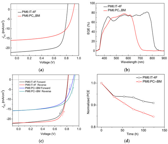
Figure 2.
(a) J−V curves and (b) EQE curves of PM6:IT−4F and PM6:PC71BM solar cells. (c) Forward and reverse scans of two OSCs, (d) Normalized PCE variations of two OSCs with time.

Table 1.
The averaged photovoltaic parameters based on PM6:IT−4F and PM6:PC71BM solar cells. The average and errors were calculated from 10 cells.
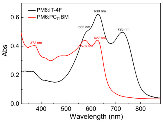
Figure 3.
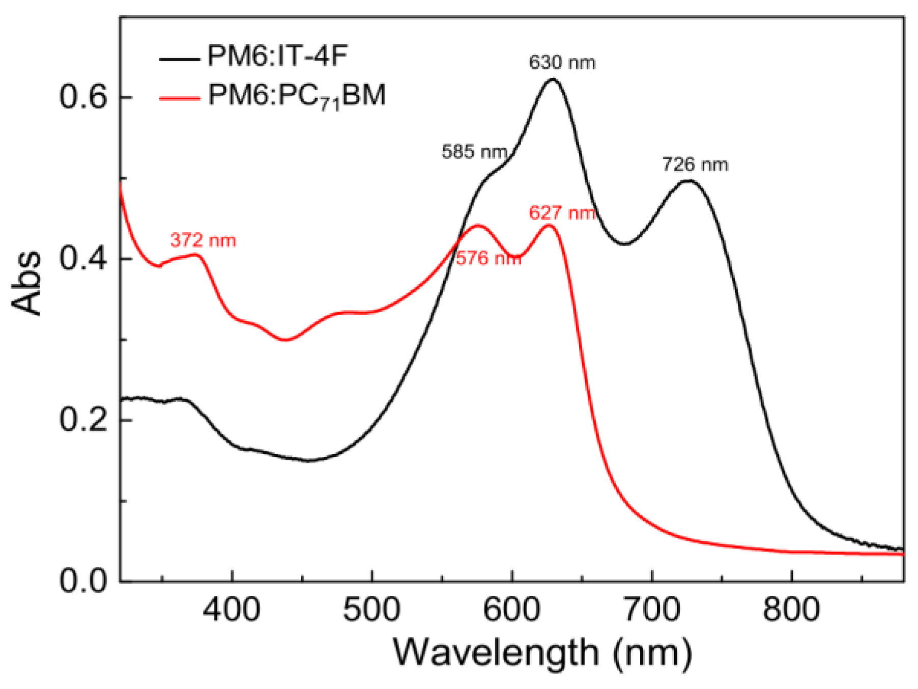
Steady−state absorption spectra of PM6:IT−4F and PM6:PC71BM active layers.
3.2. Absorption Spectra of Active Layers
The active layer is a core component of OSCs, which can convert the photons into charges. To investigate the effect of acceptors on the optical absorption characteristics of active layers, the steady-state absorption spectra of PM6:IT−4F and PM6:PC71BM were characterized by a UV−Vis−IR spectrometer, as shown in Figure 3. It can be seen that the main absorption band of PM6:IT−4F exhibits three consecutive characteristic absorption bands in the wavelength region of 300−820 nm, which are related to the synergistic absorption of PM6 and IT−4F [37]. But for the absorption of PM6:PC71BM, its absorption bands are shown in the wavelength region of 300−700 nm. While PM6 blends with IT−4F, it shows three peaks at 585 nm, 630 nm, and 726 nm (IT−4F); the first two peaks belong to PM6, which represents the aggregation state of the polymer [38]. However, these two peaks are blue-shifted to 576 nm and 627 nm in PM6:PC71BM film. This means that the aggregation degree of polymer in PM6:IT−4F blend film is better than that in PM6:PC71BM. Besides, we also observe that the absorption of PM6:IT−4F in the near-infrared range (650−820 nm) is significantly enhanced by IT−4F, which makes the absorption of this blend film match with the solar spectrum well [39]. As for PM6:PC71BM film, its absorption is enhanced in the near ultraviolet region (300−550 nm) due to the addition of PC71BM. Therefore, both IT−4F and PC71BM contribute to the enhancement of the light absorption capacity of the active layer.
3.3. Morphology of Active Layers
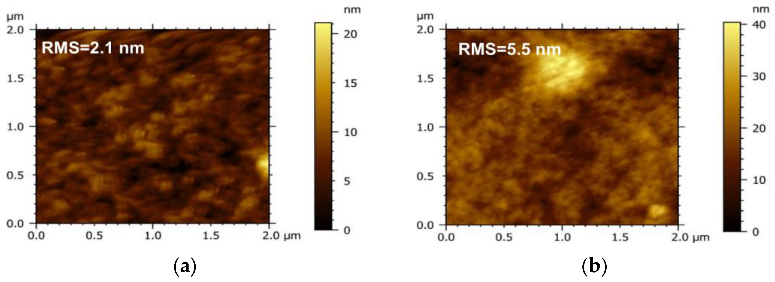
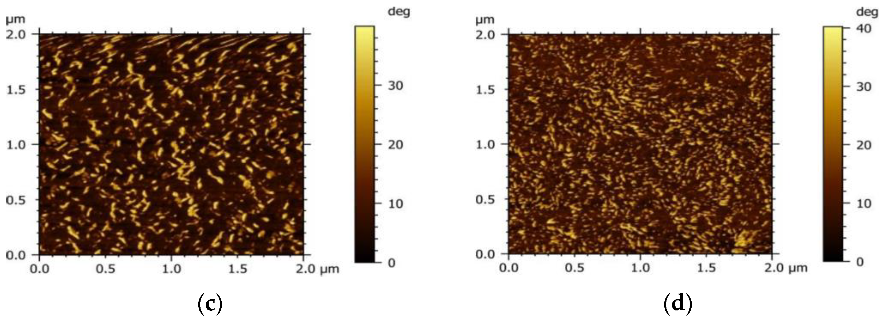
To investigate the influence of the acceptor on the morphology of the active layer, the micro-morphology of the PM6 blend with different acceptors (IT−4F or PC71BM) was characterized by the tapping mode of AFM, as shown in Figure 4. It can be seen that the surface roughness of the PM6:IT−4F is 2.1 nm (Figure 4a), while the surface roughness of the PM6:PC71BM increases to 5.5 nm (Figure 4b). The increased roughness means that the surface undulation is more obvious and also indicates that the flatness of the surface is weakened, which may reduce the Ohmic contact among the active layer, MoO3, and Ag electrode [40]. In addition, the active layer with smaller roughness usually represents the refined self−aggregation scales of the D and A phases (Figure 4c,d), which will facilitate the fast diffusion of the photogenerated exciton to the D/A interface for dissociation [41].
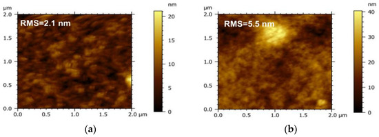
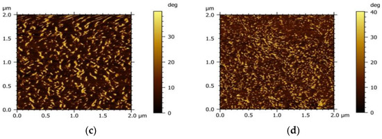
Figure 4.
Morphology of PM6:IT−4F and PM6:PC71BM active layers. The top is surface morphology, and the bottom represents phase morphology. (a,c), PM6:IT−4F, (b,d), PM6:PC71BM.
3.4. Transient Absorption Spectra of Active Layers
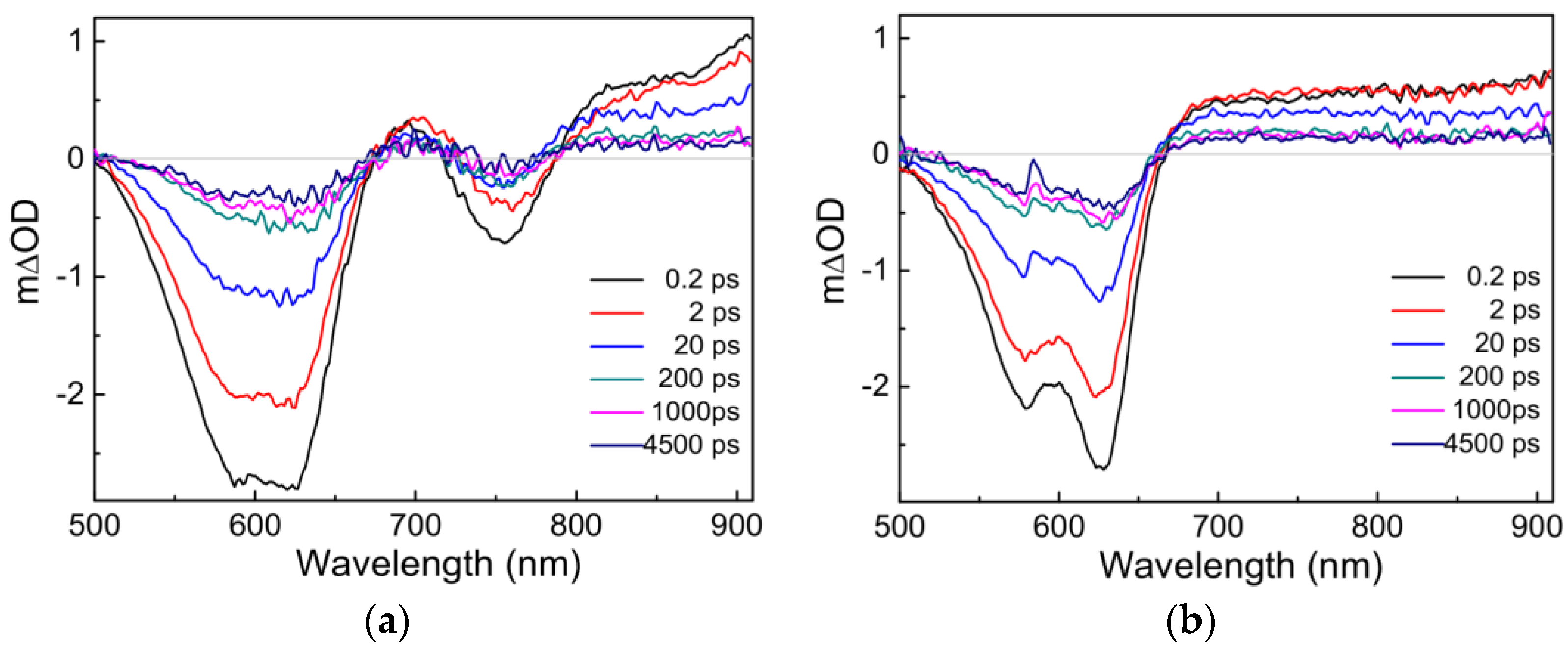
In general, the photoelectric conversion process in OSCs is significantly different and more complex than that in silicon-based solar cells [42]. To investigate the effects of different acceptors (IT−4F, PC71BM) on the charge photogenerated process of PM6, the transient absorption spectra of PM6:IT−4F and PM6:PC71BM were first analyzed, as seen in Figure 5. After photoexcitation, the TA spectra consist of two spectral bands: the negative spectral signal arising from ground-state bleach or stimulated emission and the positive spectral signal generated from photo-induced absorption [43]. Under the same conditions of photoexcitation, there are some differences in the transient spectra between PM6:IT−4F and PM6:PC71BM. Firstly, their ground-state bleach features are different from each other. The former (PM6:IT−4F) has an additional bleaching band in the wavelength region of 720−790 nm due to the absorption of IT−4F in the blend film (see Figure 3). Secondly, the dynamics of the photo-induced absorption spectra between two active layers are very different within 200 ps. However, it can be found that the photo-induced absorption spectral features of two active layers tend to be similar beyond 200 ps. Hence, we consider that the transient species are the same in PM6:IT−4F and PM6:PC71BM (>200 ps). Moreover, it can be determined this transient species still exists up to 4.5 ns. Such long-lived species are assigned to charged species (such as polaron) [44].
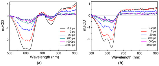
Figure 5.
Transient absorption spectra of (a) PM6:IT−4F and (b) PM6:PC71BM active layers. The excitation wavelength is 600 nm with a photoexcitation fluence of 1.8 × 10¹² photons cm−2 pulse−1.
Up to now, the mainstream view suggests that there are two types of sources for photogenerated charges [45,46]. One is the conversion of photogenerated charges from excitons, charge transfer excitons, etc. Another source is that transient charges are generated at the moment of photoexcitation. In our previous work [47], the steady-state absorption spectrum of PM6•+ (similar to electropositive transient species, polaron) was obtained by spectroelectrochemistry. Its absorption range was 650~1100 nm with three characteristic absorption peaks at ~680 nm, ~780 nm and ~900 nm, respectively. The first two absorption peaks (680 nm and 780 nm) were related to the ordered aggregation state of the polymer, which could be referred to as the delocalized polaron. The absorption peak of ~900 nm was related to the disordered aggregation of the polymer, and it could be confirmed as the localized polaron [46,48]. Herein, the photo-induced transient spectra signals of PM6:IT−4F and PM6:PC71BM within 200 fs (Figure 5) seemed different from the steady-state absorption spectrum of PM6•+. Accordingly, we consider that the dominant source of photogenerated charges originates from exciton dissociation instead of the prompt generation.
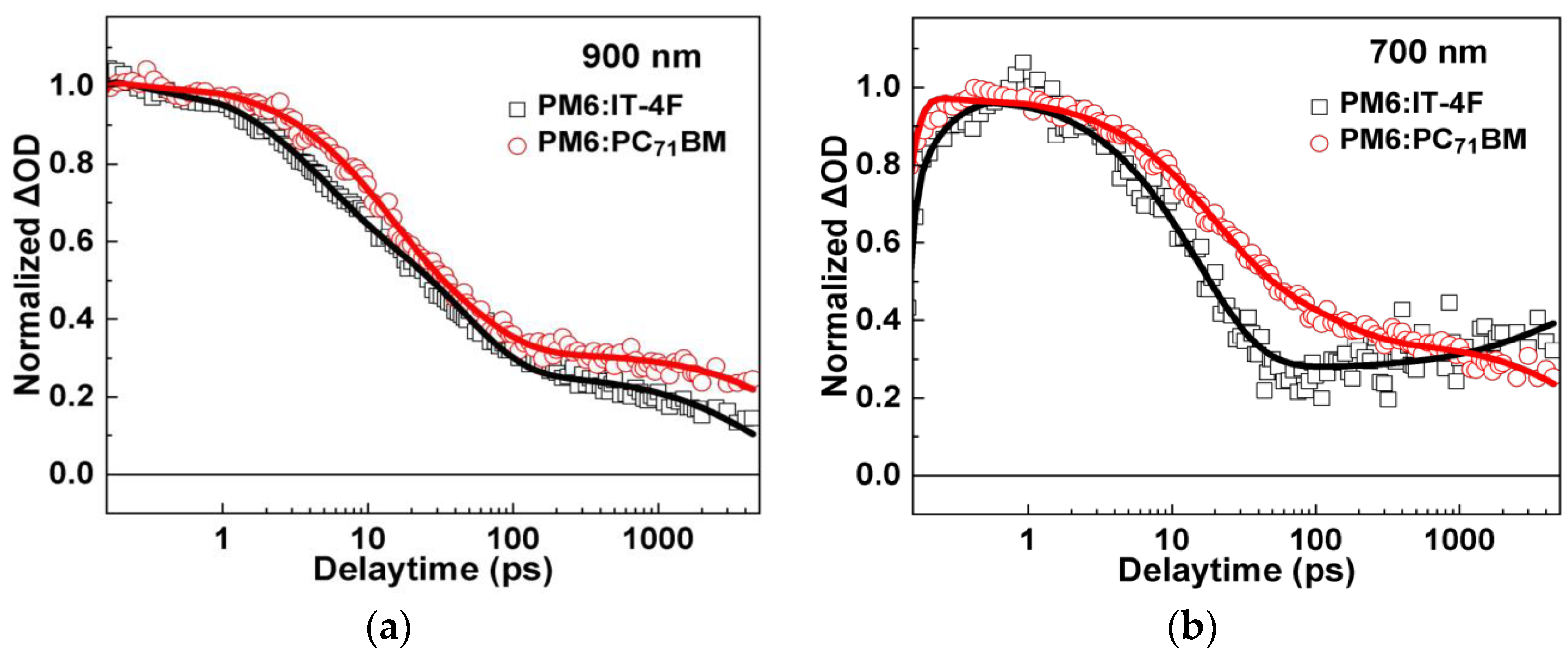
To further understand the evolution of transient species, transient absorption kinetics of PM6:IT−4F and PM6:PC71BM at 900 nm and 700 nm were comparatively analyzed, as shown in Figure 6 and Table 2. It is clearly demonstrated that the decay processes of transient species in PM6:IT−4F and PM6:PC71BM are remarkably different from each other. As for the kinetics of 900 nm (Figure 6a), they can be well-fitted by a tri-exponential decay function. The fast two decay components can be attributed to the dissociation processes of excitons in PM6 phases with different phase sizes, while the slowest decay can be attributed to the decay of localized polarons. We find that the polymer exciton diffusion and dissociation time in PM6:IT−4F is slightly shorter than that in PM6:PC71BM (4.1 ps vs. 10.9 ps), suggesting the size of PM6 phase in PM6:IT−4F active layer is smaller. Furthermore, we analyzed the kinetics of the two active layers at 700 nm (Figure 6b). For PM6:PC71BM, we observed the slowest decay component at the timescale of ~11 ns. Since the lifetime of excitons and charge transfer state are usually <1 ns, the slow decay (~11 ns) can be attributed to the recombination of delocalized polarons. In this work, we observed a slow rise of TA kinetics at 700 nm in PM6:IT−4F. One possible process for this slow rise is the formation of triplet excitons [49]. However, we cannot assign this rise process to the formation of triplet excitons, as the considerations below. First, the energy level of CT state (ECT) in PM6:PC71BM is expected to be higher than that of PM6:IT−4F due to its higher VOC (Figure 2a). Accordingly, we would expect a higher rate of triplet exciton formation due to higher driving force (ECT − ET) for CT recombination [49]. However, we did not observe any signs of triplet formation in the PM6:PC71BM blend film. Additionally, if there is significant triplet generation in PM6:IT−4F but not in PM6:PC71BM solar cells, we usually expect PM6:PC71BM solar cells to have higher PCE. However, in our study, the performance of PM6:IT−4F solar cells is higher, which does not seem to match the significantly higher triplet exciton formation. In stark contrast to the recombination of delocalized polarons in PM6:PC71BM, we observed the formation of delocalized polarons (700 nm) in PM6:IT−4F on the timescale of ~5 ns. Considering the long-time formation processes, we deduce that some of the delocalized polarons originate from the transformation of localized polarons (900 nm), which happens during the transport of polarons. In organic solar cells, the delocalized polaron is usually located in a more orderly region, often with better charge transfer characteristics. Thus, the transformation from localized polarons to delocalized polarons could be beneficial for improving the device’s performance.
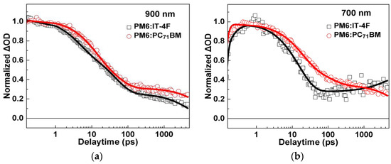
Figure 6.
TA kinetics of PM6:IT−4F and PM6:PC71BM active layers at (a) 900 nm and (b) 700 nm.

Table 2.
Decay time constants (τ) of species in PM6:IT−4F and PM6:PC71BM active layers using multi−exponential curve fitting under the excitation wavelength at 600 nm.
3.5. Electrical Characteristics of Devices
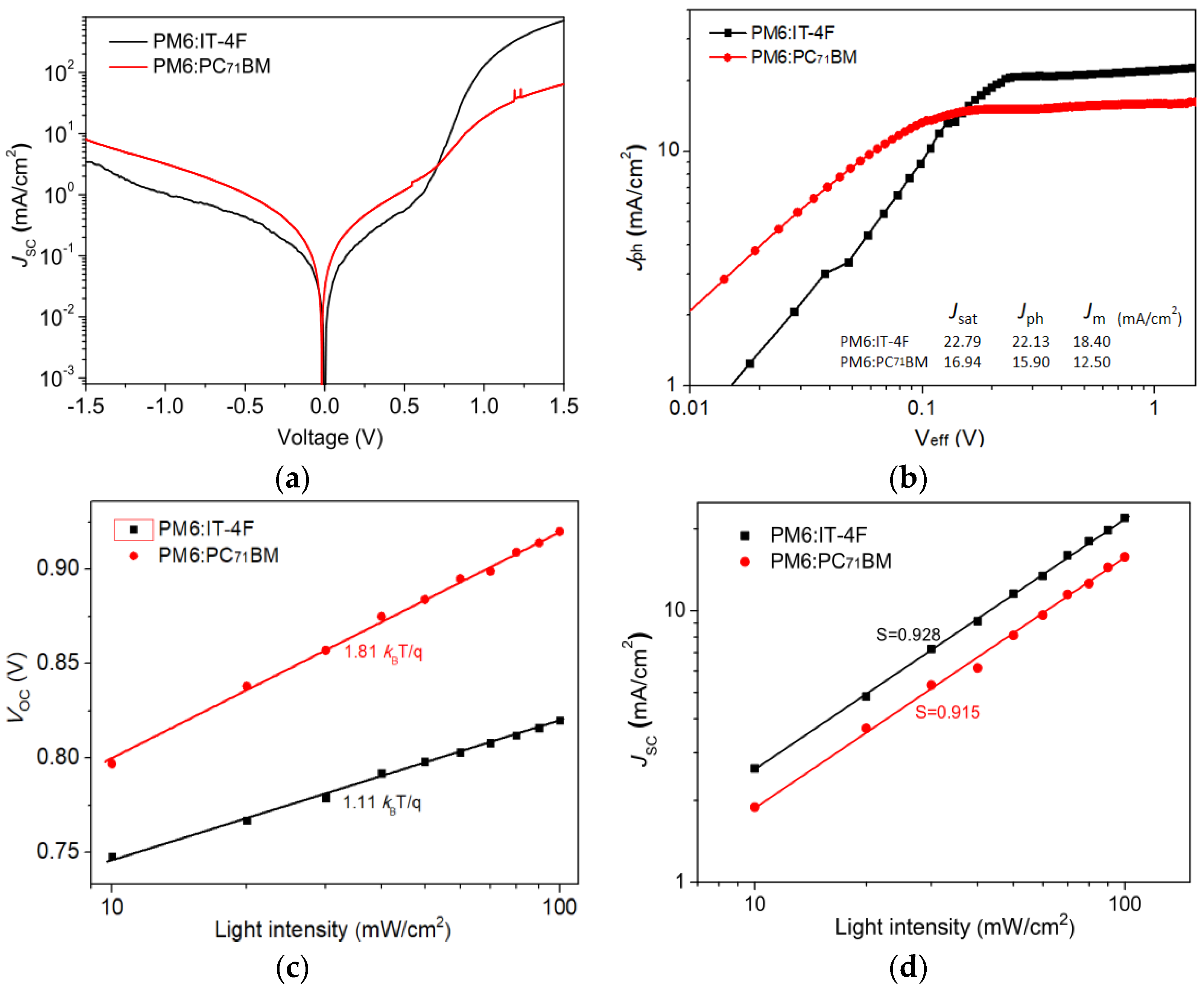
To understand more insights into the dynamic processes of exciton and charge in PM6:IT−4F and PM6:PC71BM devices, the dark current characteristics of the devices were first tested, as shown in Figure 7a. Compared with the PM6:PC71BM device, the PM6:IT−4F device shows a smaller leakage current, and the relative rectification ratio of this non-fullerene-based device is significantly better than that of fullerene-based devices. According to the J−V curves of devices under the dark and light irradiation conditions, the Jph−Veff relationship of the two devices is analyzed in Figure 7b. Jph = JL − JD, JL, and JD are current densities at the conditions of light irradiation and dark. Veff = V0 − V, V is the applied voltage, and V0 is the voltage when Jph = 0 [15]. Herein, we can obtain a current density J (Jsat) at Veff = 2 V, i.e., 22.79 and 16.40 mA/cm2 in PM6:IT−4F and PM6:PC71BM devices, respectively. Meanwhile, we also can acquire a current density (Jm) at the maximum output power condition from Figure 2a. Thus, the exciton dissociation possibility (Pdiss) and charge collection possibility (Pcoll) can be calculated by Jph/Jsat and Jm/Jsat for two devices; thereby, the Pdiss and Pcoll are determined as 97.1% and 80.7%, 96.9%, and 76.2% for PM6:IT−4F and PM6:PC71BM devices, respectively. These results indicate that the PM6:IT−4F device has a higher charge collection capacity than the PM6:PC71BM device. On the other hand, to further investigate the charge recombination mechanism of devices, the VOC versus light intensity curves (log(Plight)) were measured, as shown in Figure 7c. It can be found the slopes of VOC−log(Plight) curves are 1.11kBT/q and 1.81kBT/q for PM6:IT−4F and PM6:PC71BM devices. Usually, the slope of the VOC−log(Plight) is closer to 2kBT/q, the greater the charge defect recombination in the device. Obviously, this slope in PM6:IT−4F is less than the PM6:PC71BM device. It implies that the former device has a smaller charge defect state recombination. Figure 7d shows the relationship between JSC versus light intensity; the slopes of log(JSC)−log(Plight) are fitted as 0.928 and 0.915 for PM6:IT−4F and PM6:PC71BM devices. In general, the slope of log(JSC)−log(Plight) is closer to 1, the lower probability of bimolecular recombination in OSCs. The greater slope of log(JSC)−log(Plight) in the PM6:IT−4F device suggest it has lower bimolecular recombination than PM6:PC71BM devices.
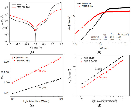
Figure 7.
(a) Dark J−V curves of two OSCs. (b) Jph−Veff of two OSCs. (c) VOC versus light intensity of two OSCs. (d) JSC versus light intensity of two OSCs.
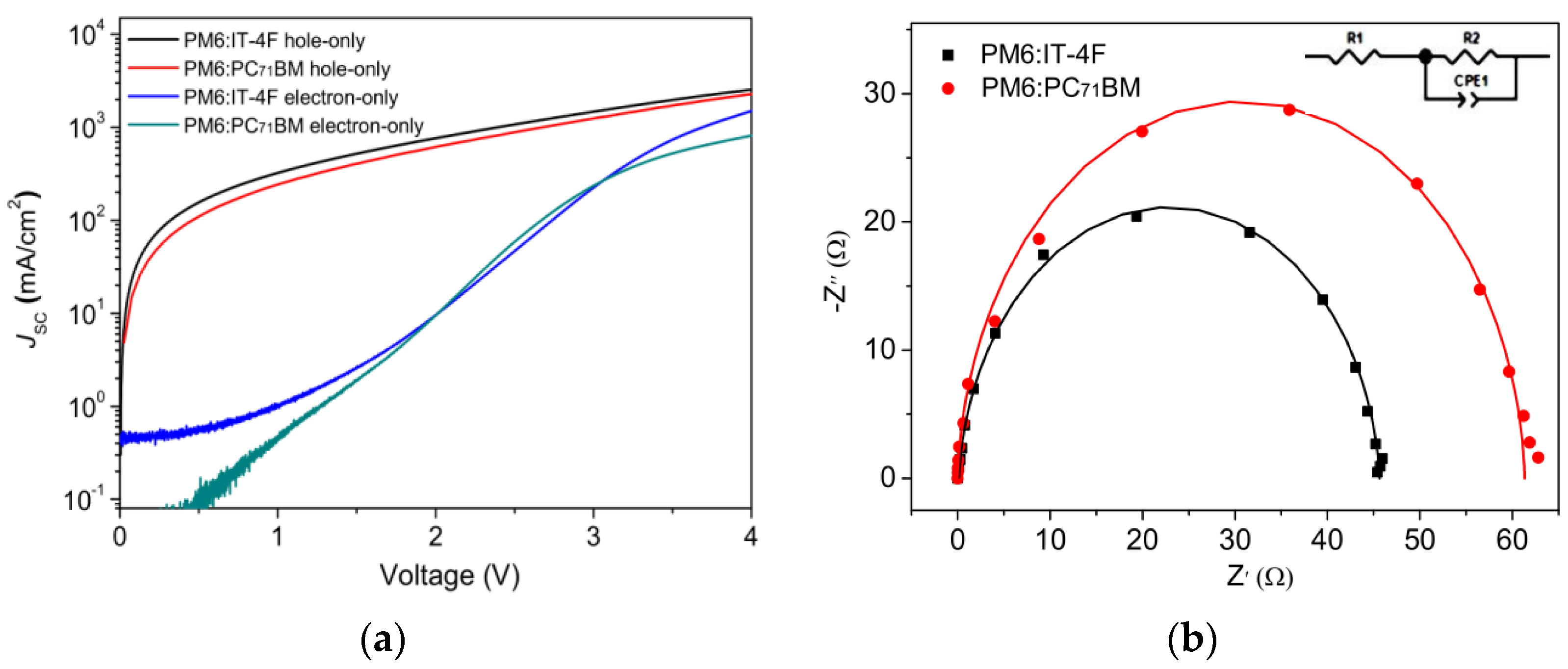
To compare the charge transport characteristics in two devices, the space charge limited current (SCLC) method was carried out, as shown in Figure 8a. The charge mobility can be calculated by the formula below [50].
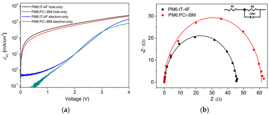
Figure 8.
(a) J−V curves of hole-only and electron−only devices based on the configurations of ITO/MoO3/active layer/MoO3/Ag and ITO/ZnO/active layer/PFN/Ag. (b) EIS spectra curves of two OSCs.
J, ε0, εr, μ, V, and L are current density, vacuum dielectric constant (8.85 × 10⁻¹⁴ F/cm), the relative dielectric constant of polymer (εr = 3), charge mobility, bias voltage, and thickness, respectively. By calculation, the hole mobilities of PM6:IT−4F and PM6:PC71BM devices are determined as 5.4 × 10⁻⁴ and 4.9 × 10⁻⁴ cm2·V−1·s−1. Similarly, the electron mobility values of corresponding devices are 3.2 × 10⁻⁴ and 1.7 × 10⁻⁴ cm2·V−1·s−1. Thus, the µh/µe values can be determined as 1.69 and 2.88. Hence, high charge mobility and good charge transport balance are shown in the PM6:IT−4F device. Figure 8b shows the EIS measurements of two devices. An equivalent circuit (inset picture in Figure 8b) was used to fit the EIS spectra. By fitting the charge–transfer resistance, R2 values are determined as 45.5 Ω and 61.3 Ω. This indicates that better Ohmic contact is formed between the PM6:IT−4F active layer and the electrode, leading to better charge collection, which supports the aforementioned results.
4. Conclusions
In this work, we have fabricated the OSCs based on PM6:IT−4F and PM6:PC71BM active layers and obtained the PCE of 12.82% and 8.78%. Meanwhile, the PCE decay of the PM6:IT−4F device was slower than the PM6:PC71BM device. The efficiency difference between the two OSCs was due to the different photoelectric conversion processes that were determined by the acceptor material and microstructure of the active layer. Compared with the PC71BM acceptor, IT−4F had stronger absorption in the near-infrared region, leading to enhanced photon harvesting in the long wavelength range and markedly increased JSC. Moreover, the PM6:IT−4F active layer had more refined phase scales and D/A phase separation degree, allowing the photogenerated exciton to quickly diffuse to the D/A phase interface for exciton dissociation and energy transfer. Additionally, we also found that some of the delocalized polarons originate from the transformation of localized polarons in the PM6:IT−4F active layer after a long delay. Electrical analysis indicated that lower bimolecular recombination, higher charge transport, and charge collection ability were shown in the PM6:IT−4F device compared with the PM6:PC71BM device. Therefore, the high JSC, FF, PCE, and stability were achieved in PM6:IT−4F solar cells.
Author Contributions
Conceptualization, R.H. and W.Z.; methodology, R.H. and Y.L.; software, R.H. and L.Z.; validation, L.Z. and R.H.; formal analysis, Z.C. and R.H.; investigation, G.W. and R.H.; resources, W.Z. and R.H.; data curation, R.H., Z.C. and G.W; writing—original draft preparation, R.H.; writing—review and editing, R.H. and W.Z.; visualization, R.H. and Y.L.; supervision, W.Z. and R.H.; project administration, R.H.; funding acquisition, W.Z., R.H. and Y.L. All authors have read and agreed to the published version of the manuscript.
Funding
This work was funded by National Natural Science Foundation of China (21903017), Major Cultivation Project of Chongqing University of Arts and Sciences (P2020CL01), the Genera Program of Chongqing Natural Science Foundation (CSTB2022NSCQ−MSX0309, CSTB2022NSCQ−MSX0545), the Science and Technology Research Program of the Chongqing Municipal Education Commission (KJQN202001323, KJZD−K202201303), the General Program of Yongchuan Natural Science Foundation (2022yc−jckx20017), Guangdong Basic and Applied Basic Research Foundation (2023A1515011500), and Scientific Research Projects of Guangzhou University (ZH2023005).
Institutional Review Board Statement
Not applicable.
Informed Consent Statement
Not applicable.
Data Availability Statement
Not applicable.
Acknowledgments
The authors acknowledge the funding support from the National Natural Science Foundation of China, Chongqing Science and Technology Bureau, Chongqing Municipal Education Commission, Yongchuan Science and Technology Bureau, Department of Science and Technology of Guangdong Province, and Guangzhou University.
Conflicts of Interest
The authors declare no conflict of interest.
References
- Oh, J.Y.; Shin, M.; Lee, T.; Jang, W.S.; Lee, Y.J.; Kim, C.S.; Kang, J.W.; Myoung, J.M.; Baik, H.K.; Jeong, U. Highly Bendable Large-area Printed Bulk Heterojunction Film Prepared by the Self-seeded Growth of Poly(3-hexylthiophene) Nanofibrils. Macromolecules 2013, 46, 3534–3543. [Google Scholar] [CrossRef]
- Gu, X.; Zhou, Y.; Gu, K.; Kurosawa, T.; Guo, Y.; Li, Y.; Lin, H.; Schroeder, B.C.; Yan, H.; Molina-Lopez, F.; et al. Roll-to-Roll Printed Large-area All-Polymer Solar Cells with 5% Efficiency Based on a Low Crystallinity Conjugated Polymer Blend. Adv. Energy Mater. 2017, 7, 1602742. [Google Scholar] [CrossRef]
- Zhang, T.; An, C.; Xu, Y.; Bi, P.; Chen, Z.; Wang, J.; Yang, N.; Yang, Y.; Xu, B.; Yao, H.; et al. A Medium-Bandgap Nonfullerene Acceptor Enabling Organic Photovoltaic Cells with 30% Efficiency under Indoor Artificial Light. Adv. Mater. 2022, 34, 2207009. [Google Scholar] [CrossRef]
- Krebs, F.C. Roll−to−Roll Fabrication of Monolithic Large−area Polymer Solar Cells Free from Indium-Tin-Oxide. Sol. Energy Mater. Sol. Cells 2009, 93, 1636–1641. [Google Scholar] [CrossRef]
- Thirugnanasambandam, M.; Iniyan, S.; Goic, R. A Review of Solar Thermal Technologies. Renew. Sust. Energy Rev. 2010, 14, 312–322. [Google Scholar] [CrossRef]
- Cook, T.R.; Dogutan, D.K.; Reece, S.Y.; Surendranath, Y.; Nocera, D.G. Solar Energy Supply and Storage for the Legacy and Non-legacy Worlds. Chem. Rev. 2010, 110, 6474–6502. [Google Scholar] [CrossRef]
- Zhang, T.; An, C.; Bi, P.; Lv, Q.; Qin, J.; Hong, L.; Cui, Y.; Zhang, S.; Hou, J. A Thiadiazole-Based Conjugated Polymer with Ultradeep HOMO Level and Strong Electroluminescence Enables 18.6% Efficiency in Organic Solar Cell. Adv. Energy Mater. 2021, 11, 2101705. [Google Scholar] [CrossRef]
- Zheng, Z.; Wang, J.; Bi, P.; Ren, J.; Wang, Y.; Yang, Y.; Liu, X.; Zhang, S.; Hou, J. Tandem Organic Solar Cell with 20.2% Efficiency. Joule 2022, 6, 171–184. [Google Scholar] [CrossRef]
- Zhang, T.; An, C.; Lv, Q.; Qin, J.; Cui, Y.; Zheng, Z.; Xu, B.; Zhang, S.; Zhang, J.; He, C.; et al. Optimizing Polymer Aggregation and Blend Morphology for Boosting the Photovoltaic Performance of Polymer Solar Cells via a Random Terpolymerization Strategy. J Energy Chem. 2021, 59, 30–37. [Google Scholar] [CrossRef]
- An, C.; Qin, Y.; Zhang, T.; Lv, Q.; Qin, J.; Zhang, S.; He, C.; Ade, H.; Hou, J. Optimization of Active Layer Morphology by Small-Molecule Donor Design Enables Over 15% Efficiency in Small-Molecule Organic Solar Cells. J Mater. Chem. A 2021, 9, 13653–13660. [Google Scholar] [CrossRef]
- Kumar, S.; Panigrahi, D.; Dhar, A. Efficiency Enhancement of ZnO Based Inverted BHJ Solar Cells via Interface Engineering using C70 Modifier. Org. Electron. 2016, 38, 1–7. [Google Scholar] [CrossRef]
- Heo, S.W.; Song, K.W.; Choi, M.H.; Sung, T.H.; Moon, D.K. Patternable Solution Process for Fabrication of Flexible Polymer Solar Cells using PDMS. Sol. Energy. Mater. Sol. Cells 2011, 95, 3564–3572. [Google Scholar] [CrossRef]
- An, Q.; Wang, J.; Gao, W.; Ma, X.; Hu, Z.; Gao, J.; Xu, C.; Hao, M.; Zhang, X.; Yang, C.; et al. Alloy−like Ternary Polymer Solar Cells with Over 17.2% Efficiency. Sci. Bull. 2020, 65, 538–545. [Google Scholar] [CrossRef] [PubMed]
- Ma, X.; Wang, J.; Gao, J.; Hu, Z.; Xu, C.; Zhang, X.; Zhang, F. Achieving 17.4% Efficiency of Ternary Organic Photovoltaics with Two Well-Compatible Nonfullerene Acceptors for Minimizing Energy Loss. Adv. Energy Mater. 2020, 10, 2001404. [Google Scholar] [CrossRef]
- Xu, W.; Ma, X.; Son, J.H.; Jeong, S.Y.; Niu, L.; Xu, C.; Zhang, S.; Zhou, Z.; Gao, J.; Woo, H.Y.; et al. Smart Ternary Strategy in Promoting the Performance of Polymer Solar Cells Based on Bulk-Heterojunction or Layer-By-Layer Structure. Small 2022, 18, 2104215. [Google Scholar] [CrossRef]
- Zhou, H.; Zhang, L.; Ma, X.; Xibei, Y.; Zheng, Y.; Liu, Z.; Gao, X.; Zhang, J.; Liu, Z.; Zhang, F. Approaching 18% Efficiency of Ternary Layer-by-Layer Polymer Solar Cells with Alloyed Acceptors. Chem. Eng. J 2023, 462, 142327. [Google Scholar] [CrossRef]
- Afzal, A.M.; Bae, I.G.; Aggarwal, Y.; Park, J.; Jeong, H.R.; Choi, E.H.; Park, B. Highly Efficient Self−powered Perovskite Photodiode with an Electron−blocking Hole−transport NiOx Layer. Sci. Rep. 2021, 11, 169. [Google Scholar] [CrossRef]
- Lee, H.-J.; Na, S.-I. Investigation of PCBM/ZnO and C60/BCP-based Electron Transport Layer for High-performance p-i-n Perovskite Solar Cells. J. Alloys Compd. 2022, 921, 166007. [Google Scholar] [CrossRef]
- An, C.; Zheng, Z.; Hou, J. Recent Progress in Wide Bandgap Conjugated Polymer Donors for High-performance Nonfullerene Organic Photovoltaics. Chem. Commun. 2020, 56, 4750–4760. [Google Scholar] [CrossRef]
- Ma, X.; Zeng, A.; Gao, J.; Hu, Z.; Xu, C.; Son, J.H.; Jeong, S.Y.; Zhang, C.; Li, M.; Wang, K.; et al. Approaching 18% Efficiency of Ternary Organic Photovoltaics with Wide Bandgap Polymer Donor and Well Compatible Y6:Y6−10 as Acceptor. Natl. Sci. Rev. 2021, 8, 15–24. [Google Scholar] [CrossRef]
- Cha, H.; Zheng, Y.; Dong, Y.; Lee, H.H.; Wu, J.; Bristow, H.; Zhang, J.; Lee, H.K.H.; Tsoi, W.C.; Bakulin, A.A.; et al. Exciton and Charge Carrier Dynamics in Highly Crystalline PTQ10:IDIC Organic Solar Cells. Adv. Energy Mater. 2020, 10, 2001149. [Google Scholar] [CrossRef]
- Xu, W.; Zhu, X.; Ma, X.; Zhou, H.; Li, X.; Jeong, S.Y.; Woo, H.Y.; Zhou, Z.; Sun, Q.; Zhang, F. Achieving 15.81% and 15.29% Efficiency of All-Polymer Solar Cells Based on Layer−by−Layer and Bulk Heterojunction structures. J. Mater. Chem. A 2022, 10, 13492–13499. [Google Scholar] [CrossRef]
- Chen, X.; Wang, D.; Wang, Z.; Li, Y.; Zhu, H.; Lu, X.; Chen, W.; Qiu, H.; Zhang, Q. 18.02% Efficiency Ternary Organic Solar Cells with a Small-Molecular Donor Third Component. Chem. Eng. J. 2021, 424, 130397. [Google Scholar] [CrossRef]
- Song, J.; Zhu, L.; Li, C.; Xu, J.; Wu, H.; Zhang, X.; Zhang, Y.; Tang, Z.; Liu, F.; Sun, Y. High−Efficiency Organic Solar Cells with Low Voltage Loss Induced by Solvent Additive Strategy. Matter 2021, 4, 2542–2552. [Google Scholar] [CrossRef]
- Zhao, L.; Ji, H.; Li, S.; Shi, Q.; Zhu, C.; Wang, W.; Huang, D. The Charge Dynamics of PBDB-TF:IT−4F Based Non-fullerene Organic Solar Cells with 1,8-diiodooctane Additive. Appl. Surf. Sci. 2021, 569, 151120. [Google Scholar] [CrossRef]
- Günes, S.; Neugebauer, H.; Sariciftci, N.S. Conjugated Polymer−Based Organic Solar Cells. Chem. Rev. 2007, 107, 1324–1388. [Google Scholar] [CrossRef]
- Coropceanu, V.; Cornil, J.; Silva, D.A.; Olivier, Y.; Silbey, R.; Bredas, J.L. Charge Transport in Organic Semiconductors. Chem. Rev. 2007, 107, 926. [Google Scholar] [CrossRef]
- Sariciftci, N.; Smilowitz, L.; Heeger, A.; Wudl, F. Photoinduced Electron Transfer from a Conducting Polymer to Buckminsterfullerene. Science 1992, 258, 1474–1476. [Google Scholar] [CrossRef]
- Sun, S.; Salim, T.; Mathews, N.; Duchamp, M.; Boothroyd, C.; Xing, G.; Sumbce, T.; Lam, Y. The Origin of High Efficiency in Low-Temperature Solution-Processable Bilayer Organometal Halide Hybrid Solar Cells. Energ. Environ. Sci. 2014, 7, 399–407. [Google Scholar] [CrossRef]
- Hu, R.; Liu, Y.; Cheng, J.; Chen, Y.; Zhang, W.; Liu, H. Effect of [6,6-phenyl C61- butyric Acid Methyl Ester Phase on the Charge Generation of Poly(3- hexylthiophene)-based Polymer Solar Cells. J. Power Sources 2018, 390, 87–92. [Google Scholar] [CrossRef]
- Zhu, X.; Guo, B.; Fang, J.; Zhai, T.; Wang, Y.; Li, G.; Zhang, J.; Wei, Z.; Duhm, S.; Guo, X.; et al. Surface Modification of ZnO Electron Transport Layers with Glycine for Efficient Inverted Non-fullerene Polymer Solar Cells. Org. Electron. 2019, 70, 25–31. [Google Scholar] [CrossRef]
- Jasiunas, R.; Zhang, H.; Devizis, A.; Franckevicius, M.; Gao, F.; Gulbinas, V. Thermally Activated Reverse Electron Transfer Limits Carrier Generation Efficiency in PM6:Y6 Non-Fullerene Organic Solar Cells. Solar RRL 2022, 6, 2100963. [Google Scholar] [CrossRef]
- Xu, X.; Jing, W.; Meng, H.; Guo, Y.; Yu, L.; Li, R.; Peng, Q. Sequential Deposition of Multicomponent Bulk Heterojunctions Increases Efficiency of Organic Solar Cells. Adv. Mater. 2023, 35, 2208997. [Google Scholar] [CrossRef] [PubMed]
- Zhang, M.; Guo, X.; Ma, W.; Ade, H.; Hou, J. A Large-Bandgap Conjugated Polymer for Versatile Photovoltaic Applications with High Performance. Adv. Mater. 2015, 27, 4655–4660. [Google Scholar] [CrossRef]
- Zhang, K.N.; Jiang, Z.N.; Wang, T.; Qiao, J.W.; Feng, L.; Qin, C.C.; Yin, H.; So, S.K.; Hao, X.T. Exploring the Mechanisms of Exciton Diffusion Improvement in Ternary Polymer Solar Cells: From Ultrafast to Ultraslow Temporal Scale. Nano Energy 2021, 79, 105513. [Google Scholar] [CrossRef]
- Liu, P.; Wang, W.; Liu, S.; Yang, H.; Shao, Z. Fundamental Understanding of Photocurrent Hysteresis in Perovskite Solar Cells. Adv. Energy Mater. 2019, 9, 1803017. [Google Scholar] [CrossRef]
- Li, Z.; Xu, X.; Zhang, W.; Meng, X.; Genene, Z.; Ma, W.; Mammo, W.; Yartsev, A.; Andersson, M.R.; Janssen, R.A.J.; et al. 9.0% Power Conversion Efficiency from Ternary All-Polymer Solar Cells. Energy Environ. Sci. 2017, 10, 2212–2221. [Google Scholar] [CrossRef]
- Liu, S.; Chen, D.; Hu, X.; Xing, Z.; Wan, J.; Zhang, L.; Tan, L.; Zhou, W.; Chen, Y. PrinTableand Large-Area Organic Solar Cells Enabled by a Ternary Pseudo-Planar Heterojunction Strategy. Adv. Funct. Mater. 2020, 30, 2003223. [Google Scholar] [CrossRef]
- Jiang, W.; Yu, R.; Liu, Z.; Peng, R.; Mi, D.; Hong, L.; Wei, Q.; Hou, J.; Kuang, Y.; Ge, Z. Ternary Nonfullerene Polymer Solar Cells with 12.16% Efficiency by Introducing One Acceptor with Cascading Energy Level and Complementary Absorption. Adv. Mater. 2018, 30, 1703005. [Google Scholar] [CrossRef]
- Ge, Y.; Hu, L.; Zhang, L.; Fu, Q.; Xu, G.; Xing, Z.; Huang, L.; Zhou, W.; Chen, Y. Polyolefin Elastomer as the Anode Interfacial Layer for Improved Mechanical and Air Stabilities in Nonfullerene Solar Cells. ACS Appl. Mater. Interfaces 2020, 12, 10706–10716. [Google Scholar] [CrossRef]
- Zhou, L.; Zhang, J.; Zhu, C.; Qin, S.; Angunawela, I.; Wan, Y.; Ade, H.; Li, Y. Introducing Low-Cost Pyrazine Unit into Terpolymer Enables High-Performance Polymer Solar Cells with Efficiency of 18.23%. Adv. Funct. Mater. 2022, 32, 2109271. [Google Scholar] [CrossRef]
- Zhang, F.; Inganäs, O.; Zhou, Y.; Vandewal, K. Development of Polymer-Fullerene Solar Cells. Natl. Sci. Rev. 2016, 3, 222–239. [Google Scholar] [CrossRef]
- Xu, W.; Zhang, M.; Ma, X.; Zhu, X.; Jeong, S.Y.; Woo, H.Y.; Zhang, J.; Du, W.; Wang, J.; Liu, X.; et al. Over 17.4% Efficiency of Layer-by-Layer All-Polymer Solar Cells by Improving Exciton Utilization in Acceptor Layer. Adv. Funct. Mater. 2023, 33, 2215204. [Google Scholar] [CrossRef]
- Matsuzaki, H.; Furube, A.; Katoh, R.; Singh, S.P.; Sonar, P.; Williams, E.L.; Vijila, C.; Subramanian, G.S.; Gorelik, S.; Hobley, J. Excited-State Dynamics in Diketopyrrolopyrrole-based Copolymer for Organic Photovoltaics Investigated by Transient Optical Spectroscopy. Jpn. J. Appl. Phys. 2014, 53, 01AB11. [Google Scholar] [CrossRef]
- Marsh, R.A.; Hodgkiss, J.M.; Albert-Seifried, S.; Friend, R.H. Effect of Annealing on P3HT:PCBM Charge Transfer and Nanoscale Morphology Probed by Ultrafast Spectroscopy. Nano Lett. 2010, 10, 923–930. [Google Scholar] [CrossRef] [PubMed]
- Zhang, W.; Hu, R.; Li, D.; Huo, M.M.; Ai, X.C.; Zhang, J.P. Primary Dynamics of Exciton and Charge Photogeneration in Solvent Vapor Annealed P3HT/PCBM Films. J. Phys. Chem. C 2012, 116, 4298–4310. [Google Scholar] [CrossRef]
- Hu, R.; Liu, Y.; Tian, L.; Zhang, W.; He, X. Influence of Thermal Annealing on the Charge Generation and Transport in PM6-based Nonfullerene Solar Cells. J. Mater. Sci. Mater. Electron. 2021, 32, 22879–22889. [Google Scholar] [CrossRef]
- Clarke, T.M.; Jamieson, F.C.; Durrant, J.R. Transient Absorption Studies of Bimolecular Recombination Dynamics in Polythiophene/Fullerene Blend Films. J. Phys. Chem. C 2009, 113, 20934–20941. [Google Scholar] [CrossRef]
- Lo, C.K.; Gautam, B.R.; Selter, P.; Zheng, Z.; Oosterhout, S.D.; Constantinou, I.; Knitsch, R.; Wolfe, R.M.W.; Yi, X.; Brédas, J.L.; et al. Every Atom Counts: Elucidating the Fundamental Impact of Structural Change in Conjugated Polymers for Organic Photovoltaics. Chem. Mater. 2018, 30, 2995–3009. [Google Scholar] [CrossRef]
- Zheng, Y.; Li, S.; Zheng, D.; Yu, J. Effects of Different Polar Solvents for Solvent Vapor Annealing Treatment on the Performance of Polymer Solar Cells. Org. Electron. 2014, 15, 2647–2653. [Google Scholar] [CrossRef]
Disclaimer/Publisher’s Note: The statements, opinions and data contained in all publications are solely those of the individual author(s) and contributor(s) and not of MDPI and/or the editor(s). MDPI and/or the editor(s) disclaim responsibility for any injury to people or property resulting from any ideas, methods, instructions or products referred to in the content. |
© 2023 by the authors. Licensee MDPI, Basel, Switzerland. This article is an open access article distributed under the terms and conditions of the Creative Commons Attribution (CC BY) license (https://creativecommons.org/licenses/by/4.0/).


