Article

Laser Output Performance and Temporal Quality Enhancement at the J-KAREN-P Petawatt Laser Facility

by
Hiromitsu Kiriyama
1,*,
Yasuhiro Miyasaka
1,
Akira Kon
1,
Mamiko Nishiuchi
1,
Akito Sagisaka
1,
Hajime Sasao
2,
Alexander S. Pirozhkov
1,
Yuji Fukuda
1,
Koichi Ogura
1,
Kotaro Kondo
1,
Nobuhiko Nakanii
1,
Yuji Mashiba
1,
Nicholas P. Dover
1,
Liu Chang
1,
Masaki Kando
1,
Stefan Bock
3,
Tim Ziegler
3,4,
Thomas Püschel
3,4,
Hans-Peter Schlenvoigt
3,
Karl Zeil
3 and
Ulrich Schramm
3,4
add Show full author list remove Hide full author list
1
Kansai Institute for Photon Science (KPSI), National Institutes for Quantum Science and Technology (QST), 8-1-7 Umemidai, Kizugawa 619-0215, Japan
2
Naka Fusion Institute (NFI), National Institutes for Quantum Science and Technology (QST), 801-1 Mukoyama, Naka 311-0193, Japan
3
Helmholtz-Zentrum Dresden-Rossendorf (HZDR), Bautzner Landstraße 400, 01328 Dresden, Germany
4
Institute of Nuclear and Particle Physics, Technische Universität Dresden, Zellescher Weg 19, 01069 Dresden, Germany
*
Author to whom correspondence should be addressed.
Photonics 2023, 10(9), 997; https://doi.org/10.3390/photonics10090997
Submission received: 28 July 2023 / Revised: 28 August 2023 / Accepted: 29 August 2023 / Published: 31 August 2023
(This article belongs to the Special Issue Ultrashort Ultra-Intense (Petawatt) Laser)

Abstract

:
We described the output performance and temporal quality enhancement of the J-KAREN-P petawatt laser facility. After wavefront correction using a deformable mirror, focusing with an f/1.3 off-axis parabolic mirror delivered a peak intensity of 1022 W/cm2 at 0.3 PW power levels. Technologies to improve the temporal contrast were investigated and tested. The origins of pre-pulses generated by post-pulses were identified and the elimination of most pre-pulses by removal of the post-pulses with wedged optics was achieved. A cascaded femtosecond optical parametric amplifier based on the utilization of the idler pulse rather than the signal pulse was developed for the complete elimination of the remaining pre-pulses. The orders of magnitude enhancement of the pedestal before the main pulse were obtained by using a higher surface quality of the convex mirror in the Öffner stretcher. A single plasma mirror was installed in the J-KAREN-P laser beam line for further contrast improvement of three orders of magnitude. The above developments indicate, although it has not been directly measured, the contrast can be as high as approximately 1015 up to 40 ps before the main pulse. We also showed an overview of the digital transformation (DX) of the system, enabling remote and automated operation of the J-KAREN-P laser facility.

1. Introduction

With the invention of chirped-pulse amplification (CPA) technology in 1985 [1], Ti:sapphire laser media in 1986 [2], and Kerr lens mode-locking technique in 1991 [3], ultra-fast femtosecond lasers with very high peak powers of up to 10 petawatt (PW) have been developed, planned, and proposed at a number of laboratories and facilities around the world [4]. The latest advances of Ti:sapphire CPA lasers include, in the United States, the generation of pulses at peak powers 1 PW at a repetition rate of 1 Hz [5], 0.85 PW operating at 3.3 Hz [6], in Korea, 4.2 PW at 0.1 Hz [7], in Germany, 1 PW at 1 Hz [8,9], and 2.5 PW at 1 Hz [10], in China, single-shot broadband pulse energy up to 339 J to achieve potentially 10 PW [11], and 1 PW at 0.1 Hz [12]. In Romania, Extreme Light Infrastructure—Nuclear Physics (ELI-NP) achieved two 10 PW lasers capable of one shot every minute [13]. Furthermore, in the United States of America, Zettawat-Equivalent Ultrashort pulse laser System (ZEUS) accomplished 3 PW at 0.1 Hz [14]. In Czech Republic, the capability of 1 PW at 10 Hz laser has been designed and constructed toward generating petawatt pulses at 10 Hz [15].
There are two other types of laser media for potentially generating peak powers of 10 PW and beyond. One is the neodymium-doped glass (Nd:glass) laser which could support a large beam aperture and produce high pulse energy. In Czech Republic, the capability of 10 PW at one shot every minute using a Nd:glass laser has been designed and is under construction [15]. The other is the optical parametric chirped-pulse amplification (OPCPA) technology [16,17] which could support very broad gain bandwidth and have no parasitic oscillation and no gain narrowing effect. In China and the United States of America, 100 PW-class OPCPA lasers have been designed and are under construction [18,19].
The focal intensity at the target plane is a critical parameter for high-field laser–matter interaction experiments. Wavefront aberrations are the main limitation to the realization of the ideal focus spot. By optimizing the wavefront aberrations with the feedback-controlled deformable mirror, diffraction-limited focusing could be achieved. Therefore, with extremely high laser peak powers of up to 10 PW, high intensities have reached 1022 to 1023 W/cm2 [20,21,22] level, which will exceed 1024 W/cm2 possibly in the near future.
The temporal contrast of the laser (the ratio of the intensity of the main pulse to that of pre-pulse, background noise, and pedestal in different temporal ranges) is also important in experiments, such as in the case of ultra-intense laser with nanometer-thick films of solid density or micrometer-scale cluster particles [8,23,24,25,26]. For example, even if the contrast is 10 orders of magnitude for 1022 to 1023 W/cm2 intensities, the intensity of the pre-pulse, the background noise, and the pedestal that precede the main pulse in time is more than 1012 to 1013 W/cm2, which exceeds the laser ablation threshold (1010 to 1011 W/cm2). This can cause unwanted preformed plasma on the solid target and the main pulse interacts primarily with the pre-plasma on the target surface, preventing direct interaction with the solid density material. Therefore, in many experiments, high temporal contrast is required so that the pre-plasma is not formed. Thus, the temporal contrast is crucial for accessing high-field physics and is now under serious investigation throughout the world [27].
Here, using the PW Ti:sapphire laser (J-KAREN-P) developed at QST as an example, we introduced the high-energy amplification and high spatial quality technologies to obtain ultra-high peak power and high, focused intensity, and the high temporal quality techniques for the interaction of high-intensity main lasers especially with the solid targets.

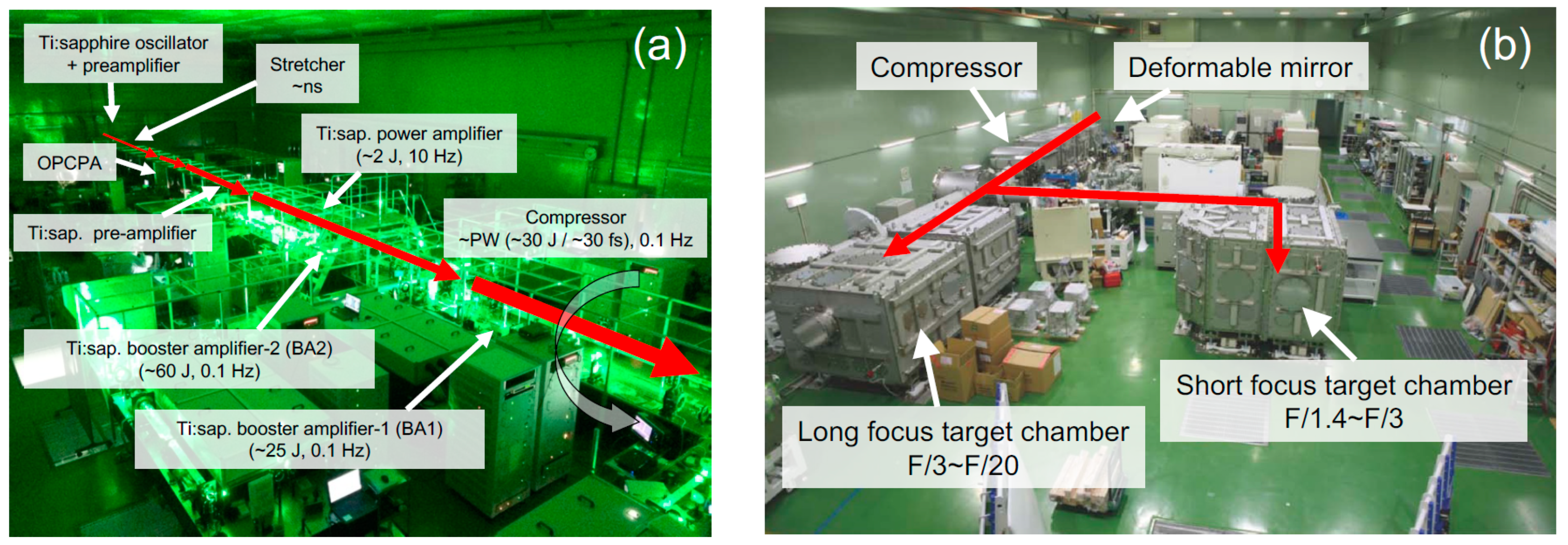
2. Overall J-KAREN-P Laser System Architecture and Output Performance

Figure 1 and Figure 2 show the schematic diagram of the J-KAREN-P laser system, and the view of the J-KAREN-P laser [28,29] and target chambers [30], respectively. The system consists of two CPA stages. The first CPA acts as a high-energy seeder. A pulse duration of approximately 8.5 fs with a repetition rate of 80 MHz and a pulse energy of approximately 6 nJ from a dispersion-compensated Kerr lens mode-locked oscillator is stretched to several picoseconds by the glass block. The stretched pulses are divided by a Pockels cell to a repetition rate of 10 Hz and amplified to approximately 1 mJ by a Ti:sapphire front-end amplifier with a 9-pass configuration. The pump pulses for front-end amplifier is generated by the commercial frequency-doubled Q-switched Nd:YLF laser (Amplitude, Nouvelle-Aquitaine, France, Terra-527-20-M) which can deliver up to 20 mJ at 527 nm with approximately 150 ns pulse duration. Finally, it is recompressed to approximately 25 fs by a pulse compressor consisting of two transmission gratings. An acousto-optic programmable dispersive filter (AOPDF) [31], which can independently control the phase and amplitude of the ultra-short pulse by interaction with acoustic waves shaped in an acousto-optic crystal, is placed in the first CPA stage to obtain Fourier-transform-limited pulses.
The high-energy seed pulse from the first CPA stage is transmitted through the saturable absorber to suppress the background noise of an amplified spontaneous emission (ASE), the pre-pulse, and the pedestal, which are unwanted optical noise associated with the main pulse on the femtosecond time scale, thereby increasing temporal contrast.
In the second CPA stage, the high-contrast laser pulse from the first CPA stage is expanded to a pulse duration of approximately 1.2 ns by an Öffner-type pulse stretcher [32] with aberration-free optics. A second AOPDF is placed after the stretcher to pre-compensate for spectral phase distortions that occur during beam propagation to the pulse compressor.
The ASE, the pre-pulse, and the pedestal are mainly generated in the pre-amplifier stage and amplified together with the main pulse in the subsequent amplifiers. The gain narrowing during amplification results in a narrowing of the spectral bandwidth and should be suppressed to achieve a short pulse after recompression. Therefore, an OPCPA pre-amplifier which provides low optical noise and compensation of the gain narrowing was developed and employed in the laser chain. BBO (β-BaB2O4) nonlinear crystal for the OPCPA was chosen because of its large nonlinear coefficient. When the pump and the seed pulses overlap in the BBO, the energy is directly transferred from the pump pulse to the seed pulse, and the seed pulse is amplified. Therefore, the spectral shape of the amplified seed pulse was determined by the temporal intensity profile of the pump laser. Figure 3a shows an example of how the gain narrowing in the subsequent Ti:sapphire amplifier stages can be compensated by using a pump laser that provides arbitrary temporal profile shaping. The pump laser for OPCPA is custom-built, frequency-doubled, Nd:YAG laser (Amplitude, Nouvelle-Aquitaine, France, Intrepid) at 10 Hz. In this pump laser, the output beam from a continuous wave (CW), single-longitudinal-mode laser diode (LD)-pumped, Yb-doped fiber laser is arbitrarily shaped with the programmable optical pulse shaper and amplified in a rod pre-amplifier, a regenerative amplifier, and two rod main amplifiers, and then frequency doubled in a lithium triborate (LBO) crystal. The programmable optical pulse shaper consists of a Mach–Zehnder modulator, bias control circuit, and a pulse synthesizer. The programmable time step was 125 ps with rise and fall time of 150 ps and the pulse duration can be changed from 1 ns to 4 ns at up to few hundred mJ level. The spectral gain profile of the OPCPA depends on the temporal intensity profile of the pump laser. Therefore, the output spectrum from the OPCPA pre-amplifier can be shaped by controlling the temporal profile of this pump laser.
Figure 3a shows a typical seed pulse spectrum, the output spectrum of the OPCPA for broadband amplification mode, and the spectrum amplified by the final-stage amplifier. A broad spectral bandwidth of approximately 80 nm was obtained by shaping the OPCPA spectrum. The spectral bandwidth of approximately 80 nm was determined by the pulse stretcher design. Since operating the OPCPA in the saturation region causes background noise called parametric fluorescence (PF), which degrades temporal contrast, a high-energy seed pulse of approximately 20 µJ just before the OPCPA was used for low-gain OPCPA operation. Figure 3b shows the OPCPA output energy versus pump energy. The OPCPA output energy was approximately 3 mJ and the gain was 150 when the pump pulse width was approximately 2 ns and the input pump energy was approximately 50 mJ. While amplification gains of 108–1011 have been reported with high-intensity pumping for OPCPA with low energy (approximately nJ) seed pulses, our system, in contrast, had a low gain, which resulted in a low PF, leading to higher temporal contrast.
The output from the OPCPA was up-collimated to a beam diameter of approximately 6 mm by an off-axis beam expander with reflective convex-concave-mirrors [33], and amplified by a Ti:sapphire pre-amplifier. The output from the Ti:sapphire pre-amplifier was then expanded to a diameter of approximately 18 mm with an off-axis beam expander and amplified to approximately 2 J by a Ti:sapphire main amplifier. The pre-amplifier and main amplifier were four-pass amplifiers with 20 mm and 40 mm diameter Ti:sapphire crystals, respectively. The pump laser for Ti:sapphire pre-amplifier was a commercial frequency-doubled Q-switched Nd:YAG laser (Amplitude, Nouvelle-Aquitaine, France, Powerlite DSL 9010) which can deliver up to 1 J at 532 nm with approximately 8 ns (Full Width at Half Maximum: FWHM) pulse duration at 10 Hz. For Ti:sapphire power amplifier, a maximum total pump energy of up to approximately 5 J (532 nm) from five commercially available, frequency-doubled, Q-switched Nd:YAG lasers (MKS Spectra-Physics, Andover, United States, Quanta-Ray Pro-350) with approximately 10 ns (FWHM) operating at a repetition rate of 10 Hz was employed. The power amplifier was pumped by five pump lasers of approximately 5 J, resulting in an average output power of approximately 50 W. The heat generated in the Ti:sapphire crystal was large, and thermal lensing effects were a major problem. Cooling the Ti:sapphire crystal to low temperatures dramatically improved the thermal conductivity and reduced the temperature dependence of the refractive index. By cooling the Ti:sapphire crystal of the main amplifier to low temperatures, the thermal lens focal length was elongated to approximately 4 km, where the thermal lensing effect was almost negligible.
The output from the Ti:sapphire main amplifier was up-collimated to a beam diameter of approximately 50 mm and then approximately 80 mm by off-axis beam expanders with reflective convex-concave mirrors and amplified in a Ti:sapphire booster amplifier-1 (BA1) and a Ti:sapphire booster amplifier-2 (BA2). BA1 and BA2 are three-pass and two-pass geometries using Ti:sapphire crystals with diameters of 80 mm and 120 mm, respectively. In BA1, we used two frequency doubled high-energy Nd:glass lasers at 0.1 Hz (Amplitude, Nouvelle-Aquitaine, France, Constellation II-C). Each glass pump laser can deliver up to 25 J at 527 nm with two pulses (each pulse had approximately 15 ns (FWHM) pulse duration and approximately 12.5 J energy). The two pulses at 1053 nm were frequency-doubled with a single lithium triborate (LBO) crystal. The time interval of these pulses was about 40 ns. In BA2, we used four frequency doubled high-energy Nd:glass lasers at 0.1 Hz (three were from Amplitude, Nouvelle-Aquitaine, France, Constellation II-C, one is from Thales, PARIS, France, ATLAS 25). Each glass pump laser can also deliver ∼25 J at 527 nm with two pulses at 0.1 Hz. Since the gain in the radial direction increased as the aperture of the Ti:sapphire crystal became larger, parasitic oscillations in the radial direction caused by reflections on the crystal side must be suppressed. These oscillations were caused by the formation of resonators due to Fresnel reflections on the crystal side surfaces, which led to a significant reduction in the energy extraction efficiency of the amplifier. To avoid Fresnel reflection at the crystal side surface, we surrounded the crystal side with a liquid having the same refractive index as that of the Ti:sapphire crystal and used a cladding mixed with a dye that absorbed the laser wavelength of the Ti:sapphire crystal. As a result, reflection at the sides of the crystal was eliminated and the seed light causing parasitic oscillation was absorbed by the cladding, thereby successfully suppressing parasitic oscillation.
In BA1, an output energy of approximately 23 J was obtained for an input pump energy of approximately 47 J. The optical-to-optical conversion efficiency was defined as the output energy from the amplifier divided by the pump energy. The extraction efficiency was defined as the output energy minus input energy divided by the pump energy. In BA1, the optical-to-optical and extraction efficiencies were 49% and 45%, respectively. Figure 4a shows the measured output energy as a function of the input pump energy in BA2. The output energy of approximately 63 J was obtained for an input pump energy of approximately 92 J. The conversion efficiency was almost at theoretical limit. In BA2, the optical-to-optical and extraction efficiencies were 68% and 43%, respectively. It seemed that the optical-to-optical efficiency was very high. This was due to the input energy being very high. It was considered a reasonable value in terms of extraction efficiency. The results were evaluated using the Frantz–Nodvik simulation [34] and were in good agreement with the calculations.
The output from the BA2 was sent to a deformable mirror to correct the wavefront distortion and was up-collimated to a beam diameter of approximately 280 mm by two off-axis beam expanders with reflective convex-concave mirrors. The pulse was compressed by a compressor consisting of four diffraction gratings in vacuum and was then sent to the target area. The transmission efficiency of the vacuum beamline from BA2 to the target area, including the pulse compressor, was approximately 60%, and a maximum energy of approximately 35 J can be delivered. The beamline was a vacuum tube, and several mirrors were placed inside the tube to deliver compressed intense laser to the two irradiation vacuum chambers, Experimental area-1 and -2, as shown in Figure 1. The target area was equipped with two chambers, one with short-focusing optics (f/1.3–3) and the other with long-focusing optics (f/10–20). Figure 4b shows the results of pulse duration measurement using the whole beam with a small pulse compressor placed just after BA2. The phase after pulse compression was measured and feedback to the AOPDF was placed after the stretcher for precise phase compensation. The recompressed minimum laser pulse width was 28 fs, and the peak output power after pulse compression was over PW considering the above transmission efficiency. This was an example measured in the shortest pulse duration mode (broadband mode). Although the pulse duration was slightly wider, a pulse with no pedestal can be created by shaping the spectrum like a Gaussian. The theoretical limit amplification and pulse compression like state-of-the-art petawatt-class CPA laser were realized.

3. Spatial Beam Characterization

There are three main causes of laser quality degradation: (1) chromatic aberration, (2) spherical and astigmatic aberrations, and (3) angular dispersion. The chromatic aberration is eliminated by using reflective beam expander optics in the laser system instead of transmissive optics. The spherical aberration and astigmatism are eliminated by introducing a deformable mirror in the laser system, as shown in Figure 1, precisely measuring the wavefront of a large-aperture beam, and feeding the information back to the deformable mirror.
The angular dispersion is removed by precisely adjusting the fourth diffraction grating in the compressor. As a result, a laser beam with an almost perfectly aligned wavefront is realized, and finally, the beam is successfully focused, approaching the theoretical limit [20].
Figure 5a,b shows the measured wavefronts of the J-KAREN-P laser before and after the correction of spherical and astigmatic aberrations by the deformable mirror, and the calculated focusing characteristics predicted from the measurement results. Figure 5c shows the focused spot obtained experimentally by focusing with an off-axis parabolic mirror at f/1.3 after removing aberrations and angular dispersion. A diffraction-limited approximately 1.35 µm (FWHM) was obtained, and an extreme intensity of 1022 W/cm2 was achieved at 0.1 Hz with a J-KAREN-P laser power of 300 TW [20].

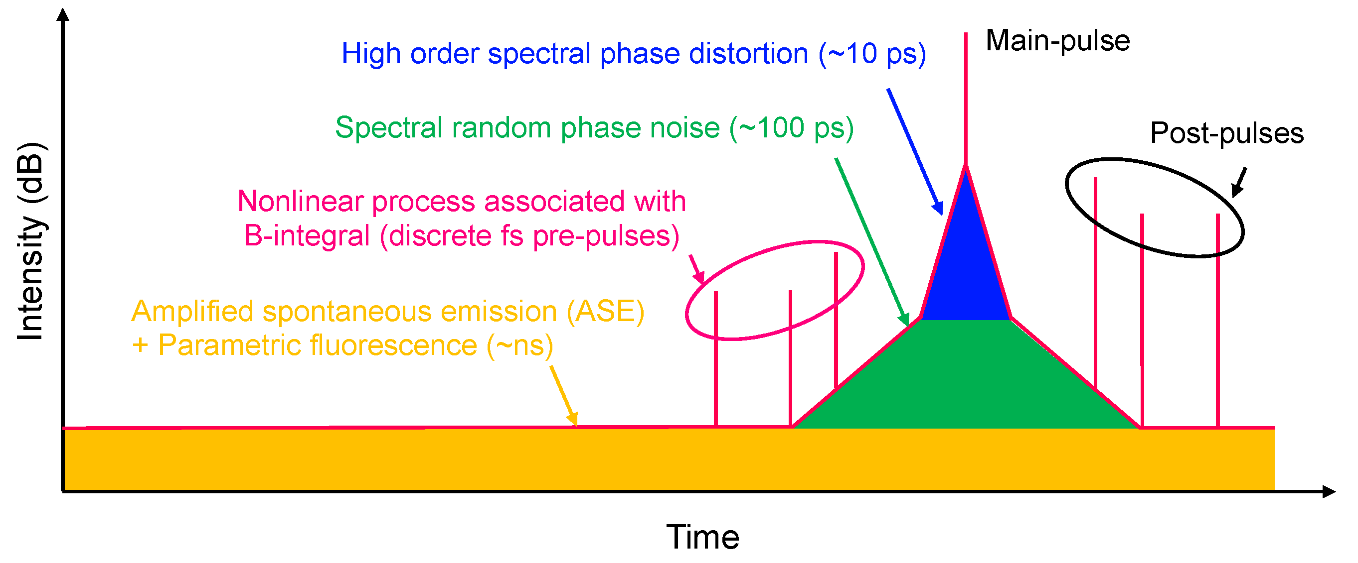
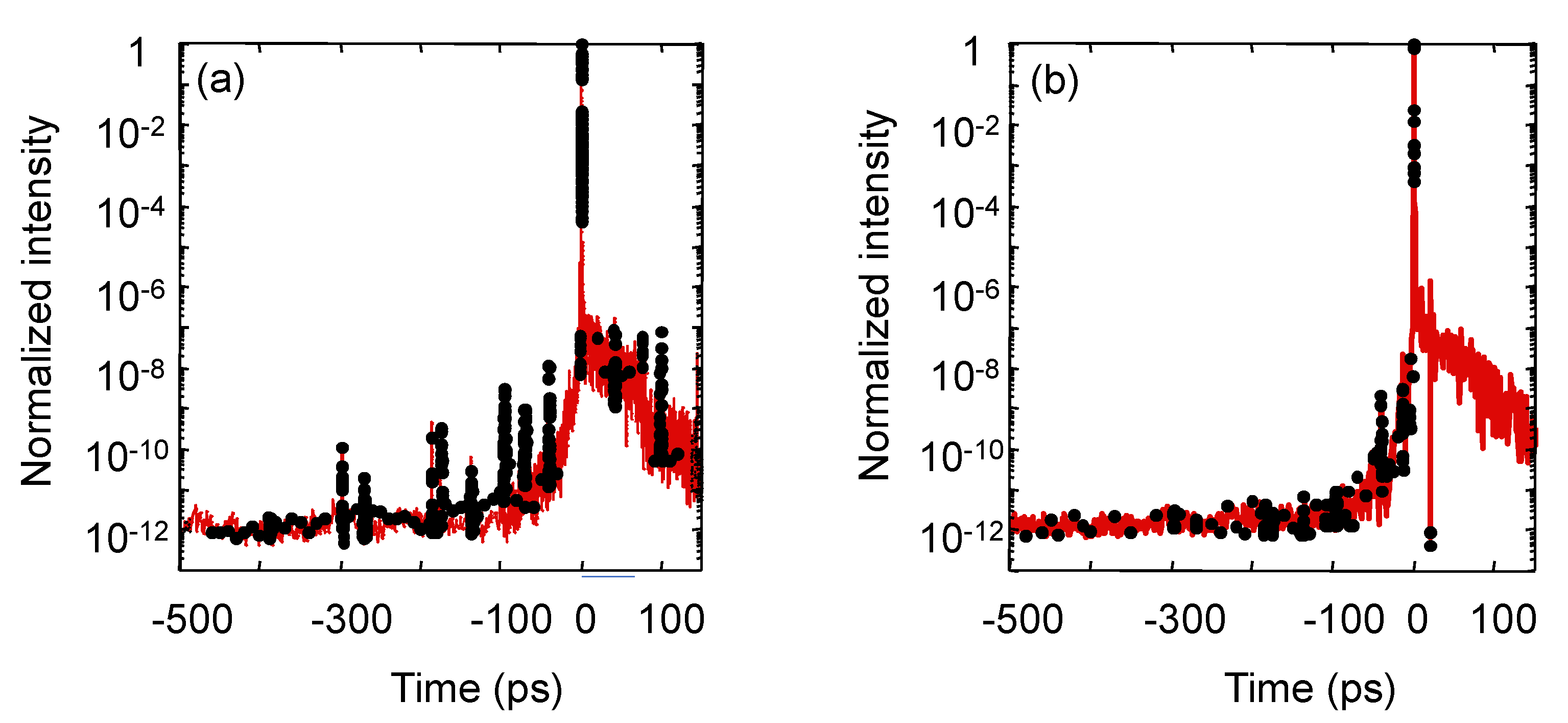
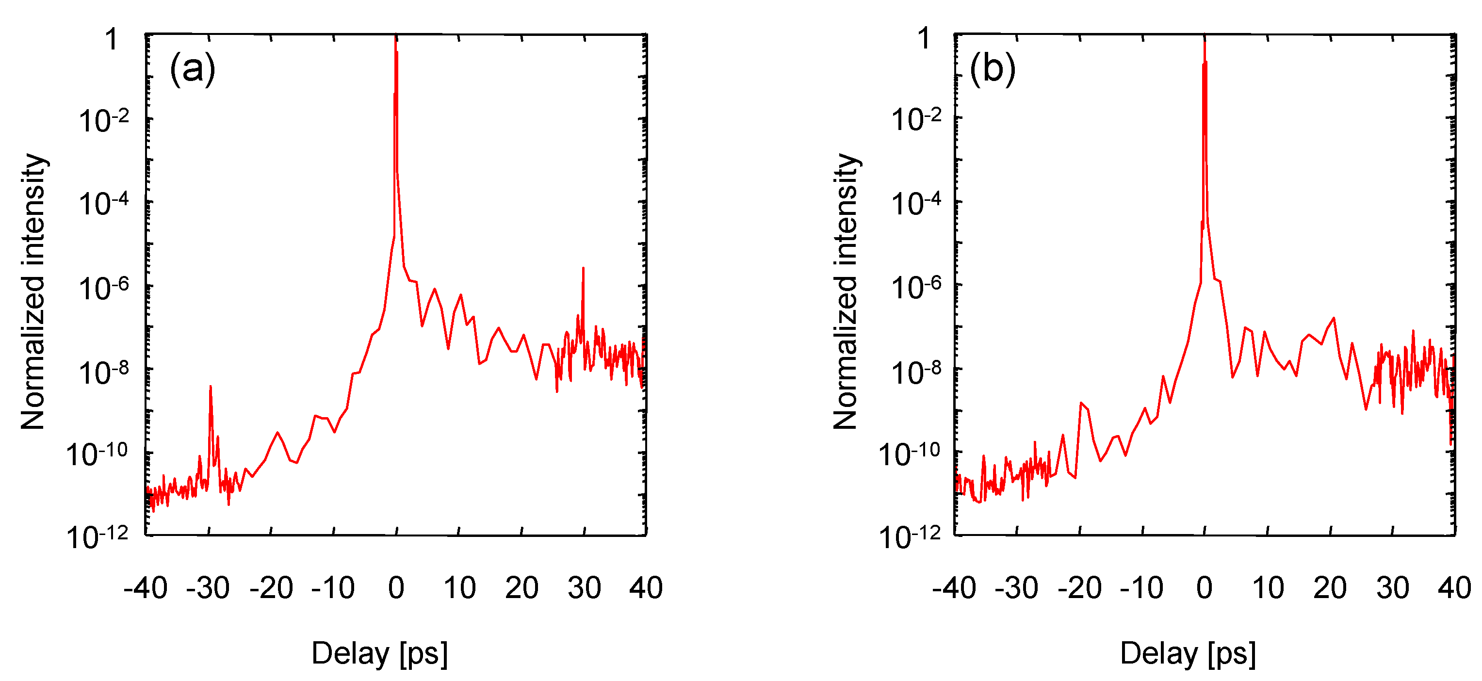
4. Temporal Beam Characterization

Figure 6 shows the typical temporal contrast structure and causes of temporal contrast degradation in CPA lasers. The optical noise, i.e., the causes of temporal contrast degradation, included (1) a few ps pedestal around the main pulse due to higher-order phase distortion, (2) ns background due to ASE or PF, (3) fs pre-pulses generated in a wide time range due to nonlinear coupling [35], (4) tens to hundreds of ps pedestal due to the random spectral phase noise (RSPN) of the main pulse [36,37]. Higher-order phase distortion was minimized using AOPDF as described above. ASE and PF were also minimized by introducing the saturable absorber and operating the OPCPA with low gain [28].

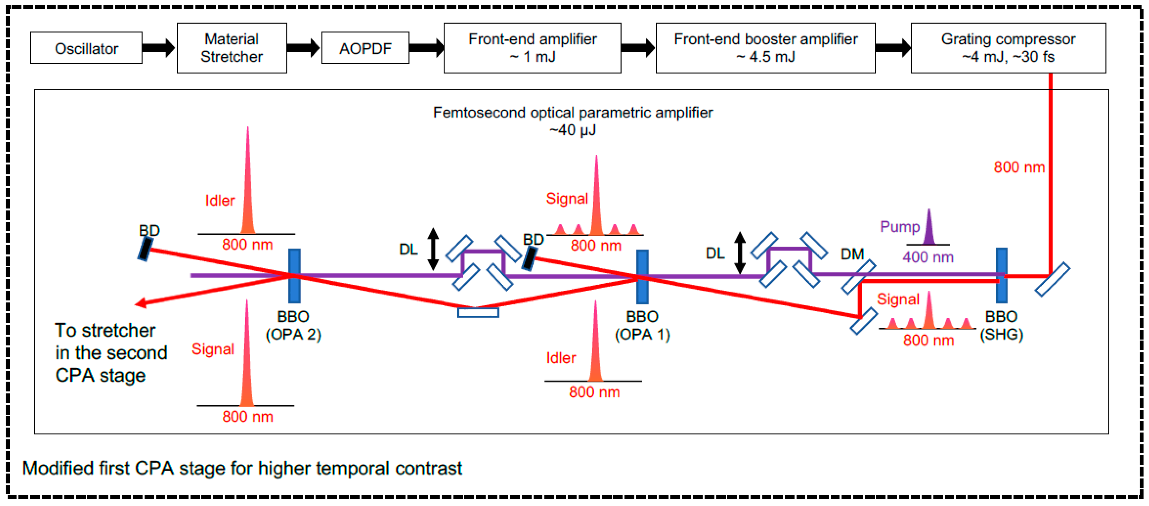
4.1. Femtosecond Pre-Pulse Generated by Post-Pulse in the Second CPA Stage

When the laser passes through a medium with parallel planes, multiple reflections generate post-pulses. If the post-pulse is generated within the duration of the stretched main pulse (~ns), it interferes with the main pulse and modulates the spectral intensity of the main pulse. The modulated spectrum modulates the refractive index in the medium, which modulates the phase of the main pulse. This causes a pre-pulse to be generated after pulse recompression. The intensity of the pre-pulse increases as the B-integral squared, as the phase modulation due to the nonlinear effects increases. The B-integral is a phase modulation based on the change in refractive index proportional to intensity due to the third-order nonlinear susceptibility of the intense laser as it passes through an optical material.
In the J-KAREN-P system, the transmissive optics that cause pre-pulse generation were identified and then replaced with wedged versions to prevent post-pulse generation. The pre-pulses at approximately −270, −175, −137, −96, −64, and −41 ps (Figure 7a) were real. These were coming from the post-pulses due to double reflection in the Ti:sapphire crystals from power amplifier (−270 ps) and pre-amplifiers (−175 ps), the Faraday isolator (−137 ps) between the stretcher and the OPCPA pre-amplifier, the windows (−96 ps) of the cryogenically cooled power amplifier, the windows (−64 ps) of the Pockels cell between the OPCPA and the Ti:sapphire pre-amplifiers and the optics (−41 ps) inside the oscillator, respectively. The two pre-pulses at approximately 298 and 186 ps before the main pulse were artificial pulses originating from the Ti:sapphire crystals of the power amplifier and pre-amplifier, respectively. Figure 7a,b shows the temporal contrast of the J-KAREN-P laser before and after the wedged optics to suppress nonlinear coupling. The Faraday isolator was eliminated from the laser chain to remove the post-pulse because the system provided sufficient optical isolation to avoid the back-reflection light. The temporal contrast was measured using the whole beam with a small compressor in the laser room, and the ASE and PF were achieved to 12 orders of magnitude, which was the detection limit of the instrument, and most of the fs pre-pulses other than the real pre-pulse at approximately −41 ps were successfully removed. The ASE was mainly generated in the pre-amplifier stage and amplified together with the main pulse in the subsequent amplifiers. Thus, the ASE contribution from the last amplifier was considered small. As shown in Figure 7, the ASE contrast did not actually change whether 1 J or 10 J output was used; so, it was not expected to change with 30 J output.

4.2. Picosecond Pedestal Due to the Random Spectral Phase Noise of the Main Pulse (RSPN)

In the stretcher, the laser was spectrally dispersed on optics in a stretcher. Thus, the surface roughness caused the relative phase shift at each wavelength and was directly converted to RSPN. This means that the surface quality of the stretcher optics such as mirror and gratings is important for spectral phase noise, which reduces the temporal contrast of the main pulse and generates a noisy structure on the sides of the main pulse. Therefore, the RSPN was suppressed by replacing the convex mirror with the surface roughness of originally 1 to 2 nm (rms) with that of 0.2 to 0.3 nm (rms). Figure 8 shows the temporal contrast of the J-KAREN-P laser before and after the introduction of the high-quality mirror to suppress RSPN. The improvement of the pedestal contrast by one to two orders of magnitude in the –7 to –33 ps range was clearly observed. The calculation was in good agreement with the experimental data and the high contrast of approximately 12 orders of magnitude was successfully achieved up to approximately 40 ps before the main pulse, as shown in Figure 8.

4.3. Femtosecond Pre-Pulse Generated by Post-Pulse in the First CPA Stage

The final remaining pre-pulse at approximately 41 ps before the main pulse was generated in the commercial oscillator in the first CPA stage and was difficult to eliminate. The technique of the temporal contrast enhancement capability was tested to suppress any pre- and post-pulses generated in the first CPA. The femtosecond optical parametric amplifier (fs-OPA) based on the utilization of the idler pulse rather than the signal pulse was proposed and investigated. The fs-OPA with the idler pulse has been evaluated only for the Nd:glass laser system and there have been only a limited number of reports [38,39,40]. The use of the fs-OPA with the idler pulse in a petawatt-class high-intensity Ti:sapphire laser system has not been studied, to our knowledge.
The schematic diagram of the J-KAREN-P laser system with a more detailed fs-OPA layout is shown in Figure 9. To facilitate the fs-OPA output energy connecting to the J-KAREN-P laser, the output of the existing first CPA was sent to the additional four-pass amplifier (Front-end booster amplifier), which used a Tisapphire crystal placed at the Brewster angle, pumped by a frequency-doubled, Q-switched Nd:YAG laser with a maximum output energy of up to 25 mJ (Amplitude, Nouvelle-Aquitaine, France, Minilite II). In this experiment, the amplified broadband pulse of approximately 4.5 mJ was recompressed to a pulse duration of approximately 35 fs having approximately 4 mJ. The compressed laser pulse was frequency-doubled by a Type I β-BaB2O4 (BBO) crystal to generate a second harmonic pulse with the energy of approximately 1.5 mJ for pumping two OPAs consisting of two BBO crystals with a small wedge angle. The residual and attenuated fundamental pulses are used as the signal pulse for the first OPA. The internal angle of the OPA stage was designed to be 0.06 degrees. The timing between the pump and signal pulses for the first and second OPAs was accurately controlled by the delay stage.
Only the main (signal) pulse was selectively amplified in the first OPA because the pump pulse duration was tens of femtoseconds, so that the pump did not overlap with the pre-pulse at 41 ps before the main pulse and other pre- and post-pulses. In the first OPA, the signal pulse at a frequency of ωs was amplified with a pump pulse at a frequency of ωp. At the same time in first OPA, an isolated idler pulse at a frequency of ωi = ωpωs was created in the parametric mixing process between the pump and the signal pulse, and subsequently sent into second OPA pumped by the identical pump pulse. In second OPA, the signal pulse created by the idler pulse generated in first OPA was shifted back to the original frequency ωs, and all pulses except the main pulse were removed.
Firstly, to determine the effectiveness of the temporal contrast enhancement by use of the fs-OPA, a 3 mm thick uncoated plane-parallel plate was inserted to generate ±30 ps pre- and post-pulses just after the first CPA stage. Figure 10a,b shows the temporal contrast with the saturable absorber and the fs-OPA, respectively. The results demonstrate the fact that the fs-OPA is useful and suitable for eliminating the pre- and post-pulses from the first CPA stage. Figure 11a shows the measured temporal contrast of the J-KAREN-P laser system with approximately 1 and 10 J output pulse energies with the saturable absorber after the existing first CPA. The real pre-pulse came from the post-pulse due to the optics inside the oscillator. By using the fs-OPA, the pre-pulse at −41 ps and the post-pulse at 41 ps were removed, as shown in Figure 11b.

4.4. Residual Pre-Pulses

There were other noise sources. For an exponentially rising pedestal within a few picoseconds of the compressed pulse, the scattering from the diffraction gratings [41] and the RSPN by surface roughness of the concave mirror in the stretcher are the sources of this feature [42,43]. Replacing the grating and concave mirror by higher-quality components would result in an order-of-magnitude reduction in the intensity of the pedestal. The large gratings in the compressor also contribute to such optical noise generation. Although efforts were made to remove as much optical noise as possible in the laser system, it was not easy to remove all the optical noise with the laser system alone and, so, a plasma mirror (PM) was introduced to remove the optical noise that could not be removed.
As shown in Figure 1, experimental area-1 allowed experiments with a high-focused intensity of 1022 W/cm2, and so, a PM was installed for ultra-high temporal contrast [44,45]. A laser pulse was focused and irradiated onto a transparent optical surface with very low reflectivity, for which an antireflection (AR)-coated glass plate was one of the best choices to remove residual pre-pulses to enhance the temporal contrast. The low-intensity pre-pulses, background noise, and pedestal were transmitted through the AR-coated glass plate, while the main pulse was reflected by the high-density plasma created on the optical surface of the PM by the rising edge of the main pulse. Thus, the pre-pulses, the background noise, and the pedestal that could not be removed by the above techniques can be well removed. The PM consisted of two periscope pairs, two off-axis parabolic mirrors with focal length of 2 m (f/8), and a PM substrate. After the compressor, the polarization of the beam was p. The first periscope was used to rotate the polarization of the pulse from p to s to obtain higher reflectivity at the PM substrate. The first off-axis parabolic mirror was employed to focus down to the PM substrate. The second one was for re-collimating the beam size same as the incident beam. The polarization of the beam was again rotated back by the second periscope to the original state (p-polarization). The reflectivity increased as the fluence on the PM substrate increased, reaching 85% at a fluence of approximately 500 kJ/cm2. The recompressed pulse duration was around 45 fs having approximately 10 J in this experiment.
As shown in Figure 12a, a single plasma mirror configuration can improve contrast by three orders of magnitude [30]. However, the current temporal contrast measurement system was limited to approximately 12 orders of magnitude and actual measurements are not possible. Therefore, as shown in this paper, a method was generally used in which the contrast was measured to the level where it could be measured (approximately 12 orders of magnitude), the contrast improvement ratio by the plasma mirror (approximately three orders of magnitude) was measured separately, and the final contrast was evaluated by combining these measurements. The current J-KAREN-P laser pulse was expected to have a high contrast of approximately 15 orders of magnitude up to approximately 40 ps before the main pulse, as shown in Figure 12b.
It was not only simply 12 orders of magnitude baseline in the temporal contrast trace determined by ASE but also new techniques to remove as much pedestal around the main pulse and femtosecond pre-pulse as possible, which are presented in this paper. For example, in China, the temporal contrast of approximately 11–12 orders of magnitude at tens of picoseconds in SULF-1PW facility using single plasma mirror was demonstrated. In Germany, approximately 11–12 orders of magnitude contrast at tens of picoseconds in DRACO-1PW facility using single plasma mirror was also reported. In Korea, in the 4 PW facility, approximately 17 orders of magnitude contrast using double plasma mirror was achieved [30].
We are upgrading the plasma mirror in parallel, and plan to achieve a further approximately three orders of magnitude improvement in contrast over the current single plasma mirror configuration by using a double plasma mirror configuration.

5. Automation Initiative of the J-KAREN-P Laser System

The project was adopted by the Ministry of Education, Culture, Sports, Science and Technology (MEXT) for five years, starting in FY2021 for promoting the public utilization of advanced research infrastructure (Program for Advanced Research Equipment Platforms).
In the laser room, the project will realize a remote control and visualization system for the measurement of laser parameters such as laser profile images, as well as the automatic start-up of the pump laser and the automatic adjustment of the optical path of the main laser. It also performs remote control of laser shielding, attenuation, and triggering.
In the target chamber room, remote measurement of laser energy and laser spectrum and construction of a database of these data will also be performed.
The system will be developed for automatic inspection of large mirror damage and integrated monitoring of laser parameters by AI image analysis. These remoting and visualization systems will maximize the operational efficiency of the laser system for a wide variety of experiments and, at the same time, realize safe laser operations.
For example, we developed the web application shown in Figure 13a, which enables the remote operation of the laser shielding to block the laser and diagnostic to measure the laser parameters, installed at each amplification section. The shielding and measurement status of the laser can be visualized in real time, and the laser operation status can be shared via a wireless LAN. In the case of an emergency, laser emission can be stopped immediately by remote control. As shown in Figure 13b, an automatic laser optical path control system was installed at key locations in the laser system. The laser pointing is constantly monitored, the data are acquired, and mirrors with actuators are automatically controlled to shorten the laser start-up time and ensure a stable supply over a long period.

6. Conclusions

The petawatt J-KAREN-P laser system at QST was constructed with in-house technologies. By optimizing the amplifiers, the efficient operation of the broadband output energies of 63 J at 0.1 Hz and recompression pulse duration of less than 30 fs were demonstrated. According to the precise measurements of the focal spot and encircled energy, 1022 W/cm2 by focusing a wavefront corrected 0.3 PW laser beam by optimizing the deformable mirror with an f/1.3 off-axis parabolic mirror was achieved on target. All of the pre-pulses generated by the post-pulses were eliminated via the use of wedged optical components and fs-OPA. By improving the optical quality of the convex mirror in the Öffner stretcher, orders of magnitude enhancement of picosecond coherent pedestal were demonstrated. We integrated the single plasma mirror into the J-KAREN-P, achieving contrast enhancement of three orders of magnitude. The single plasma mirror (SPM) maintained the pulse duration and the spatial beam profile with comparable shot-to-shot fluctuations. We are planning to upgrade to a double plasma mirror system. For example, this level of control and diagnostics now enables a direct comparison of results of ion acceleration based on laser–plasma interaction [26].
Since a 10 PW laser was demonstrated more recently [15], and other 10 PW lasers, even a 100 PW laser, are under construction [4], the focused intensities are rapidly increasing. We believe that the results of this investigation will be useful guidelines for the characterization and improvement of pre-pulse contrast and will be of great significance for ultra-high-intensity CPA-based lasers.

Author Contributions

Conceptualization, H.K., Y.M. (Yasuhiro Miyasaka), A.K., M.N., Y.F. and M.K.; methodology, H.K.; software, Y.M. (Yuji Mashiba), A.K. and Y.M.; validation, A.S., Y.M. (Yasuhiro Miyasaka), S.B., T.Z., T.P., H.-P.S., K.Z. and U.S.; formal analysis, H.S., A.S.P. and H.K.; investigation, K.O., K.K., N.N., L.C. and N.P.D.; original draft preparation, H.K.; writing—review and editing, H.K., N.P.D., A.S.P., M.N. and Y.F. All authors have read and agreed to the published version of the manuscript.

Funding

This research was partially funded by the Japan Society for the Promotion of Science (grant numbers: JP 15F15772, JP 16H03911, JP 16K05506, JP 19H00669, JP 19KK0355, JP 20H01882), Precursory Research for Embryonic Science and Technology (grant number: JPMJPR16P9), Japan Science and Technology Agency (grant number: PRESTOJPMJPR16P9), QST President’s Strategic Grant (QST International Research Initiative (AAA98), and Creative Research (ABACS and ABACT)). This work was the result of using research equipment shared in MEXT Project for promoting the public utilization of advanced research infrastructure (Program for Advanced Research Equipment Platforms), Grant Number JPMXS0450300221.

Institutional Review Board Statement

Not applicable.

Informed Consent Statement

Not applicable.

Data Availability Statement

Not applicable.

Acknowledgments

The authors acknowledge the contributions by the Kansai Institute for Photon Science (KPSI) staff, National Institutes for Quantum Science and Technology (QST).

Conflicts of Interest

The authors declare no conflict of interest.

References

  1. Strickland, D.; Mourou, G. Compression of amplified chirped optical pulses. Opt. Commun. 1985, 56, 219–221. [Google Scholar] [CrossRef]
  2. Moulton, P.F. Spectroscopic and laser characteristics of Ti:Al2O3. J. Opt. Soc. Am. B 1986, 3, 125–133. [Google Scholar] [CrossRef]
  3. Spence, E.D.; Kean, E.D.; Sibbet, W. 60-fsec pulse generation from a self-mode-locked Ti:sapphire laser. Opt. Lett. 1991, 16, 42–44. [Google Scholar] [CrossRef]
  4. Danson, C.N.; Haefner, C.; Bromage, J.; Butcher, T.; Chanteloup, J.-C.F.; Chowdhury, E.A.; Galvanauskas, A.; Gizzi, L.A.; Hein, J.; Hillier, D.I.; et al. Petawatt and exawatt class lasers worldwide. High Power Laser Sci. Eng. 2019, 7, e54. [Google Scholar] [CrossRef]
  5. Nakamura, K.; Mao, H.; Gonsalves, J.A.; Vincenti, H.; Mittelberger, E.D.; Daniels, J.; Magana, A.; Toth, C.; Leemans, W.P. Diagnostics, control and performance parameters for the BELLA high repetition rate petawatt class laser. IEEE J. Quantum Electron. 2017, 53, 1200121. [Google Scholar] [CrossRef]
  6. Wang, Y.; Wang, S.; Rockwood, A.; Luther, B.M.; Hollinger, R.; Curtis, A.; Calvi, C.; Menoni, C.S.; Rocca, J.J. 0.85PW laser operation at 3.3 Hz and high-contrast ultrahigh-intensity λ= 400nm second-harmonic beamline. Opt. Lett. 2017, 42, 3828–3831. [Google Scholar] [CrossRef]
  7. Sung, J.H.; Lee, H.W.; Yoo, J.Y.; Yoon, J.W.; Lee, C.W.; Yang, J.M.; Son, Y.J.; Jang, Y.H.; Lee, S.K.; Nam, C.H. 4.2PW, 20 fs Ti: Sapphire laser at 0.1 Hz. Opt. Lett. 2017, 42, 2058–2061. [Google Scholar] [CrossRef] [PubMed]
  8. Ziegler, T.; Albach, D.; Bernert, C.; Bock, S.; Brack, E.-F.; Cowan, E.T.; Garten, M.; Gaus, L.; Gebhardt, R.; Helbig, U.; et al. Proton beam quality enhancement by spectral phase control of a PW-class laser system. Sci. Rep. 2021, 11, 7338. [Google Scholar] [CrossRef]
  9. Schramm, U.; Bussmann, M.; Irman, A.; Siebold, M.; Zeil, K.; Albach, D.; Bernert, C.; Bock, S.; Brack, F.; Branco, J.; et al. First results with the novel Petawatt laser acceleration facility in Dresden. J. Phys.: Conf. Ser. 2017, 874, 012028. [Google Scholar] [CrossRef]
  10. Center for Advanced Laser Applications. Available online: http://www.cala-laser.de (accessed on 22 June 2023).
  11. Li, W.; Gan, Z.; Yu, L.; Wang, C.; Liu, Y.; Guo, Z.; Xu, L.; Xu, M.; Hang, Y.; Xu, Y.; et al. 339 J high-energy Ti: Sapphire chirped-pulse amplifier for 10 PW laser facility. Opt. Lett. 2018, 43, 5681–5684. [Google Scholar] [CrossRef]
  12. Zhang, Z.; Wu, F.; Hu, J.; Yang, X.; Gui, J.; Penghua Ji, P.; Liu, X.; Wang, C.; Liu, Y.; Lu, X.; et al. The 1 PW/0.1 Hz laser beamline in SULF facility. High Power Laser Sci. Eng. 2020, 8, e4. [Google Scholar] [CrossRef]
  13. Lureau, F.; Matras, G.; Chalus, O.; Derycke, C.; Morbieu, T.; Radier, C.; Casagrande, O.; Laux, S.; Ricaud, S.; Rey, G.; et al. High-energy hybrid femtosecond laser system demonstrating 2 × 10 PW capability. High Power Laser Sci. Eng. 2020, 8, e43. [Google Scholar] [CrossRef]
  14. ZEUS (Zettawatt-Equivalent Ultrashort Pulse Laser System). Available online: https://zeus.engin.umich.edu (accessed on 22 June 2023).
  15. ELI Beamlines. Available online: https://www.eli-beams.eu/facility/lasers/laser-3-hapls-1-pw-30-j-10-hz/ (accessed on 22 June 2023).
  16. Dubietis, A.; Jonusauskas, G.; Piskarskas, A. Powerful femtosecond pulse generation by chirped and stretched pulse parametric amplification in BBO crystal. Opt. Commun. 1992, 88, 437–440. [Google Scholar] [CrossRef]
  17. Ross, I.N.; Matousek, P.; Towrie, M.; Langley, A.J.; Collier, J.L. The prospects for ultrashort pulse duration and ultrahigh intensity using optical parametric chirped pulse amplifiers. Opt. Commun. 1997, 144, 125–133. [Google Scholar] [CrossRef]
  18. Bromage, J.; Bahk, S.-W.; Begishev, I.A.; Dorrer, C.; Guardalben, M.J.; Hoffman, B.N.; Oliver, J.; Roides, R.G.; Schiesser, E.M.; Shoup, M.J., III; et al. Technology development for ultraintense all-OPCPA systems. High Power Laser Sci. Eng. 2019, 7, e4. [Google Scholar] [CrossRef]
  19. Hu, J.; Wang, X.; Xu, Y.; Yu, L.; Wu, F.; Zhang, Z.; Yang, X.; Ji, P.; Bai, P.; Liang, X.; et al. Numerical analysis of the DKDP-based high-energy optical parametric chirped pulse amplifier for a 100 PW class laser. Appl. Opt. 2021, 60, 3842–3848. [Google Scholar] [CrossRef]
  20. Pirozhkov, A.S.; Fukuda, Y.; Nishiuchi, M.; Kiriyama, H.; Sagisaka, A.; Ogura, K.; Mori, M.; Kishimoto, M.; Sakaki, H.; Dover, N.P.; et al. Approaching the diffraction-limited, bandwidth-limited Petawatt. Opt. Express 2017, 25, 20486–20501. [Google Scholar] [CrossRef]
  21. Guo, Z.; Yu, L.; Wang, J.; Wang, C.; Liu, Y.; Gan, Z.; Li, W.; Leng, Y.; Liang, X.; Li, R. Improvement of the focusing ability by double deformable mirrors for 10-PW-level Ti: Sapphire chirped pulse amplification laser system. Opt. Express 2018, 26, 26776–26786. [Google Scholar] [CrossRef]
  22. Yoon, W.J.; Kim, G.Y.; Choi, W.I.; Sung, H.J.; Lee, W.H.; Lee, K.S.; Nam, H.C. Realization of laser intensity over 1023 W/cm2. Optica 2021, 8, 630–635. [Google Scholar] [CrossRef]
  23. Faenov, Y.A.; Skobelev, Y.I.; Pikuz, A.T.; Pikuz, S.A., Jr.; Fortov, E.V.; Fukuda, Y.; Hayashi, Y.; Pirozhkov, A.; Kotaki, H.; Shimomura, T.; et al. X-ray spectroscopy diagnoses of clusters surviving under prepulses of ultra-intense femtosecond laser pulse irradiation. Laser Part Beams 2012, 30, 481–488. [Google Scholar] [CrossRef]
  24. Nishiuchi, M.; Dover, P.N.; Hata, M.; Sakaki, H.; Kondo, K.; Lowe, F.H.; Miyahara, T.; Kiriyama, H.; Koga, K.J.; Iwata, N.; et al. Dynamics of laser-driven heavy-ion acceleration clarified by ion charge states. Phys. Rev. Res. 2020, 2, 033081. [Google Scholar] [CrossRef]
  25. Albert, F.; Couprie, E.M.; Debus, A.; Downer, C.M.; Faure, J.; Flacco, A.; A Gizzi, L.; Grismayer, T.; Huebl, A.; Joshi, C.; et al. 2020 roadmap on plasma accelerators. New J. Phys. 2021, 23, 031101. [Google Scholar] [CrossRef]
  26. Dover, P.N.; Ziegler, T.; Assenbaum, S.; Bernert, C.; Bock, S.; Brack, E.-F.; Thomas, E.; Cowan, E.T.; Ditter, J.E.; Garten, M.; et al. Enhanced ion acceleration from transparency driven foils demonstrated at two ultraintense laser facilities. Light Sci. Appl. 2023, 12, 71. [Google Scholar] [CrossRef]
  27. Bernert, C.; Assenbaum, S.; Bock, S.; Brack, E.-F.; Cowan, E.T.; Curry, B.C.; Garten, M.; Gaus, L.; Gauthier, M.; Gebhardt, R.; et al. Transient laser-induced breakdown of dielectrics in ultra-relativistic laser-solid interactions. Phys. Rev. Appl. 2023, 19, 014070. [Google Scholar] [CrossRef]
  28. Kiriyama, H.; Pirozhkov, A.S.; Nishiuchi, M.; Fukuda, Y.; Ogura, K.; Sagisaka, A.; Miyasaka, Y.; Mori, M.; Saksaki, H.; Dover, P.N.; et al. High-contrast high-intensity repetitive petawatt laser. Opt. Lett. 2018, 43, 2595–2598. [Google Scholar] [CrossRef] [PubMed]
  29. Kiriyama, H.; Pirozhkov, A.S.; Nishiuchi, M.; Fukuda, Y.; Sagisaka, A.; Kon, A.; Miyasaka, Y.; Ogura, K.; Dover, P.N.; Kondo, K.; et al. Petawatt Femtosecond Laser Pulses from Titanium-Doped Sapphire Crystal. Crystals 2020, 10, 783. [Google Scholar] [CrossRef]
  30. Kon, A.; Nishiuchi, M.; Fukuda, Y.; Kondo, K.; Ogura, K.; Sagisaka, A.; Miyasaka, Y.; Dover, P.N.; Kando, M.; Pirozhkov, A.S.; et al. Characterization of the plasma mirror system at the J-KAREN-P facility. High Power Laser Sci. Eng. 2022, 10, e25. [Google Scholar] [CrossRef]
  31. Tournois, P. Acousto-optic programmable dispersive filter for adaptive compensation of group delay time dispersion in laser systems. Opt. Commun. 1997, 140, 245–249. [Google Scholar] [CrossRef]
  32. Cheriaux, G.; Rousseau, P.; Salin, F.; Chambaret, P.J.; Walker, B.; Dimauro, F.L. Aberration-free stretcher design for ultrashort-pulse amplification. Opt. Lett. 1999, 21, 414–416. [Google Scholar] [CrossRef]
  33. Hello, P.; Man, C.N. Design of a low-loss off-axis beam expander. Appl. Opt. 1996, 35, 2534–2536. [Google Scholar] [CrossRef]
  34. Frantz, L.M.; Nodvik, J.S. Theory of pulse propagation in a laser amplifier. J. Appl. Phys. 1963, 34, 2346–2349. [Google Scholar] [CrossRef]
  35. Didenko, N.V.; Konyashchenko, A.V.; Lutsenko, A.P.; Tenyakov, S.Y. Contrast degradation in a chirped-pulse amplifier due to generation of prepulses by postpulses. Opt. Express 2008, 16, 3178–3190. [Google Scholar] [CrossRef] [PubMed]
  36. Kiriyama, H.; Mashiba, Y.; Miyasaka, Y.; Asakawa, M.R. Random spectral phase noise effect on the temporal contrast of ultra-high intensity laser pulse. Rev. Laser Eng. 2018, 46, 142–144. [Google Scholar] [CrossRef]
  37. Ranc, L.; Blanc, C.L.; Lebas, N.; Martin, L.; Zou, J.-P.; Mathieu, F.; Radier, C.; Ricaud, S.; Druon, F.; Papadopoulos, D. Improvement in the temporal contrast in the tens of ps range of the multi-PW Apollon laser front-end. Opt. Lett. 2020, 45, 4599–4602. [Google Scholar] [CrossRef]
  38. Jovanovic, I.; Barty, J.P.C.; Haefner, C.; Wattellier, B. Optical switching and contrast enhancement in intense laser systems by cascaded optical parametric amplification. Opt. Lett. 2006, 31, 787–789. [Google Scholar] [CrossRef] [PubMed]
  39. Rahul, C.; Shah, C.R.; Johnson, P.R.; Shimada, T.; Flippo, A.K.; Fernandez, C.J.; Hegelich, M.B. High-temporal contrast using low-gain optical parametric amplification. Opt. Lett. 2009, 34, 2273–2275. [Google Scholar] [CrossRef]
  40. Sharba, B.A.; Nersisyan, G.; Zepf, M.; Stuart, H.N.; Smith, A.R.; Borghesi, M.; Sarri, G. Generation of high contrast and high spatial quality idler from a low-gain optical parametric amplifier. Appl. Opt. 2016, 33, 9341–9346. [Google Scholar] [CrossRef]
  41. Hooker, C.; Tang, Y.; Chekhlov, O.; Collier, J.; Divall, E.; Ertel, K.; Hawkes, S.; Parry, B.; Rajeev, P.P. Improving coherent contrast of petawatt laser pulses. Opt. Express 2008, 16, 2193–2203. [Google Scholar] [CrossRef]
  42. Dorrer, C.; Bromage, J. Impact of high-frequency spectral phase modulation on the temporal profile of short optical pulses. Opt. Express 2008, 16, 3058–3068. [Google Scholar] [CrossRef]
  43. Bromage, J.; Dorrer, C.; Jungquist, K.R. Temporal contrast degradation at the focus of ultrafast pulses from high-frequency spectral phase modulation. J. Opt. Soc. Am. B 2012, 29, 1125–1135. [Google Scholar] [CrossRef]
  44. Obst, L.; Metzkes-Ng, J.; Bock, S.; Cochran, E.G.; Cowan, E.T.; Oksenhendler, T.; Poole, L.P.; Prencipe, I.; Rehwald, M.; Rödel, C.; et al. On-shot characterization of single plasma mirror temporal contrast improvement. Plasma Phys. Control. Fusion 2018, 60, 054007. [Google Scholar] [CrossRef]
  45. Choi, I.W.; Jeon, C.; Lee, S.G.; Kim, S.Y.; Kim, T.Y.; Kim, I.J.; Lee, H.W.; Yoon, J.W.; Sung, J.H.; Lee, S.K.; et al. Highly efficient double plasma mirror producing ultrahigh-contrast multi-petawatt laser pulses. Opt. Lett. 2020, 45, 6342–6345. [Google Scholar] [CrossRef] [PubMed]
Figure 1. Schematic diagram of the J−KAREN−P laser system.
Photonics 10 00997 g001
Figure 2. View of the J−KAREN−P laser system. (a) Laser room and (b) Target chamber room. The red arrow is the direction of propagation of the laser.
Photonics 10 00997 g002
Figure 3. (a) Representative measured spectra of the seed (black curve), the output from the OPCPA pre-amplifier for broadband amplification mode (blue curve) and the booster amplifier−2 (red curve). (b) Measured output energy of the OPCPA pre-amplifier for the broadband amplification mode versus the incident pump energy.
Photonics 10 00997 g003
Figure 4. Measured amplification and representative recompression performance of the J−KAREN−P laser. (a) Amplified energy and (b) Recompressed pulse duration.
Photonics 10 00997 g004
Figure 5. Typical wavefront and calculated focal spot of the J−KAREN−P laser system and corresponding measured focal spot. (a) Wavefront and calculated focal spot before the deformable mirror for 90 mm diameter. (b) Wavefront and calculated focal spot before the compressor for 280 mm diameter after aberration correction. (c) Measured focal spot with an f/1.3 OAP (280 mm diameter with 300 TW peak power after compressor). The maxima show to the corresponding Strehl ratios.
Photonics 10 00997 g005
Figure 6. Limiting factors in temporal contrast in typical CPA laser.
Photonics 10 00997 g006
Figure 7. Measured contrast of the J−KAREN−P laser system with approximately 1 J (red line) and approximately 10 J (black filled circles) output energies (a) before and (b) after employing optical components with small wedge angles.
Photonics 10 00997 g007
Figure 8. Measured contrast of the J−KAREN−P laser system with the Öffner stretcher’s convex mirror roughness of 1−2 nm RMS (blue line) and 0.2−0.3 nm RMS (red line). The theoretical curve with higher quality convex mirror roughness of 0.2−0.3 RMS is also shown (green curve).
Photonics 10 00997 g008
Figure 9. Schematic diagram of the J−KAREN−P laser system with a more detailed OPA layout.
Photonics 10 00997 g009
Figure 10. Measured contrast of the J−KAREN−P laser system with a 3 mm thick uncoated plane-parallel plate with (a) saturable absorber and (b) fs-OPA with the idler pulse.
Photonics 10 00997 g010
Figure 11. Measured contrast of the J−KAREN−P laser system with approximately 1 J (red line) and approximately 10 J (black filled circle) output energies with (a) saturable absorber and (b) fs−OPA with the idler pulse.
Photonics 10 00997 g011
Figure 12. (a) Measured temporal contrast with (red curve) and without (blue line) the single plasma mirror. (b) Representative measured contrast of the J−KAREN−P laser (blue curve) and calculated contrast of the J−KAREN−P laser with the single plasma mirror (red curve).
Photonics 10 00997 g012
Figure 13. Example of (a) remote control and (b) automatic adjustment system for the J−KAREN−P laser system. The blue arrows indicate what each button is. The dotted line shows the basic configuration of the automatic adjustment system.
Photonics 10 00997 g013
Disclaimer/Publisher’s Note: The statements, opinions and data contained in all publications are solely those of the individual author(s) and contributor(s) and not of MDPI and/or the editor(s). MDPI and/or the editor(s) disclaim responsibility for any injury to people or property resulting from any ideas, methods, instructions or products referred to in the content.

