Simulation and Experimental Study on Continuous Wave Fiber Laser Removal of Epoxy Resin Paint Film on the Surface of 6061 Aluminum Alloy

Abstract
:1. Introduction
2. Theory Model
2.1. CW Laser Ablation Paint Removal Model
2.2. CW Laser Paint Film Removal Condition
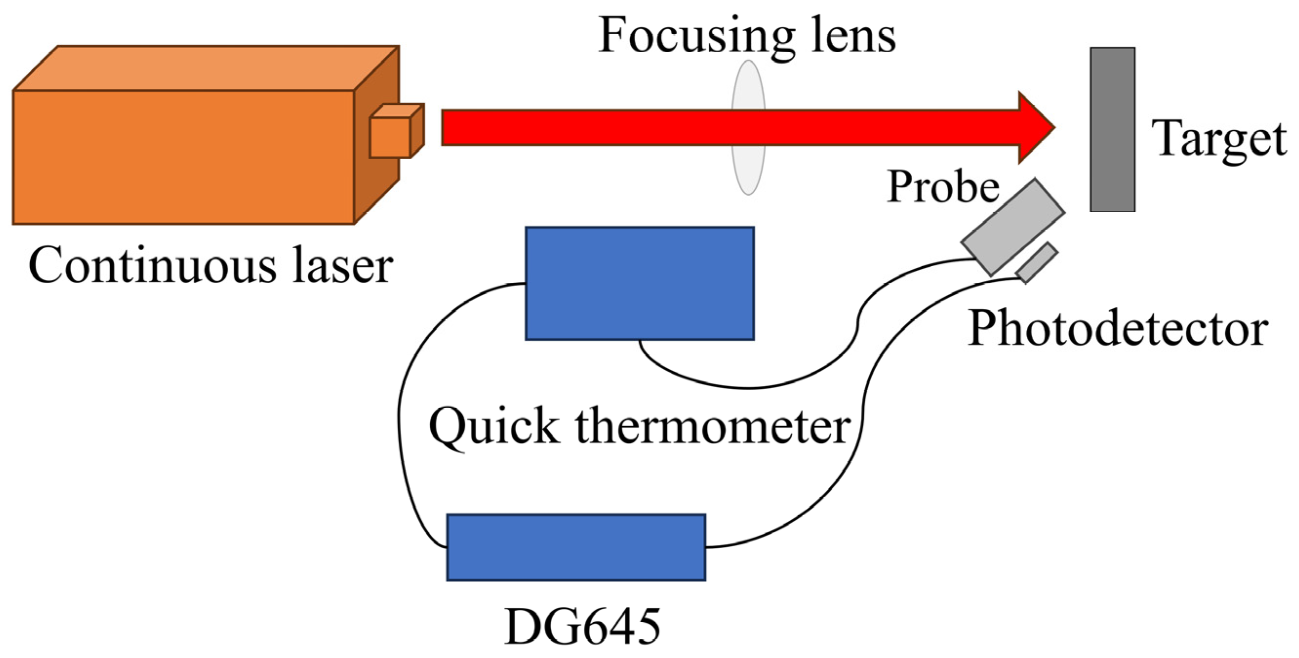
3. Experiment
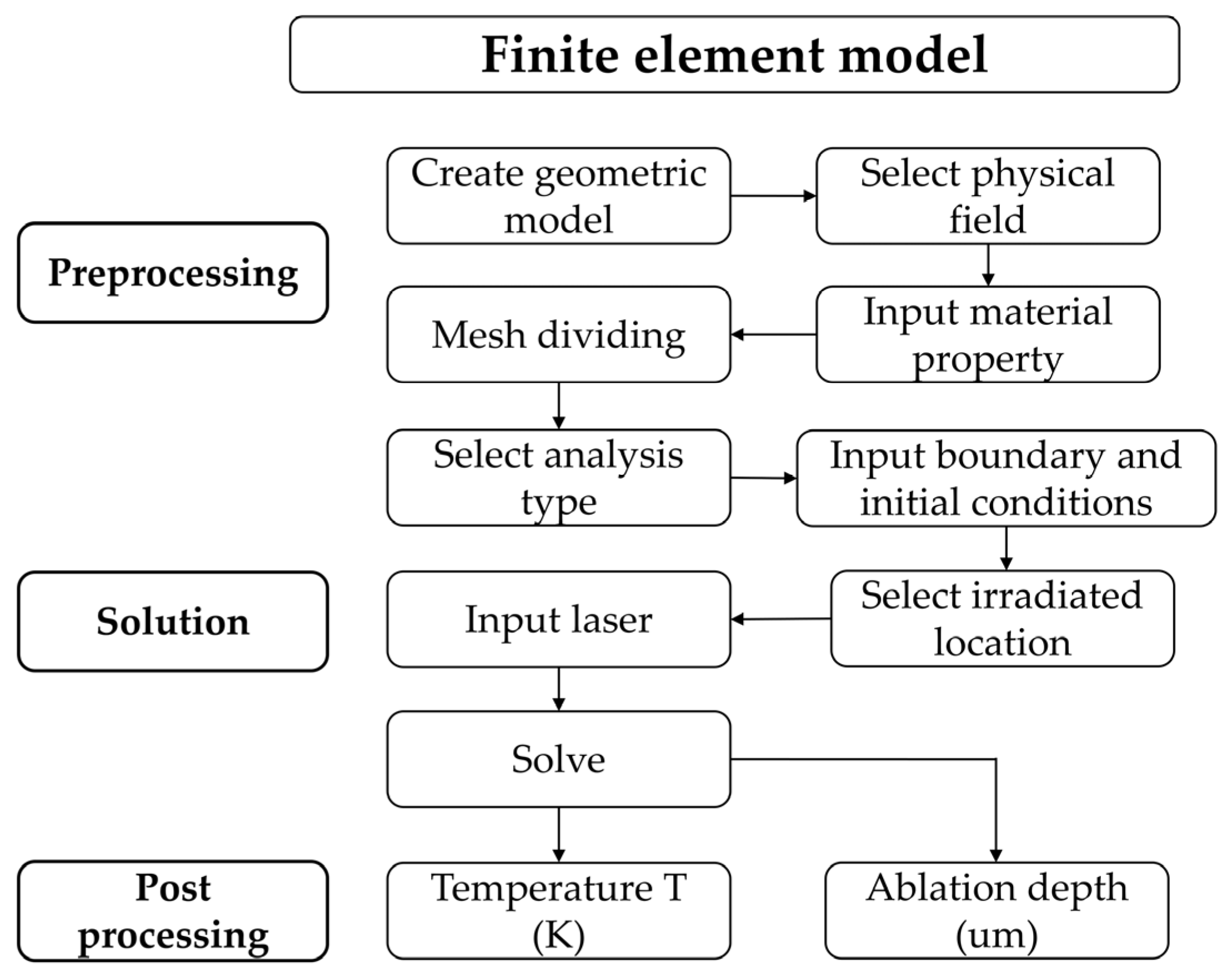
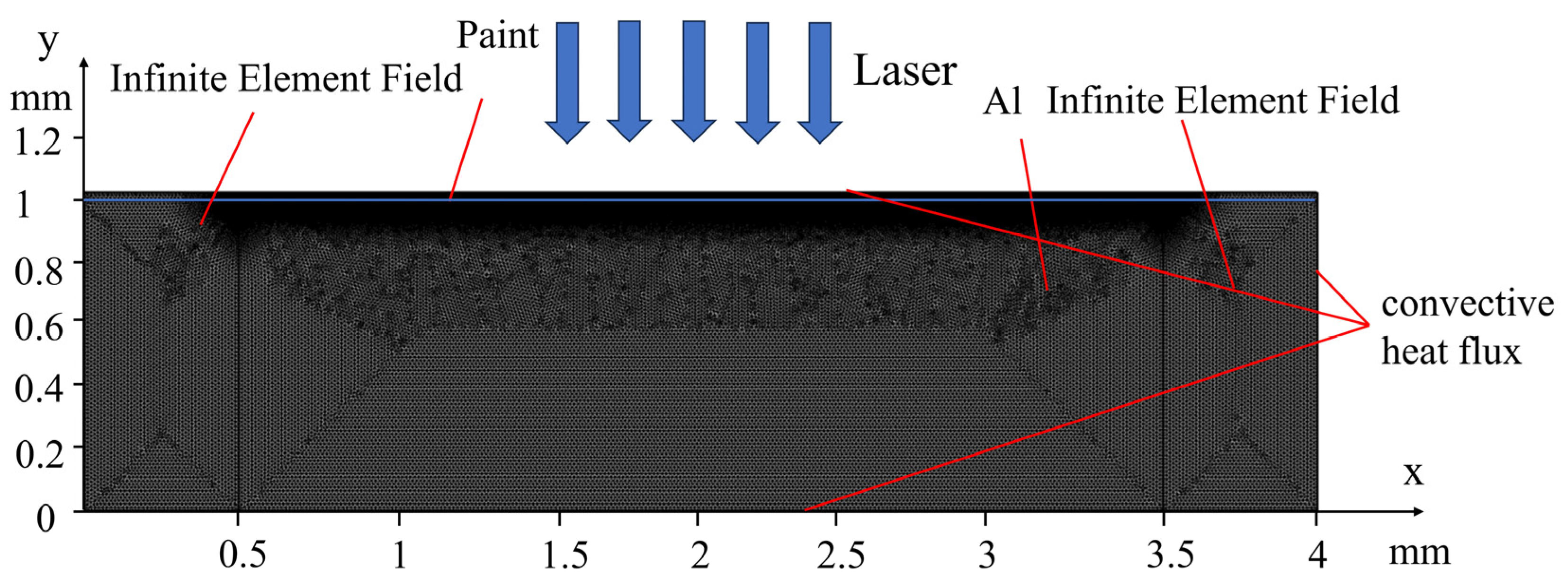
4. Numerical Model
5. Results and Discussion
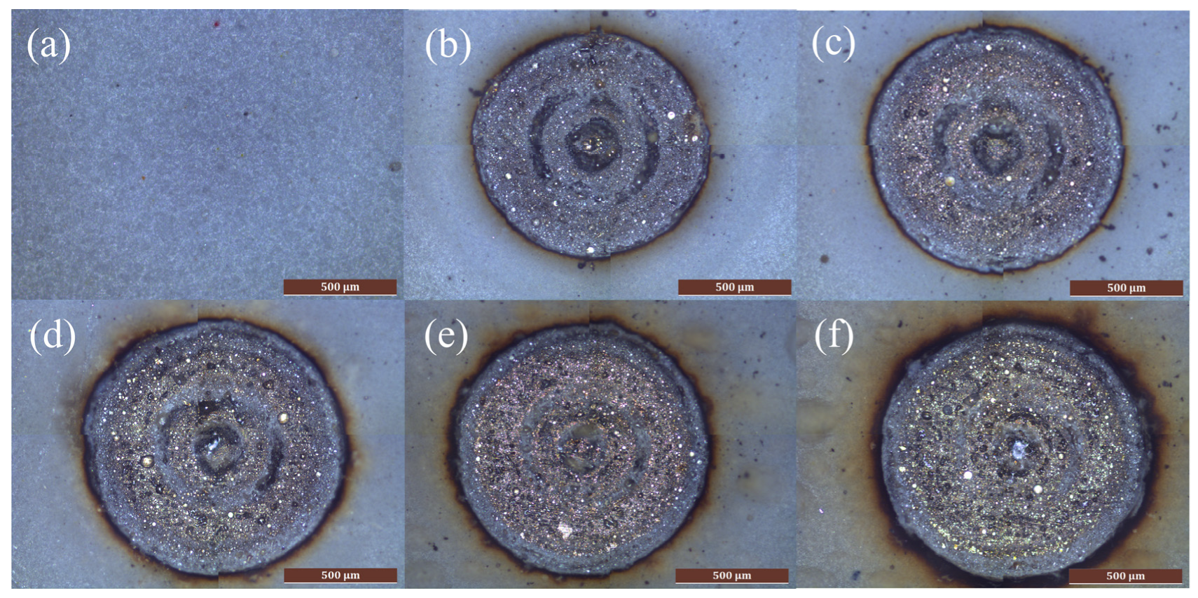
5.1. Surface Morphology
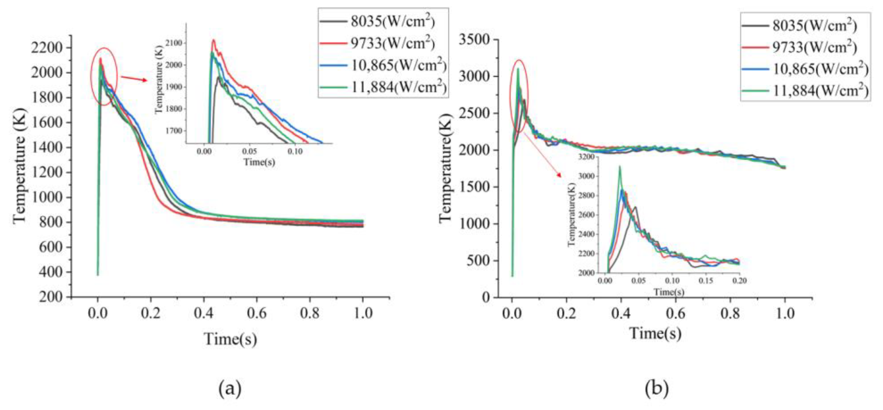
5.2. Surface Temperature
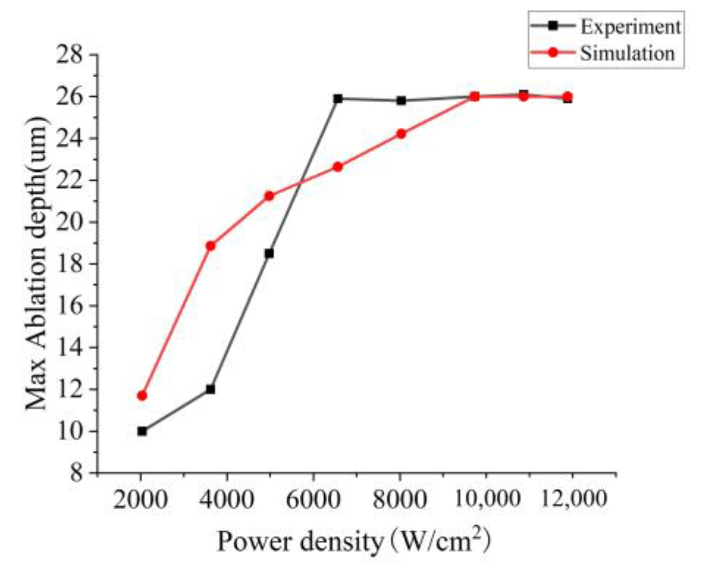
5.3. Ablation Depth
5.4. 3D Surface Profile
6. Conclusions
Author Contributions
Funding
Institutional Review Board Statement
Informed Consent Statement
Data Availability Statement
Conflicts of Interest
References
- Park, J.E.; Kyung, K.S.; Moon, M.G.; Yun, I.S.; Eum, M.J. Applicability evaluation of clean laser system in surface preparation on steel. Int. J. Steel Struct. 2020, 20, 1882–1890. [Google Scholar] [CrossRef]
- Barletta, M.; Gisario, A.; Tagliaferri, V. Advance in paint stripping from aluminium substrates. J. Mater. Process. Technol. 2006, 173, 232–239. [Google Scholar] [CrossRef]
- Schmidt, M.J.J.; Li, L.; Spencer, J.T. An investigation into the feasibility and characteristics of using a 2.5 kW high power diode laser for paint stripping. J. Mater. Process. Technol. 2003, 138, 109–115. [Google Scholar] [CrossRef]
- Turner, M.W.; Crouse, P.L.; Li, L.; Smith, A.J.E. Investigation into CO2 laser cleaning of titanium alloys for gas-turbine component manufacture. Appl. Surf. Sci. 2006, 252, 4798–4802. [Google Scholar] [CrossRef]
- Chen, G.X.; Kwee, T.J.; Tan, K.P.; Choo, Y.S.; Hong, M.H. Laser cleaning of steel for paint removal. Appl. Phys. A 2010, 101, 249–253. [Google Scholar] [CrossRef]
- Madhukar, Y.K.; Mullick, S.; Shukla, D.K.; Kumar, S.; Nath, A.K. Effect of laser operating mode in paint removal with a fiber laser. Appl. Surf. Sci. 2013, 264, 892–901. [Google Scholar] [CrossRef]
- Madhukar, Y.K.; Mullick, S.; Nath, A.K. Development of a water-jet assisted laser paint removal process. Appl. Surf. Sci. 2013, 286, 192–205. [Google Scholar] [CrossRef]
- Guerrero, G.R.; Sevilla, L.; Soriano, C. Laser and pyrolysis removal of fluorinated ethylene propylene thin layers applied on en AW-5251 aluminium substrates. Appl. Surf. Sci. 2015, 353, 686–692. [Google Scholar] [CrossRef]
- Anthofer, A.; Lippmann, W.; Hurtado, A. Laser decontamination of epoxy painted concrete surfaces in nuclear plants. Opt. Laser Technol. 2014, 57, 119–128. [Google Scholar] [CrossRef]
- Anthofer, A.; Kögler, P.; Friedrich, C.; Lippmann, W.; Hurtado, A. Laser decontamination and decomposition of PCB-containing paint. Opt. Laser Technol. 2017, 87, 31–42. [Google Scholar] [CrossRef]
- Lu, Y.; Yang, L.; Wang, Y.; Chen, H.; Guo, B.; Tian, Z. Paint removal on the 5A06 aluminum alloy using a continuous wave fiber laser. Coatings 2019, 9, 488. [Google Scholar] [CrossRef]
- Penide, J.; Quintero, F.; Riveiro, A.; Sánchez-Castillo, A.; Comesaña, R.; del Val, J.; Lusquiños, F.; Pou, J. Removal of graffiti from quarry stone by high power diode laser. Opt. Lasers Eng. 2013, 51, 364–370. [Google Scholar] [CrossRef]
- Provines, J.; Rickard, R.; Sharp, S. Evaluation of a Continuous Laser Ablation Coating Removal Device for Steel Bridges. Transp. Res. Rec. 2022, 2676, 767–778. [Google Scholar] [CrossRef]
- Li, W.; Su, X.; Gu, J.; Jin, Y.; Xu, J.; Guo, B. Removal Mechanisms and Microstructure Characteristics of Laser Paint Stripping on Aircraft Skin Surface. Photonics 2023, 10, 96. [Google Scholar] [CrossRef]
- Zhao, Z.; Liu, X.; Chen, Z.; Tian, Y.; Chen, M.; Liu, L.; Song, F. Evaluation of laser cleaning effect for the removal of paint on aluminum alloys. Int. J. Adv. Manuf. Technol. 2023, 126, 3193–3203. [Google Scholar] [CrossRef]
- Liu, Q.; Zhao, Y.; Meng, J.; Wang, K.; Zhao, G.; Li, L.; Zheng, Z.; Liu, G.; Cao, C.; Dai, D. Research on the Removal Mechanism of Resin-Based Coatings by Water Jet-Guided Quasi-Continuous Laser Cleaning. Appl. Sci. 2022, 12, 5450. [Google Scholar] [CrossRef]
- Bauerle, D. Laser Processing and Chemistry, 4th ed.; Springer: Heidelberg, Germany, 2011; p. 21. [Google Scholar]
- Ben-Yakar, A.; Byer, R.L. Femtosecond laser ablation properties of borosilicate glass. J. Appl. Phys. 2004, 96, 5316–5323. [Google Scholar] [CrossRef]
- Chen, Y.Z.; Xie, X.D.; Xiao, X.P. An evolving model of surface profile produced by nanosecond laser ablation on aluminum alloy. J. Laser Micro Nanoeng. 2019, 14, 152–160. [Google Scholar]
- Qin, R.; Yang, H. Numerical Simulation of Temperature Field for Laser Removal of Oxide Layer of AlSi10Mg (Fe) Aluminum Alloy. Integr. Ferroelectr. 2022, 229, 158–172. [Google Scholar] [CrossRef]
- Esfahani, J.A.; Sousa, A.C. Ignition of epoxy by a high radiation source. A numerical study. Int. J. Therm. Sci. 1999, 38, 315–323. [Google Scholar] [CrossRef]
- Ohkubo, T.; Sato, Y.; Matsunaga, E.I.; Tsukamoto, M. Thermal effect of laser ablation on the surface of carbon fiber reinforced plastic during laser processing. Appl. Phys. A 2018, 124, 149. [Google Scholar] [CrossRef]
- Zou, W.F.; Xie, Y.M.; Xiao, X.; Zeng, X.; Zeng, X.Z.; Luo, Y. Application of thermal stress model to paint removal by Q-switched Nd: YAG laser. Chin. Phys. B 2014, 23, 433–438. [Google Scholar] [CrossRef]
- Papadopoulos, K.; Tserpes, K. Analytical and Numerical Modeling of Stress Field and Fracture in Aluminum/Epoxy Interface Subjected to Laser Shock Wave: Application to Paint Stripping. Materials 2022, 15, 3423. [Google Scholar] [CrossRef] [PubMed]
- Lu, X.D. Study on Ignition and Combustion Characteristics of Polymer. Master’s Thesis, Qingdao University of Science and Technology, Qingdao, China, 2007. [Google Scholar]
- Richter, A.; Nikrityuk, P.A.; Meyer, B. Three-dimensional calculation of a chemically reacting porous particle moving in a hot O2/CO2 atmosphere. Int. J. Heat Mass Transf. 2015, 83, 244–258. [Google Scholar] [CrossRef]
- Lascano, D.; Lerma-Canto, A.; Fombuena, V.; Balart, R.; Montanes, N.; Quiles-Carrillo, L. Kinetic analysis of the curing process of biobased epoxy resin from epoxidized linseed oil by dynamic differential scanning calorimetry. Polymers 2021, 13, 1279. [Google Scholar] [CrossRef]
- Stauch, R.; Maas, U. Transient detailed numerical simulation of the combustion of carbon particles. Int. J. Heat Mass Transf. 2009, 52, 4584–4591. [Google Scholar] [CrossRef]
- Roberts, D.E. Pulsed laser coating removal by detachment and ejection. Appl. Phys. A-Mater. Sci. Process 2004, 79, 1067–1070. [Google Scholar] [CrossRef]


| Properties | Paint | Carbon Shell | Aluminum Alloy [19] | Melting Aluminum Alloy [19] | Alumina [20] | Interface Layer |
|---|---|---|---|---|---|---|
| Specific heat capacity Cp (J/kg·K) | 1800 [21] | 1048 [22] | 1050 | 921 | 600 | 1200 |
| Thermal conductivity k (W/(m·K)) | 0.2 [23] | 0.1 | 223 | 106 | 27 | 13.55 |
| Density ρ (kg/m3) | 1700 [24] | 1005 [22,25] | 2549 | 2224 | 3600 | 2650 |
| Pre-exponential reaction constant A (m/s) | 3 × 10¹⁰ [21] | 3 × 10⁵ [26] | ||||
| Latent heat of fusion Lm (J/kg) | 3.89 × 10⁵ | |||||
| Reaction activation energy of gasification ΔE (kJ/mol) | 70 [27] | 149.7 [28] | ||||
| Latent heat of gasification Lv (J/kg) | 2.051 × 10⁵ [27] | 2.62 × 10⁷ [26] | 1.05 × 10⁷ | |||
| The absorption coefficient of the material α (1/m) | 5 × 10⁴ [29] | 2.5 × 10⁴ | ||||
| Emissivity ε (1) | 0.79 [21] | 0.09 | ||||
| Melting temperature Tm | 933 K | |||||
| Gasification temperature Tv (°C) | 500 | 600 |
Disclaimer/Publisher’s Note: The statements, opinions and data contained in all publications are solely those of the individual author(s) and contributor(s) and not of MDPI and/or the editor(s). MDPI and/or the editor(s) disclaim responsibility for any injury to people or property resulting from any ideas, methods, instructions or products referred to in the content. |
© 2024 by the authors. Licensee MDPI, Basel, Switzerland. This article is an open access article distributed under the terms and conditions of the Creative Commons Attribution (CC BY) license (https://creativecommons.org/licenses/by/4.0/).
Share and Cite
Li, Y.; Li, J.; Dong, H.; Zhang, W.; Jin, G. Simulation and Experimental Study on Continuous Wave Fiber Laser Removal of Epoxy Resin Paint Film on the Surface of 6061 Aluminum Alloy. Photonics 2024, 11, 82. https://doi.org/10.3390/photonics11010082
Li Y, Li J, Dong H, Zhang W, Jin G. Simulation and Experimental Study on Continuous Wave Fiber Laser Removal of Epoxy Resin Paint Film on the Surface of 6061 Aluminum Alloy. Photonics. 2024; 11(1):82. https://doi.org/10.3390/photonics11010082
Chicago/Turabian StyleLi, Yahui, Jingyi Li, Hang Dong, Wei Zhang, and Guangyong Jin. 2024. "Simulation and Experimental Study on Continuous Wave Fiber Laser Removal of Epoxy Resin Paint Film on the Surface of 6061 Aluminum Alloy" Photonics 11, no. 1: 82. https://doi.org/10.3390/photonics11010082
APA StyleLi, Y., Li, J., Dong, H., Zhang, W., & Jin, G. (2024). Simulation and Experimental Study on Continuous Wave Fiber Laser Removal of Epoxy Resin Paint Film on the Surface of 6061 Aluminum Alloy. Photonics, 11(1), 82. https://doi.org/10.3390/photonics11010082