Communication

Broadband Optical Frequency Comb Generation Utilizing a Gain-Switched Weak-Resonant-Cavity Fabry–Perot Laser Diode under Multi-Wavelength Optical Injection

by
Yuhong Tao
1,2,
Qiupin Wang
1,2,
Pu Ou
1,2,
Guangqiong Xia
1,2 and
Zhengmao Wu
1,2,*
1
School of Physical Science and Technology, Southwest University, Chongqing 400715, China
2
Chongqing Key Laboratory of Micro & Nano Structure Optoelectronics, Southwest University, Chongqing 400715, China
*
Author to whom correspondence should be addressed.
Photonics 2024, 11(10), 912; https://doi.org/10.3390/photonics11100912
Submission received: 8 September 2024 / Revised: 23 September 2024 / Accepted: 25 September 2024 / Published: 27 September 2024

Abstract

:
We propose and experimentally demonstrate an approach for generating a wideband optical frequency comb (OFC) featuring multiple comb lines and wavelength tunability based on a gain-switched weak-resonant-cavity Fabry–Perot laser diode (WRC-FPLD) under multi-wavelength optical injection. The longitudinal mode interval of the utilized WRC-FPLD is about 0.28 nm (35.0 GHz), and its relaxation oscillation frequency is about 2.0 GHz at 1.15 times the threshold current. Under current modulation with a power of 20.00 dBm and a frequency of 2.0 GHz, the WRC-FPLD is driven into the gain-switched state. By further introducing multi-wavelength injection light (MWIL) containing four power equalization comb lines with an interval of 0.56 nm, a wideband OFC featuring multiple comb lines and wavelength tenability can be obtained. The experimental results demonstrate that by gradually increasing the injection’s optical power, the number of produced OFC lines initially increases and then decreases. By meticulously adjusting the wavelengths of the MWIL and carefully selecting the matched injection power, the broadband OFC can be tuned across an extensive spectral range. Under optimized operation parameters, an OFC with 147 lines, and a bandwidth of approximately 292 GHz within a 10 dB amplitude, variation is achieved. In this case, the measured single-sideband phase noise at the fundamental frequency is about −115 dBc/Hz @ 10 kHz, indicating that the comb lines possess good stability and strong coherence.

1. Introduction

Optical frequency combs (OFCs) [1], serving as a source of multi-wavelength light, are characterized by a series of discrete and coherent spectral lines that are uniformly spaced in the frequency spectrum. Concurrently, in the time domain, the OFC manifests as a train of pulses with consistent time intervals. The OFC’s unique properties allow it to be applied in various fields, including spectroscopy [2,3], atomic clocks [4,5], optical communication [6,7], and arbitrary waveform generation [8,9]. The main methods for producing an OFC include mode-locked lasers [10,11], electro-optic modulation [12,13], and optical injection-locked gain-switched (OI-GS) laser diodes [14,15]. Among these methods, the OFC-generated schemes based on OI-GS laser diodes receive additional attention due to their exceptional performances in terms of stability, tunability, and phase correlation [16,17,18].
The Fabry–Perot laser diode (FP-LD) possesses a relatively wide gain spectrum, which gives an OI-GS FP-LD the potential to generate a wideband OFC [19]. In recent years, various experimental schemes utilizing OI-GS FP-LDs to generate broadband OFCs have been reported. In 2011, Zhou et al. experimentally generated an OFC using an OI-GS FP-LD and subsequently expanded its bandwidth to about 160 GHz (16 comb lines) via a phase modulator [20]. In 2015, Pascual et al. demonstrated an OFC with a bandwidth exceeding 325 GHz (52 comb lines) by simultaneously injecting and locking two modes of a gain-switched (GS) FP-LD [21]. In 2021, Jain et al. reported an OFC with a bandwidth of approximately 100 GHz (nine comb lines), where the comb spacing and central wavelength can be tuned [16]. In 2023, Lakshmijayasimha et al. reported an OFC with a bandwidth exceeding 275 GHz (44 comb lines) via a GS FP-LD under multi-wavelength optical injection, where the multi-wavelength injection light (MWIL) contains 13 wavelength components, which is provided by an OI-GS distributed feedback semiconductor laser (DFB-SL) [22]. However, the aforementioned schemes face a challenge due to the relatively large mode spacing of the utilized FP-LDs, which makes it difficult for the injected light, at a specific wavelength, to effectively stimulate the adjacent longitudinal modes. As a result, both the bandwidth and the number of comb lines (NCL) of the generated OFCs are restricted. Compared to traditional FP-LDs, the weak-resonant-cavity Fabry–Perot laser diode (WRC-FPLD) possesses a longer cavity length and lower front-facet reflectivity [23,24], which leads to more compact mode spacing and a flatter gain spectrum. As a result, based on an OI-GS WRC-FPLD, it is expected that an OFC with a wider bandwidth and a greater NCL can be achieved.
In this work, based on a GS WRC-FPLD under multi-wavelength optical injection, we propose a scheme for generating an OFC with a wide bandwidth, multiple comb lines, and tunability. For such a scheme, via the four-wave mixing (FWM) effect in a DFB-SL under continuous light injection [25,26], a light source containing four wavelength components with an interval of 0.56 nm (twice the longitudinal mode spacing (0.28 nm) of the WRC-FPLD) is obtained and taken as the MWIL after undergoing power equalization. By inspecting the performances of the generated OFC under different injection parameters, the influences of the injection parameters on the performances of the generated OFC are revealed. Under optimized injection conditions, an OFC comprising 147 lines with a bandwidth of approximately 292 GHz under a free spectral range (FSR) of 2 GHz is obtained. Based on this proposed scheme, the generated OFC has some unique virtues including a small FSR, a large bandwidth, and tunability, and it possesses application prospects in a variety of fields such as high-density optical communication and spectroscopy.

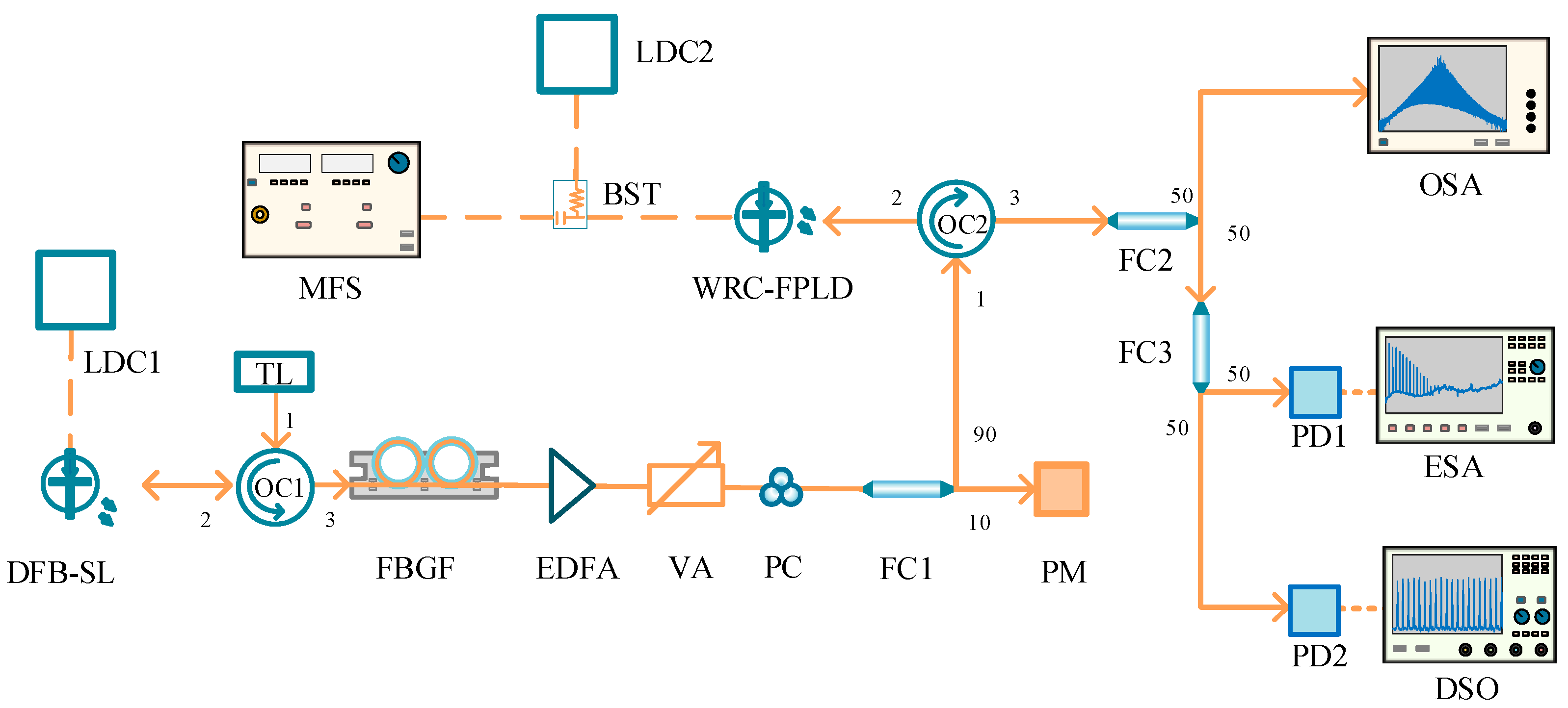
2. Experimental Setup and Theory

Figure 1 is the schematic diagram of the experimental system. A WRC-FPLD is powered by the combination of two currents through a T-type bias tee (BST, Picosecond, 5541A, 80 kHz–26 GHz, OH, USA), where one is a DC bias provided by a laser diode controller (LDC1, ILX-Lightwave, LDC-3724C, CA, USA) and the other is a sinusoidal modulation current at a frequency of fa supplied by a microwave frequency synthesizer (MFS, Agilent E8257C, Santa Clara, CA, USA). The WRC-FPLD adopts the compact and simple design of a TO-56-can package, which uses a set of a designed copper mount and a thermistor to reduce the influence of temperature variation on the laser [27,28,29]. Throughout the entire experimental process, the temperature of the WRC-FPLD is maintained at 17.15 °C by LDC1. The continuous light wave from a tunable laser (TL, Santec TSL-570, 1480–1640 nm, Aichi, Japan) is injected into a DFB-SL via an optical circulator (OC1). The DFB-SL is driven by another laser diode controller (LDC2, ILX-Lightwave, LDC-3908, CA, USA). Based on the FWM effect in the DFB-SL cavity, four coherent comb lines can be observed, for which there exist significant differences in the power amplitudes among the four comb lines. Subsequently, by sending them to a fiber Bragg grating filter (FBGF, ExFOXTM-50, QC, Canada) combined with an erbium-doped fiber amplifier (EDFA, Wuhan, China), power-balanced MWIL containing four comb lines can be obtained through selecting suitable operating parameters. The MWIL successively passes through a variable attenuator (VA), a polarization controller (PC), a 10:90 fiber coupler (FC1), and an optical circulator (OC2), and is then injected into the WRC-FPLD. The injection light power is monitored via a power meter (PM, Thorlabs, PM100D, NJ, USA). The optical signal output from the WRC-FPLD is split into two branches by a 50:50 fiber coupler (FC2). One branch is connected to an optical spectrum analyzer (OSA, Aragon Photonics BOSA lite+, 20 MHz resolution, Zaragoza, Spain) for spectral analysis. The other branch is further divided into two paths by another 50:50 fiber coupler (FC3). One path is sent to an electrical spectrum analyzer (ESA, Rohde & Schwarz FSW, 67.0 GHz bandwidth, Munich, Germany) after being converted to an electrical signal by a photodetector (PD1, U2T-XPDV2150R, 50.0 GHz bandwidth, Sunnyvale, CA, USA). The other path is connected to another photodetector (PD2, New Focus 1544B, 12.0 GHz bandwidth, CA, USA) and is then sent to a digital storage oscilloscope (DSO, Agilent X91604A, 16.0 GHz bandwidth, Santa Clara, CA, USA) for time-series measurement.
Based on the multi-mode rate equations describing the FP-LD [30], the theory model for a GS WRC-FPLD under multi-wavelength optical injection can be established after further considering the effects of current modulation and optical injection. The rate equations for a GS WRC-FPLD under multi-wavelength optical injection can be described as
d E m ( t ) dt = 1 2 ( 1 + i α ) [ G m γ ] E m ( t ) + j = 1 4 k m ,   j E j i n j exp ( i Δ ω m ,   j t ) + 2 β N ( t ) ζ m ( t ) ,
d N ( t ) dt = I b i a s ( 1 + a sin ( 2 π f a t ) ) q 1 τ n N ( t ) m = 1 M G m | E m ( t ) | 2 ,
where Em(t) and N(t) are the slow variable field amplitude for the mth longitudinal mode and carrier number, respectively. E j i n j is the slow variable field amplitude of the jth injection light, and km,j is the injection strength for the mth longitudinal mode subject to the jth injection light. Ibias is the bias current, α is the linewidth enhancement factor, and γ is the cavity decay rate. Δωm,j is the frequency detuning between the frequency of the mth longitudinal mode and the jth injection light. Here, we assume that the injected light contains four wavelengths. β and ζm represent the spontaneous radiation factor and spontaneous radiation noise, respectively. a is the modulation amplitude, and fa is the modulation frequency. q represents the charge of an electron, and τn is the photon lifetime. M represents the total mode number that needs to be considered. Gm is the gain of the mth longitudinal mode, which can be described as
G m = g c ( N ( t ) N 0 ) 1 + ε m = 1 M | E m ( t ) | 2 [ 1 ( m m c Δ f g Δ f L ) 2 ] ,
where gc and ε are the differential gain coefficient and gain saturation coefficient, respectively. N0 is the transparency carrier number. mc is the order of the strongest longitudinal mode, ΔfL is the longitudinal mode spacing of the laser, and Δfg represents the gain bandwidth.
Based on Equations (1)–(3), the output characteristics of a GS WRC-FPLD under multi-wavelength optical injection can be analyzed numerically.

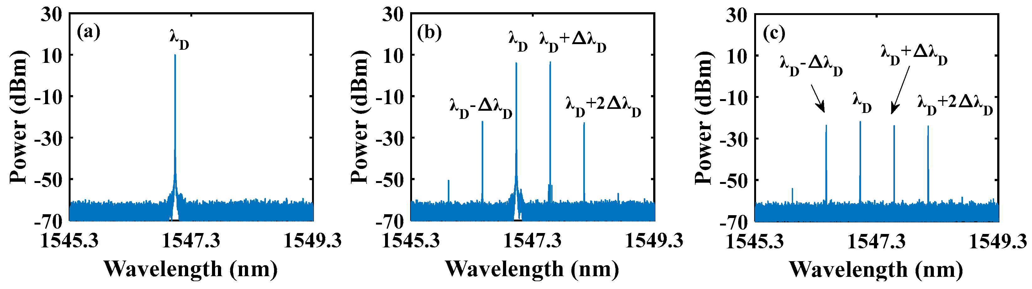
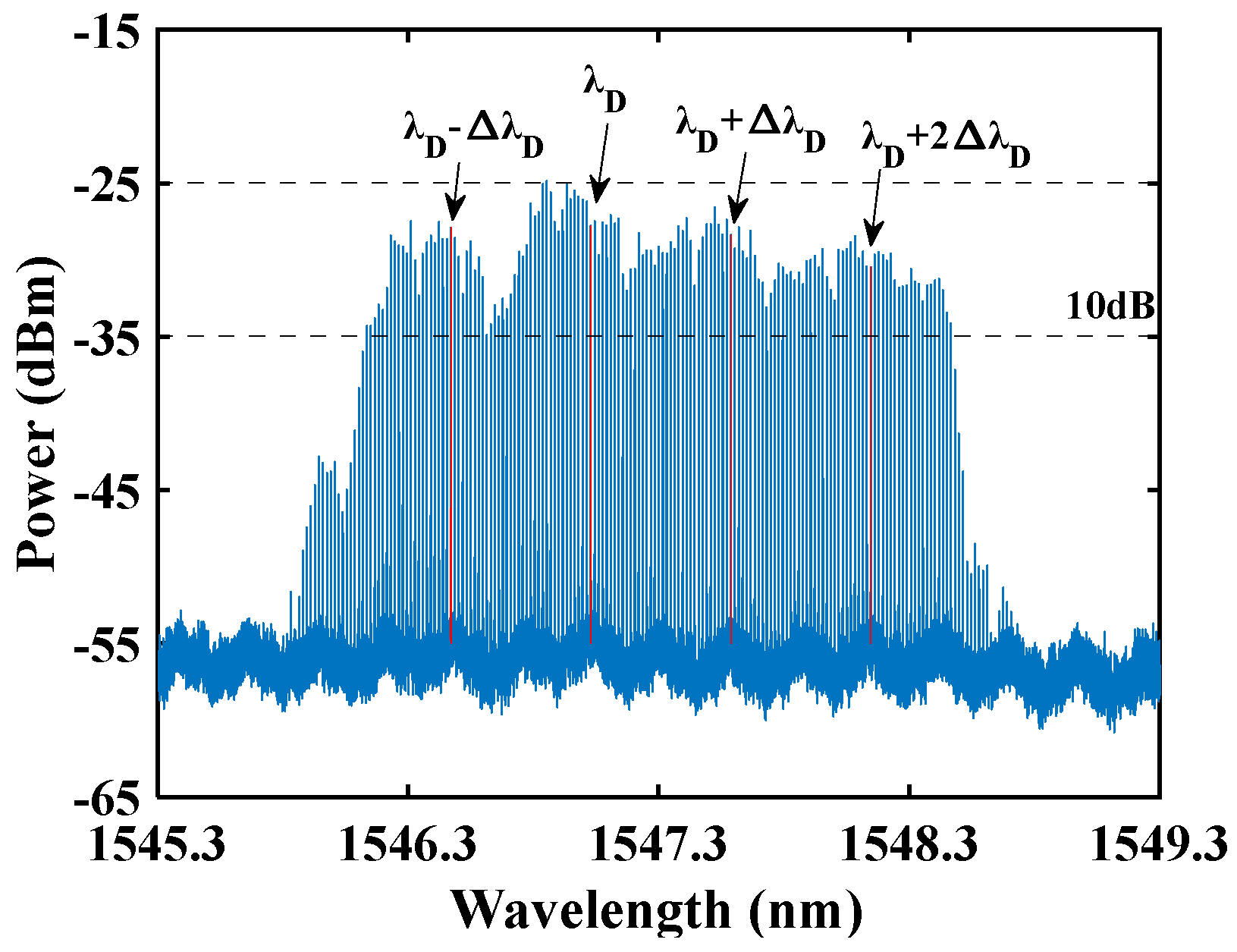
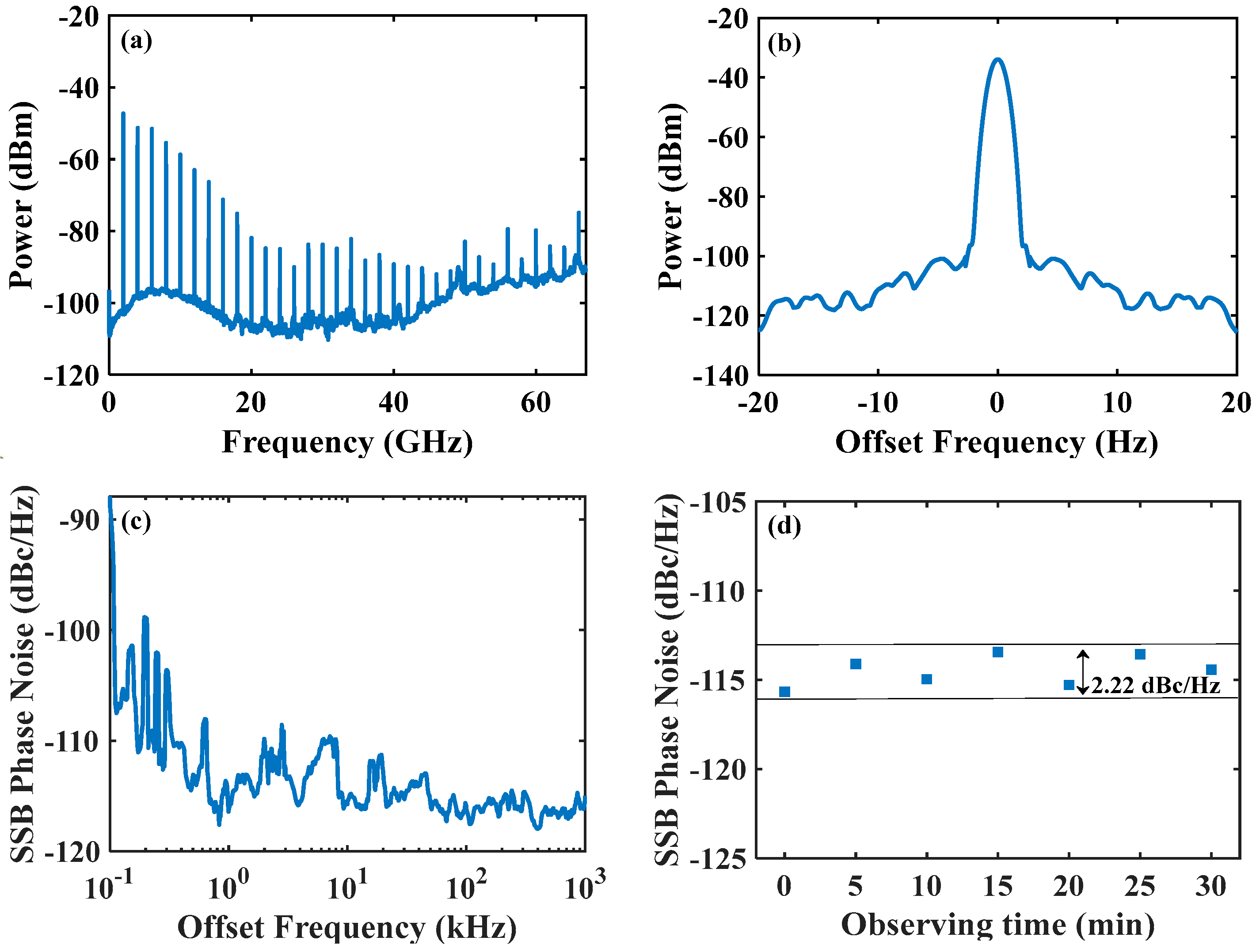
3. Results and Discussion

First, we analyze the fundamental properties of the WRC-FPLD utilized in this work. Figure 2 illustrates the P-I curve of the free-running WRC-FPLD, along with its optical spectrum under a bias current of 52.00 mA. As shown in Figure 2a, the threshold current (Ith) for the WRC-FPLD is approximately 45.00 mA. Under the bias current (Ibias) set at 52.00 mA (~1.15 Ith), the output power reaches 0.409 mW, and the corresponding optical spectrum is presented in Figure 2b. The peak wavelength is located at 1547.0899 nm, and the optical spectrum covers approximately 40 nm (from 1525 nm to 1565 nm). The wavelength spacing (Δλw) between two adjacent longitudinal modes is about 0.28 nm (corresponding to a frequency spacing ΔνW ~35 GHz), which is determined by the optical length of the active region in the WRC-FPLD. Through accurately designing the optical length of the active region combined with precisely controlling its temperature, the frequency spacing between two adjacent longitudinal modes in the WRC-FPLD can be matched with the telecom channel standards. In this work, we take the WRC-FPLD biased at 52.00 mA as an example to demonstrate the generation of the OFC after introducing current modulation and multi-wavelength optical injection. Through experimental measurement, it was found that the relaxation oscillation frequency of the WRC-FPLD biased at 52.00 mA is approximately 2.0 GHz. As a result, a modulation signal with a frequency of 2.0 GHz is employed to drive the WRC-FPLD into a GS state.
Next, we examine the output characteristics of the WRC-FPLD under current modulation. Figure 3 gives the optical spectra (first column), time series (second column), and power spectra (third column) of the WRC-FPLD output under current modulation with a frequency fa = 2.0 GHz and different power levels. For a modulation power Pm = 0 (Figure 3(a1–a3)), the WRC-FPLD operates at a free-running state. A series of longitudinal modes emerge in the optical spectrum, and the time series displays randomness and irregularity. Moreover, the power spectrum is close to the noise level except for a peak at around 2.0 GHz, corresponding to the relaxation oscillation frequency of the WRC-FPLD. For Pm = 0.00 dBm (Figure 3(b1–b3)), the longitudinal modes in the optical spectrum are broadened without discernible comb lines. The time series manifests as pulses with a repeat period of T = 0.5 ns (=1/fa) and random fluctuations in peak power. The power spectrum reveals the presence of beat frequency signals, originating from the periodic nature of the modulation signal. Additionally, the continuous noise level is elevated due to incoherent time jitter between pulses caused by varying spontaneous emission during the pulse recovery period [31]. These characteristics indicate that the WRC-FPLD begins to enter the GS state. The GS state refers to repeated toggling of the gain “on” and “off” states in a laser under a high-frequency alternating current, which results in the output power switching between “on” and “off” states. As a result, the output of the laser is in the form of pulses [32]. For Pm = 20.00 dBm (Figure 3(c1–c3)), the optical spectrum becomes flatter, and the time series manifests as pulses with a stronger peak power. Meanwhile, much higher-order harmonics appear in the power spectrum, and the continuous noise level is obviously enhanced. Under this case, the WRC-FPLD exhibits the typical characteristics of the GS state. In the following, we will utilize the WRC-FPLD in a typical GS state to generate a high-quality OFC through introducing multi-wavelength optical injection.
In order to simultaneously lock multiple modes of the WRC-FPLD for generating an OFC with a wide bandwidth, the spacing between the comb lines of the MWIL is required to be an integer multiple of the longitudinal mode spacing Δλw (=0.28 nm) of the WRC-FPLD. Our previous research has demonstrated that the NCL of the OFC generated by a GS WRC-FPLD under single-wavelength light injection varies periodically with the injected light wavelength, and the period is the same as the spacing between longitudinal modes [33]. Meanwhile, the bandwidth of the generated OFC can exceed the longitudinal mode spacing of the WRC-FPLD. Therefore, it is appropriate that the comb line spacing (ΔλD) of the MWIL is set at double the mode spacing (2Δλw = 0.56 nm). In this work, the MWIL is generated via the four-wave mixing (FWM) effect in a DFB-SL under optical injection and subsequently undergoes power equalization. Based on our previous experimental investigations [33], the injection light is best placed close to the strongest mode of the WRC-FPLD. Considering that the wavelength of the strongest longitudinal mode of the WRC-FPLD is located at 1547.0899 nm, the central wavelength of the DFB-SL (λD) is set at 1547.0294 nm. In this case, the optical spectrum of the free-running DFB-SL is given in Figure 4a. The CNR is greater than 60 dB. To obtain MWIL with ΔλD = 2Δλw (0.56 nm), the wavelength detuning between the tunable laser (TL) and the DFB-SL should be set at ΔλD (=2Δλw). Adopting continuous light with a power of 10.00 dBm and a wavelength of λD + ΔλD to inject into the DFB-SL, a light source containing multiple comb lines with wavelength spacing of ΔλD can be achieved based on the FWM effect, and its optical spectrum is provided in Figure 4b. Obviously, the amplitudes of the four comb lines differ significantly, which is not conducive to generating an OFC with high flatness. Further adopting an FBGF combined with an EDFA to implement power equalization, high-quality MWIL can be obtained, whose optical spectrum is given in Figure 4c. The four comb lines possess comparable power levels, and the CNR is approximately 40 dB.
Then, the high-quality MWIL is injected into the GS WRC-FPLD operating at the state shown in Figure 3(c1–c3). Through adjusting the gain of the EDFA and the attenuation rate of the VA, the injection power (Pinj) can be controlled. Under Pinj = 4.982 μW, the optical spectrum of the GS WRC-FPLD under multi-wavelength optical injection with λD = 1547.0294 nm is displayed in Figure 5. The generated OFC consists of 147 comb lines with a CNR greater than 20 dB, and its bandwidth is approximately 292 GHz. The reason for generating a broadband OFC through introducing MWIL is as follows. On one hand, the interaction between MWIL and the cavity’s longitudinal modes facilitates the coupling among adjacent modes, which can maintain a stable phase relationship among them. Therefore, the overall stability of the laser output is improved, and the comb lines with a high CNR can be achieved. On the other hand, the enhanced FWM effect, stimulated by the interaction of multiple wavelengths, broadens the output optical spectrum. As a result, through introducing MWIL to achieve the locking of ten adjacent longitudinal modes, an OFC with a bandwidth of approximately 292 GHz within a 10 dB amplitude variation is generated. It should be pointed out that when maintaining comb line wavelength spacing of 0.56 nm and tuning the wavelengths of MWIL, quasi-continuous tuning of the OFC’s central wavelength in the range of 1525 nm to 1565 nm can be realized.
Figure 5 is obtained under Pinj = 4.982 μW. Our experimental results demonstrate that the number of comb lines in the output of the OI-GS WRC-FPLD is dependent on the injection power. Figure 6a presents the number of comb lines (NCL) of OFC output from the OI-GS WRC-FPLD varied with the injection power under λD = 1547.0294 nm. It should be noted that the values are obtained from five sets of measurements taken after completely shutting down and restarting the experimental system. As shown in Figure 6a, with the increase in injection power, the number of OFC comb lines shows a trend of increasing first and then decreasing. However, the variation in the number of comb lines is relatively small. When Pinj = 4.982 μW, the number of comb lines in the OFC reaches its maximum value at 147, and its optical spectrum is shown in Figure 5. Figure 6b shows the power variation of different comb lines of the generated OFC with the injection power. With the increase in injection power, the power of different comb lines gradually rises. From this diagram, it can also be observed that the power fluctuations from multiple measurements for each of the comb lines are relatively small, which indicates that our proposal for generating an OFC possesses good reproducibility.
Finally, we discuss the characteristics of the frequency spectrum for the OFC in Figure 5, which is presented in Figure 7. From the power spectrum (Figure 7a), it can be seen that compared to the GS state shown in Figure 3(c3), the continuous noise level at higher frequencies has been suppressed. Moreover, much higher-order beat frequency signals can be observed. As a result, after introducing MWIL, the coherence among pulses has been enhanced. As previously mentioned, the “off” state in GS lasers causes the pulses to be completely disconnected, and each new pulse established by spontaneous emission of photons possesses a random initial phase. However, after introducing MWIL, the externally injected photons serve as a seed from which the pulses are derived. Such a specific phase correlation between successive pulses leads to noise suppression effects [34]. To characterize the coherence and stability of the obtained OFC, we measure the spectral distribution near the center frequency of the fundamental signal in the power spectrum and the single-sideband (SSB) phase noise of the fundamental signal, which are given in Figure 7b,c, respectively. As shown in Figure 7b, the CNR is greater than 60 dB and the 3 dB linewidth is approximately 1 Hz. The SSB phase noise of the fundamental signal (shown in Figure 7c) is approximately −115 dBc/Hz @ 10 kHz. Therefore, the OFC generated based on the OI-GS WRC-FPLD exhibits high coherence and stability. Figure 7d gives the SSB phase noise of the fundamental signal at a 10 kHz frequency offset as a function of the observing time. Over a 30 min observation window with an interval of 5 min, the SSB phase noise maintains at a fluctuation below 2.22 dBc/Hz, which means that the generated OFC possesses long-term stability.
For comparison, Table 1 summarizes the related experimental schemes for generating the broadband OFC based on the OI-GS FP-LD. It can be found that the OFC generated in this work possesses a larger NCL and a smaller FSR.

4. Conclusions

In summary, we experimentally demonstrated broadband OFC generation utilizing a gain-switched WRC-FPLD under multi-wavelength optical injection. Utilizing the FWM effect of the DFB-SL under continuous light injection, coherent MWIL with spacing that is twice the mode spacing of the WRC-FPLD is generated. After undergoing power equalization, the MWIL is introduced to lock multiple modes of the GS WRC-FPLD for generating the broadband OFC. The experimental results show that with the increase in MWIL power, the number of comb lines of the generated OFC exhibits a trend of increasing first and then decreasing. Under optimized operating parameters, an OFC with 147 comb lines and a bandwidth of approximately 292 GHz is generated, for which the 3 dB linewidth of the beat signal fundamental frequency is approximately 1 Hz, and the SSB phase noise is around −115 dBc/Hz @ 10 kHz. Since the generated OFC based on this proposed scheme possesses some special advantages, it is expected that this scheme has potential applications in some fields, such as high-density optical communication and spectroscopy.

Author Contributions

Conceptualization, Y.T. and Z.W.; methodology, Y.T. and Q.W.; validation, Y.T., Q.W. and P.O.; formal analysis, Y.T.; investigation, Y.T.; resources, Z.W. and G.X.; data curation, Y.T.; writing—original draft preparation, Y.T. and G.X.; writing—review and editing, Y.T. and G.X.; visualization, Y.T.; supervision, Z.W. and G.X.; project administration, Z.W. and G.X.; funding acquisition, Z.W., G.X. and Q.W. All authors have read and agreed to the published version of the manuscript.

Funding

This study was funded by the National Natural Science Foundation of China (62335015, 61875167), the Chongqing Natural Science Foundation (CSTB2022NSCQ-MSX0313), and the Postgraduates’ Research and Innovation Project of Chongqing (CYB23109).

Institutional Review Board Statement

Not applicable.

Informed Consent Statement

Not applicable.

Data Availability Statement

The original contributions presented in this study are included in the article, and further inquiries can be directed to the corresponding author.

Conflicts of Interest

The authors declare no conflicts of interest.

References

  1. Fortier, T.; Baumann, E. 20 years of developments in optical frequency comb technology and applications. Commun. Phys. 2019, 2, 153. [Google Scholar] [CrossRef]
  2. Holzwarth, R.; Udem, T.; Hänsch, T.W.; Knight, J.C.; Wadsworth, W.J.; Russell, P.S.J. Optical frequency synthesizer for precision spectroscopy. Phys. Rev. Lett. 2000, 85, 2264–2267. [Google Scholar] [CrossRef]
  3. Wang, Q.; Wang, Z.; Zhang, H.; Jiang, S.L.; Wang, Y.Y.; Jin, W.; Ren, W. Dual-comb photothermal spectroscopy. Nat. Commun. 2022, 13, 2181. [Google Scholar] [CrossRef] [PubMed]
  4. Newman, Z.L.; Maurice, V.; Drake, T.; Stone, J.R.; Briles, T.C.; Spencer, D.T.; Fredrick, C.; Li, Q.; Westly, D.; Ilic, B.R.; et al. Architecture for the photonic integration of an optical atomic clock. Optica 2019, 6, 680–685. [Google Scholar] [CrossRef]
  5. Udem, T.; Holzwarth, R.; Hänsch, T.W. Optical frequency metrology. Nature 2002, 416, 233–237. [Google Scholar] [CrossRef]
  6. Pfeifle, J.; Vujicic, V.; Watts, R.T.; Schindler, P.C.; Weimann, C.; Zhou, R.; Freude, W.; Barry, L.P.; Koos, C. Flexible terabit/s Nyquist-WDM super-channels using a gain-switched comb source. Opt. Express 2015, 23, 724–738. [Google Scholar] [CrossRef] [PubMed]
  7. Browning, C.; Elwan, H.H.; Martin, E.P.; O’Duill, S.; Poette, J.; Sheridan, P.; Farhang, A.; Cabon, B.; Barry, L.P. Gain-Switched Optical Frequency Combs for Future Mobile Radio-Over-Fiber Millimeter-Wave Systems. J. Light. Technol. 2018, 36, 4602–4610. [Google Scholar] [CrossRef]
  8. Zhou, X.; Zheng, X.P.; Wen, H.; Zhang, H.Y.; Guo, Y.L.; Zhou, B.K. All optical arbitrary waveform generation by optical frequency comb based on cascading intensity modulation. Opt. Commun. 2011, 284, 3706–3710. [Google Scholar] [CrossRef]
  9. Li, P.L.; Ma, X.L.; Shi, W.H.; Xu, E.M. Optical arbitrary waveform generation based on multi-wavelength semiconductor fiber ring laser. Opt. Laser Technol. 2017, 94, 228–233. [Google Scholar] [CrossRef]
  10. Haus, H.A. Mode-locking of lasers. IEEE J. Sel. Top. Quantum Electron. 2000, 6, 1173–1185. [Google Scholar] [CrossRef]
  11. Jones, D.J.; Diddams, S.A.; Ranka, J.K.; Stentz, A.; Windeler, R.S.; Hall, J.L.; Cundiff, S.T. Carrier-Envelope Phase Control of Femtosecond Mode-Locked Lasers and Direct Optical Frequency Synthesis. Science 2000, 288, 635–639. [Google Scholar] [CrossRef] [PubMed]
  12. Li, D.; Wu, S.B.; Liu, Y.; Guo, Y.F. Flat optical frequency comb generation based on a dual-parallel Mach–Zehnder modulator and a single recirculation frequency shift loop. Appl. Opt. 2020, 59, 1916–1923. [Google Scholar] [CrossRef] [PubMed]
  13. Ujjwal; Kumar, R. Optical Frequency Comb Generator Employing Two Cascaded Frequency Modulators and Mach–Zehnder Modulator. Electronics 2023, 12, 2762. [Google Scholar] [CrossRef]
  14. Yang, W.Y.; Xia, G.Q.; Jiang, Z.F.; Deng, T.; Lin, X.D.; Jin, Y.H.; Xiao, Z.Z.; Yue, D.Z.; Hu, C.X.; Cui, B.; et al. Experimental investigation on wideband optical frequency comb generation based on a gain-switched 1550 nm multi-transverse mode vertical-cavity surface-emitting laser subject to dual optical injection. IEEE Access 2020, 8, 170203–170210. [Google Scholar] [CrossRef]
  15. Lakshmijayasimha, P.D.; Anandarajah, P.M.; Landais, P.; Kaszubowska-Anandarajah, A. Optical Frequency Comb Expansion Using Mutually Injection-Locked Gain-Switched Lasers. Appl. Sci. 2021, 11, 7108. [Google Scholar] [CrossRef]
  16. Jain, G.; Gutierrez-Pascual, D.; Wallace, M.; Donegan, J.; Anandarajah, P. Experimental Investigation of External Optical Injection and its Application in Gain-Switched Wavelength Tunable Optical Frequency Comb Generation. J. Light. Technol. 2021, 39, 5884–5895. [Google Scholar] [CrossRef]
  17. Zhang, J.H.; Fan, L.; Wu, Z.M.; Gou, C.H.; Luo, Y.; Xia, G.Q. Broadband and tunable optical frequency comb based on 1550 nm verticalcavity surface-emitting laser under pulsed current modulation and optical injection. Acta Phys. Sin. 2023, 72, 014207. [Google Scholar] [CrossRef]
  18. Ren, H.P.; Fan, L.; Liu, N.; Wu, Z.M.; Xia, G.Q. Generation of Broadband Optical Frequency Comb Based on a Gain-Switching 1550 nm Vertical-Cavity Surface-Emitting Laser under Optical Injection. Photonics 2020, 7, 95. [Google Scholar] [CrossRef]
  19. Pan, S.L.; Yao, J.P. Wideband and frequency-tunable microwave generation using an optoelectronic oscillator incorporating a Fabry–Perot laser diode with external optical injection. Opt. Lett. 2010, 35, 1911–1913. [Google Scholar] [CrossRef]
  20. Zhou, R.; Latkowski, S.; O’Carroll, J.; Phelan, R.; Barry, L.P.; Anandarajah, P. 40nm wavelength tunable gain-switched optical comb source. Opt. Express 2011, 19, B415–B420. [Google Scholar] [CrossRef]
  21. Pascual, M.D.G.; Zhou, R.; Smyth, F.; Shao, T.; Anandarajah, P.M.; Barry, L. Dual mode injection locking of a Fabry-Pérot laser for tunable broadband gain switched comb generation. In Proceedings of the 2015 European Conference on Optical Communication, Valencia, Spain, 27 September 2015. [Google Scholar]
  22. Lakshmijayasimha, P.D.; Kaszubowska-Anandarajah, A.; Srivastava, M.; Martin, E.P.; Anandarajah, P.M. Generation of a Wideband OFC by the Correlation of Multiple Modes of a Gain-Switched Fabry Pérot Laser. J. Light. Technol. 2023, 41, 5084–5090. [Google Scholar] [CrossRef]
  23. Lin, G.R.; Wang, H.L.; Lin, G.C.; Huang, Y.H.; Lin, Y.H.; Cheng, T.K. Comparison on Injection-Locked Fabry–Perot Laser Diode With Front-Facet Reflectivity of 1% and 30% for Optical Data Transmission in WDM-PON System. J. Light. Technol. 2009, 27, 2779–2785. [Google Scholar]
  24. Lin, S.Y.; Chi, Y.C.; Su, Y.C.; Li, Y.C.; Lin, G.R. An Injection-Locked Weak-Resonant-Cavity Laser Diode for Beyond-Bandwidth Encoded 10-Gb/s OOK Transmission. IEEE Photonics J. 2015, 7, 7200309. [Google Scholar] [CrossRef]
  25. Aldaya, I.; Gosset, C.; Wang, C.; Campuzano, G.; Grillot, F.; Castañón, G. Periodic and aperiodic pulse generation using optically injected DFB laser. Electron. Lett. 2015, 51, 280–282. [Google Scholar] [CrossRef]
  26. Zhang, T.T.; Xiong, J.T.; Zheng, J.L.; Chen, X.F.; Pu, T. Wideband tunable single bandpass microwave photonic filter based on FWM dynamics of optical-injected DFB laser. Electron. Lett. 2016, 52, 57–59. [Google Scholar] [CrossRef]
  27. Shih, T.T.; Tseng, P.H.; Lai, Y.Y.; Cheng, W.H. Compact TO-CAN Header With Bandwidth Excess 40 GHz. J. Light. Technol. 2011, 29, 2538–2544. [Google Scholar] [CrossRef]
  28. Chi, Y.C.; Li, Y.C.; Lin, G.R. Specific Jacket SMA-Connected TO-Can Package FPLD Transmitter With Direct Modulation Bandwidth Beyond 6 GHz for 256-QAM Single or Multisubcarrier OOFDM up to 15 Gb/s. J. Light. Technol. 2013, 31, 28–35. [Google Scholar] [CrossRef]
  29. Cheng, M.C.; Chi, Y.C.; Tsai, C.T.; Lin, C.Y.; Lin, G.R. TO-56-can packaged colorless WRC-FPLD for QAM OFDM transmission at 42 Gbit/s over 25-km SMF. Opt. Express 2015, 23, 22676–22690. [Google Scholar] [CrossRef]
  30. Yang, Q.; Wu, Z.M.; Wu, J.G.; Xia, G.Q. Influence of injection patterns on chaos synchronization performance between a multimode laser diode and a single-mode laser. Opt. Commun. 2008, 281, 5025–5030. [Google Scholar] [CrossRef]
  31. Rosado, A.; Pérez-Serrano, A.; Tijero, J.M.G.; Valle, Á.; Pesquera, L.; Esquivias, I. Experimental study of optical frequency comb generation in gain-switched semiconductor lasers. Opt. Laser Technol. 2018, 108, 542–550. [Google Scholar] [CrossRef]
  32. Peng, B.Y.; Yuan, C.Z.; Zhang, R.M.; Shen, S.; Zhang, Z.C.; Li, J.R.; Lin, Y.; Deng, G.W.; Wang, Y.; Song, H.Z.; et al. Progress in Gain-Switched Semiconductor Lasers for Quantum Communication. Acta Opt. Sin. 2022, 42, 0327007. [Google Scholar]
  33. Liu, Y.D.; Xia, G.Q.; Fan, L.; Zhang, J.H.; Lin, G.R.; Liu, J.Q.; Wu, Z.M. Optical Frequency Comb Generation Based on a Current-modulated Weak-resonant-cavity Fabry-Perot Laser Diode Subject to Optical Injection. Acta Photonica Sin. 2024, 53, 0553112. [Google Scholar]
  34. Rosado, A.; Pérez-Serrano, A.; Tijero, J.M.G.; Valle, Á.; Pesquera, L.; Esquivias, I. Enhanced optical frequency comb generation by pulsed gain-switching of optically injected semiconductor lasers. Opt. Express 2019, 27, 9155–9163. [Google Scholar] [CrossRef] [PubMed]
Figure 1. A schematic diagram of the OI-GS WRC-FPLD experimental system. LDC: laser diode controller; MFS: microwave frequency synthesizer; BST: T-type bias tee; WRC-FPLD: weak-resonant-cavity Fabry–Perot laser diode; DFB-SL: distributed feedback semiconductor laser; TL: tunable laser; OC: optical circulator; FBGF: fiber Bragg grating filter; EDFA: erbium-doped fiber amplifier; VA: variable attenuator; PC: polarization controller; FC: fiber coupler; PM: power meter; OSA: optical spectrum analyzer; PD: photodetector; ESA: electrical spectrum analyzer; DSO: digital storage oscilloscope. Solid line: optical path; dashed line: electronic path.
Photonics 11 00912 g001
Figure 2. (a) The P-I curve of the WRC-FPLD at a free-running state; (b) the optical spectrum of the WRC-FPLD biased at 52.00 mA.
Photonics 11 00912 g002
Figure 3. The optical spectra (first column), time series (second column), and power spectra (third column) of the WRC-FPLD under current modulation with fm = 2.0 GHz and Pm = 0 (a1a3), Pm = 0.00 dBm (b1b3), and Pm = 20.00 dBm (c1c3). The gray curve denotes the noise floor in the power spectra.
Photonics 11 00912 g003
Figure 4. (a) The optical spectrum of the free-running DFB-SL biased at 50.00 mA under a temperature of 8.13 °C; (b) the optical spectrum of the DFB-SL subject to optical injection with an injection power of 10.00 dBm and a wavelength of λD + ΔλD; (c) the optical spectrum of the multi-wavelength injection light after adopting power equalization through an FBGF combined with an EDFA.
Photonics 11 00912 g004
Figure 5. The optical spectrum of the GS WRC-FPLD under multi-wavelength optical injection with λD = 1547.0294 nm and Pinj = 4.982 μW.
Photonics 11 00912 g005
Figure 6. (a) The number of comb lines of the generated OFC varied with injection power under λD = 1547.0294 nm; (b) the power for different comb lines of the generated OFC varied with injection power. The solid lines indicate the average of five measurements, and the length of the error bars indicate the standard deviation of the corresponding data.
Photonics 11 00912 g006
Figure 7. For Pinj = 4.982 μW and λD = 1547.0294 nm, (a) the power spectrum of the OFC generated by the OI-GS WRC-FPLD, (b) the fundamental signal centered at 2.0 GHz, (c) the single-sideband (SSB) phase noise of the fundamental signal, and (d) the SSB phase noise of the fundamental signal at a 10 kHz frequency offset as a function of the observing time.
Photonics 11 00912 g007
Table 1. Summary of OI-GS FP-LD acquisition of OFC.
Ref.YearKey Expansion ComponentNumber of Wavelengths Contained in Injected LightOFC FSR (GHz)OFC Bandwidth (GHz)NCL
[20]2011OI-GS FP-LD + phase modulator110~16016
[21]2015OI-GS two-mode FP-LD16.25~32552
[16]2021OI-GS FP-LD112.5~1009
[22]2023MWIL introduction to GS FP-LD136.25~27544
This work2024MWIL introduction to GS WRC-FPLD42~292147
Disclaimer/Publisher’s Note: The statements, opinions and data contained in all publications are solely those of the individual author(s) and contributor(s) and not of MDPI and/or the editor(s). MDPI and/or the editor(s) disclaim responsibility for any injury to people or property resulting from any ideas, methods, instructions or products referred to in the content.

