Abstract
Visible light communication (VLC) has been viewed as one promising candidate to mitigate the challenging spectrum crisis and radio frequency interference in future 6G mobile communications and networking. Due to the relatively limited baseband modulation bandwidth of VLC light sources—typically, light-emitting diodes—non-orthogonal multiple access (NOMA) techniques have been proposed and explored to enhance the spectral efficiency (SE) of VLC systems. However, almost all reported NOMA VLC schemes focus on well-discussed applications employing a Lambertian light beam configuration and ignore the potential applications with distinct non-Lambertian optical beam configurations. To address this issue, in this work, the performance of non-Lambertian optical beam configuration-based NOMA VLC is comparatively investigated for future 6G mobile networks. The numerical results demonstrate that, for a fundamental two-user application scenario with the far user located at the corner position, a maximum sum rate gain of about 15.6 Mbps could be provided by the investigated distinct non-Lambertian beam-based NOMA VLC, compared with the maximum sum rate of about 93.3 Mbps for the conventional Lambertian configuration with the same power splitting factor.
1. Introduction
To address the challenge of the unprecedented traffic demand in the beyond 5G and future 6G era, the scientific and industrial communities are actively exploring innovative enabling technologies. In this situation, as one cutting-edge technological paradigm, a solid lighting source, e.g., light-emitting diode (LED)-based visible light communication (VLC), is celebrated and envisioned as an indispensable component of the 6G wireless network [1,2,3,4,5]. In typical VLC systems, the LED source works as the light transmitter and the photodiode can be used as the light receiver, while intensity modulation and direct detection (IM/DD) is usually adopted as the fundamental modulation format for the sake of low complexity [6,7,8,9,10].
At the same time, due to the limited modulation bandwidth of commercially available LEDs, it becomes quite challenging to sufficiently exploit the full throughput potential and transmission of this emerging technology without customized spectral efficiency-enhancing solutions [11,12,13,14,15,16]. Therefore, to implement the expected VLC systems to their full potential, the power domain of multiple access, frequently also known as non-orthogonal multiple access (NOMA), has been introduced and investigated in the VLC research domain to boost the spectral efficiency [17,18,19,20,21,22,23]. For example, the authors in [10] investigated and analyzed NOMA for indoor VLC downlinks, and the superior performance of NOMA over the conventional orthogonal frequency division multiple access (OFDMA) was illustrated. Moreover, the study in [11] presented a joint NOMA transmission scheme, where the users in multi-cell overlapping regions are jointly served by all corresponding VLC access points. In this proposed scheme, the efficient area-based subcarrier allocation and user-based subcarrier allocation are considered and evaluated. For the joint consideration of the energy efficiency of NOMA-based VLC systems, the authors in [12] proposed an energy-efficient power allocation (EPA) scheme to reduce the average bit error rate (ABER) and augment the system’s energy efficiency, as well as its user fairness. More recently, researchers have initiated and analyzed a number of design and optimization methods in NOMA VLC systems, including, but not limited to, deep Q-learning-based resource allocation [13], fairness enhancement [14], game theory [15], a NOMA-based modulation scheme [16], a multiple-input multiple-output scheme [17], optimal resource management [18], a decode-and-forward relay protocol [19], optical backhauled cooperation [20], short packets [21], and secure transmission [22,23].
To date, impressive performance gains have been demonstrated with the above typical NOMA VLC systems. However, almost all of these works assume that the adopted LED sources follow well-discussed Lambertian light beams, which objectively cannot reflect the optical beam diversity including distinct non-Lambertian optical beams, and they do not explore this novel design’s degrees of freedom [24,25]. It should be noted that non-Lambertian light emission beams and the potential gains have been investigated and discussed in several research works on VLC technology [26], typically including, but not limited to, deterministic and non-deterministic channel characterization, cell planning, access point design, coordinated coverage, heterogeneous multiple-input multiple-output designs, and secure optical wireless links. Moreover, the optical beam effect and the potential performance are estimated and illustrated in respective VLC studies. Based on the above discussion, it is essential to overcome the research limitations of the existing NOMA VLC works in terms of the optical beam configuration, so as to address the abundant application scenarios with distinct non-Lambertian beam configurations. The application of an LED with customized beam characteristics, as a potentially ubiquitous infrastructure for the development of VLC, has been seen in numerous fields, which include classroom lighting, tunnel lighting, road lighting, vehicle lighting, beacon lighting, decorative lighting, landscape lighting, and stadium lighting. An essential and cost-efficient study direction is to explore the NOMA VLC application solutions based on reusing the current customized, usually non-Lambertian illumination infrastructure to reduce the capital expenditures of the future commercialization of VLC to a large extent.
Motivated by these facts, the 6G-oriented NOMA VLC with a non-Lambertian optical beam configuration is considered. Moreover, the respective boundary of rate pairs under distinct non-Lambertian optical beam configurations are investigated. To obtain the performance gain for NOMA VLC via this novel optical beam dimension, the dynamic optical beam configuration technique is presented and analyzed under diverse candidate non-Lambertian beam combinations. To a large extent, this scheme can adapt to various NOMA VLC scenarios with heterogeneous candidate optical beam resources.
The rest of this paper is organized as follows. The NOMA visible light communications with distinct light emission beams are presented in Section 2. The numerical results are discussed in Section 3. A discussion of the contributions is presented in Section 4. Finally, Section 5 concludes this paper.
2. NOMA Visible Light Communications with Distinct Optical Beam Configurations
Generally, the NOMA VLC channel characteristics and coverage performance are dominated by the emission pattern of the light-emitting diode (LED) source in the envisioned transmitter. In fact, the distinct emission patterns objectively provide a novel exploration dimension for NOMA VLC performance improvement.
2.1. NOMA Visible Light Communications with Baseline Lambertian Optical Beam Configuration
For the baseline case, the conventional Lambertian light beam is adopted to configure NOMA visible light communications. The radiation intensity is a vital metric to measure the radiation characteristics of light beams. If the LED optical source matches with a Lambertian light beam, the radiation intensity can be given by [24,26]
where denotes the Lambertian index, and denotes the irradiance angle from the light source to the ith receiver. Moreover, can be given by
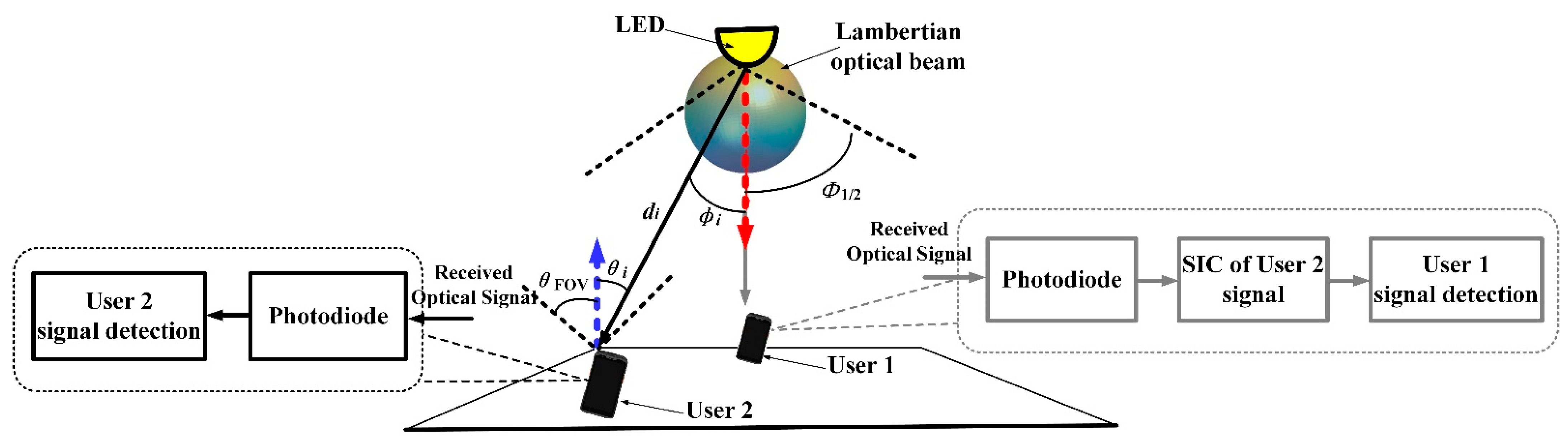
where is the semi-angle at half-illuminance of the Lambertian LED. When the Lambertian index is set as 1, the relevant 3D radiation pattern is as presented in Figure 1. Moreover, in this figure, the typical NOMA VLC indoor scenario with a single Lambertian emission beam is illustrated as well.
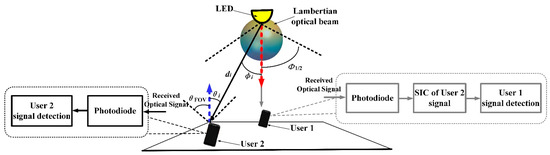
Figure 1.
Schematic of 6G NOMA VLC based on baseline Lambertian optical beam.
In this typical NOMA VLC indoor scenario, the proportion of the non-line-of-sight path component is much smaller than that of its counterpart, the line-of-sight propagation path component. For convenience of analysis, this article solely considers the contribution of the line-of-sight emission path. Accordingly, when the radiation characteristics of the optical source follow the Lambertian beam, the VLC channel gain at the receiver can be given as [24,26]
where is the detection area of the ith receiver; di denotes the distance between the light source or LED and the ith light receiver; is the irradiance angle from the light source to the ith receiver; denotes the incident angle to the ith receiver; and denotes the field of view (FOV) of the receiver. Moreover, denotes the gain of the light filter and denotes the gain of the light concentrator, given by [24,26]
where n is the refractive index of the light concentrator. By substituting (1) and (4) into (3), the baseline Lambertian light channel gain for NOMA VLC can be written as
For convenience of analysis, in this work, NOMA VLC is applied in a two-user scenario. The NOMA light transmitter processes the information of the two users in parallel and obtains the multicarrier signals and for user equipment 1 and user equipment 2. Then, the VLC transmitter applies superposition coding and forms the emitted electrical waveform as [10]
where N is the number of subcarriers, denotes the total available electrical power for the emitted signal, and is the electrical power splitting factor, which expresses the electrical power level to be distributed to the according information signal. In (6), and are normalized to one.
Consequently, the electrical signal at the receiver of kth user equipment, k 1, 2, can be written as
where denotes the responsivity, and denotes the additive white Gaussian noise term with zero mean and variance of .
As shown in (7), both users receive the signal for the other user, in addition to their own information signal. In the downlink NOMA VLC, the data signal for the far user, i.e., , is allocated more electrical power than the data signal for the near user, i.e., . In this way, the near user must first successfully decode and then apply successive interference cancellation (SIC) to recover its information signal .
For NOMA VLC adopting the baseline Lambertian optical beam configuration, assuming a frequency-flat optical channel, the respective achievable data rates for the NOMA VLC near user and the NOMA VLC far user could be separately written as [10]
where B denotes the baseband transmission bandwidth. It must be noted that the 1/2 terms in both (8) and (9) indicate the approximate spectral efficiency loss due to the Hermitian symmetry.
For VLC adopting the Lambertian optical beam configuration, the direct-current-biased orthogonal frequency division multiplexing (DCO-OFDM)-based orthogonal frequency division multiple access (OFDMA) is utilized as the benchmark for NOMA. In OFDMA, the VLC transmitter can control the VLC link throughput of each VLC user, through adjusting the allocated power and bandwidth among the users. Under this Lambertian OFDMA VLC scheme, the achievable data rates for the near VLC user and the far VLC user could be separately written as [10]
where and denote the allocation coefficients for the total available baseband transmission bandwidth and the total available electrical power, respectively. In other words, the near user occupies bandwidth and is allocated as the available electrical power, while the far user occupies bandwidth and is allocated as the available electrical power.
2.2. NOMA Visible Light Communications with Distinct Non-Lambertian Optical Beam Configuration
Unlike the well-discussed Lambertian light beam, the spatial radiation intensity of non-Lambertian emission beams provides distinct spatial selectivity for the emitted optical signal [25,26]. Without loss of generality, as typical non-Lambertian light beams, the counterparts from the LUXEON Rebel LED and the NSPW345CS Nichia LED are deliberately selected for the following discussion in this work. The argument for this adoption is that, on one hand, both emission beams possess quite different light radiation characteristics compared with the conventional Lambertian light beam; on the other hand, both non-Lambertian beams are generated by commercially available LEDs, which ensures that this system is applicable in a broad range of engineering applications.
Similar to the mentioned Lambertian light beam, the spatial radiation intensity of the light beam of the LUXEON Rebel LED or LED array conforms to rotational symmetry as well. Based on the popular measurement and modeling work on commercially available LED optical beams in [25], the spatial light radiation intensity of the LUXEON Rebel light beam can be characterized by the following equation as the sum of multiple Gaussian functions [25,26]:
where is the irradiance angle from the light source to the ith light receiver, and N1 = 2 is the number of Gaussian functions. More specifically, the values of the coefficients in this expression are = 0.76, = 0°, = 29°, = 1.10, = 45°, and = 21°. From the side view, Figure 2 illustrates the 3D emission beam patterns of the LUXEON Rebel non-Lambertian light beam with rotational symmetry. Unlike the above Lambertian light beam, in this non-Lambertian case, the maximum emission intensity does not appear in the normal emission direction, i.e., the red arrow direction, any longer, but at all directions with an irradiance angle of about 40°. Moreover, in this figure, a NOMA VLC indoor scenario with a single LUXEON Rebel light beam is illustrated as well.
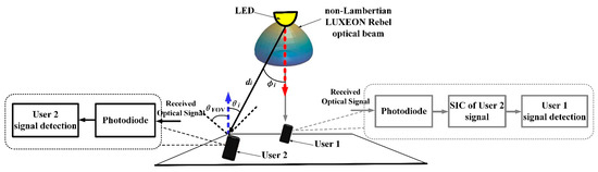
Figure 2.
Schematic of 6G NOMA VLC based on non-Lambertian LUXEON Rebel optical beam.
Similar to (3) and (5), the non-Lambertian LUXEON Rebel’s optical channel gain for NOMA VLC could be presented as
where is the power normalization factor of the LUXEON Rebel light beam, which functions to ensure that the light power radiated in all spatial directions is 1 W. In other words, unlike the conventional Lambertian light beam pattern, this non-Lambertian light beam pattern fails to achieve natural normalization, since it is derived from the numerical fitting of the measurement data based on a commercially available LED product.
Accordingly, the electrical data signal at the receiver of kth VLC user equipment, k 1,2, could be written as
where denotes the responsivity, and denotes the additive white Gaussian noise term with zero mean and variance of .
For NOMA VLC adopting the non-Lambertian LUXEON Rebel optical beam configuration, assuming a frequency-flat optical channel, the achievable data rates for the VLC near user and the VLC far user can be separately written as
For the VLC adopting the non-Lambertian LUXEON Rebel light beam configuration, direct-current-biased orthogonal frequency division multiplexing (DCO-OFDM)-based orthogonal frequency division multiple access (OFDMA) is also utilized as the benchmark for the above non-Lambertian LUXEON Rebel NOMA. In the non-Lambertian LUXEON OFDMA, the VLC transmitter could also control the VLC link throughputs of both users, through adjusting the power and bandwidth among both users. Under this non-Lambertian LUXEON OFDMA VLC scheme, the achievable data rates for the VLC near user and the VLC far user can be separately written as
where and still denote the allocation coefficients for the total transmission bandwidth and the total available electrical power, respectively.
Different from the well-known Lambertian light beam, the spatial radiation intensity of the asymmetric non-Lambertian light beam depends on the elevation and azimuth angle of the emitted light signal [25,26]. Without loss of generality, in the present study, an NSPW light beam is profiled and explored as an asymmetric non-Lambertian optical beam without spatial rotational symmetry to the non-Lambertian NOMA VLC link. Note that NSPW is not an abbreviation but a popular LED light beam model from an international LED manufacturer.
Under this light beam configuration, the respective spatial radiation intensity expression could be provided using the sum of multiple Gaussian functions [25,26]:
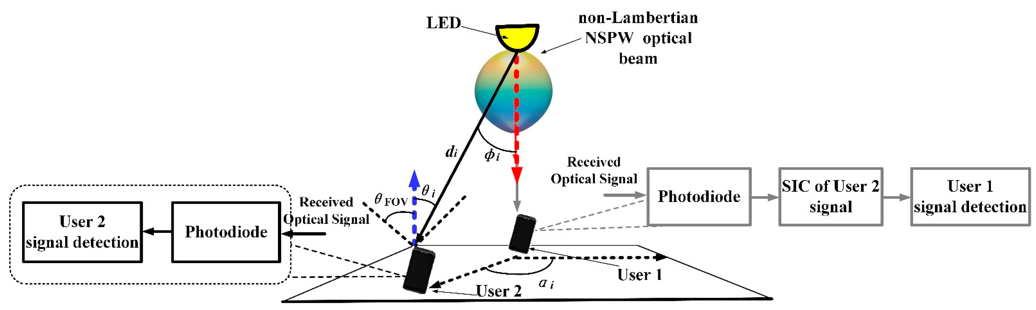
where is the azimuth angle from the light source to the ith light receiver, and the coefficient values of the Gaussian functions can be given as = 0.13, = 45°, = = 18°, = 1, = 0, = 38°, and = 22°. Similarly, the 3D display of the NSPW345CS UB emission beam is illustrated in Figure 3. Moreover, in this figure, a NOMA VLC indoor scenario with a single NSPW non-Lambertian light beam is illustrated as well.

Figure 3.
Schematic of 6G NOMA VLC based on asymmetric NSPW optical beam.
Similar to (3) and (5), the asymmetric non-Lambertian NSPW optical channel gain for NOMA VLC could be presented as
where is the power normalization factor of the NSPW light beam, which functions to ensure that the beam power emitted in all spatial directions is 1 W. In other words, unlike the conventional Lambertian beam pattern, this non-Lambertian light beam pattern also cannot realize natural normalization since it is derived from the numerical fitting of the measurement data based on a commercially available LED product.
Accordingly, the electrical signal at the receiver of kth user equipment, k 1,2, can be written as
where denotes the responsivity, and denotes the additive white Gaussian noise term with zero mean and variance of .
For NOMA VLC adopting the asymmetric non-Lambertian NSPW light beam configuration, assuming a frequency-flat light channel, the achievable data rates for the VLC near user and the VLC far user can be separately written as
For the VLC adopting the asymmetric non-Lambertian NSPW optical beam configuration, direct-current-biased orthogonal frequency division multiplexing (DCO-OFDM)-based orthogonal frequency division multiple access (OFDMA) is also utilized as the benchmark for the above asymmetric non-Lambertian NSPW Rebel NOMA. In the asymmetric non-Lambertian NSPW OFDMA, the VLC transmitter can also control the VLC link throughputs of both users, through adjusting the power and bandwidth among both users. Under this asymmetric non-Lambertian NSPW OFDMA VLC scheme, the achievable data rates for the VLC near user and the VLC far user can be separately written as
where and also denote the allocation coefficients for the total transmission bandwidth and the total available electrical power, respectively.
3. Numerical Evaluation
In this section, a performance comparison is accomplished between the NOMA VLC system employing the classical Lambertian emission beam configuration and the NOMA VLC system employing an emerging non-Lambertian emission beam configuration in a typical indoor environment. More specifically, one typical medium-sized room, i.e., 5 m × 5 m × 3 m, is envisioned, which is popular and consistent with most publications in the VLC domain. Additionally, the key simulation parameters considered are provided in Table 1; these are mainly adopted from the reported work in reference [10]. The data in the following Figure 4, Figure 5 and Figure 6 are all obtained by simulations in the MATLAB environment. However, it should be noted that the MATLAB tool is not essential for the numerical study of NOMA VLC with distinct optical beam configurations, and other numerical analysis tools, including the popular Python, which is free of charge, could be utilized to complete this simulation evaluation process.

Table 1.
Main parameter configuration.
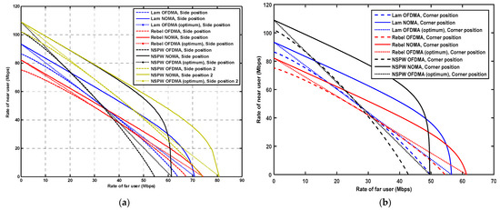
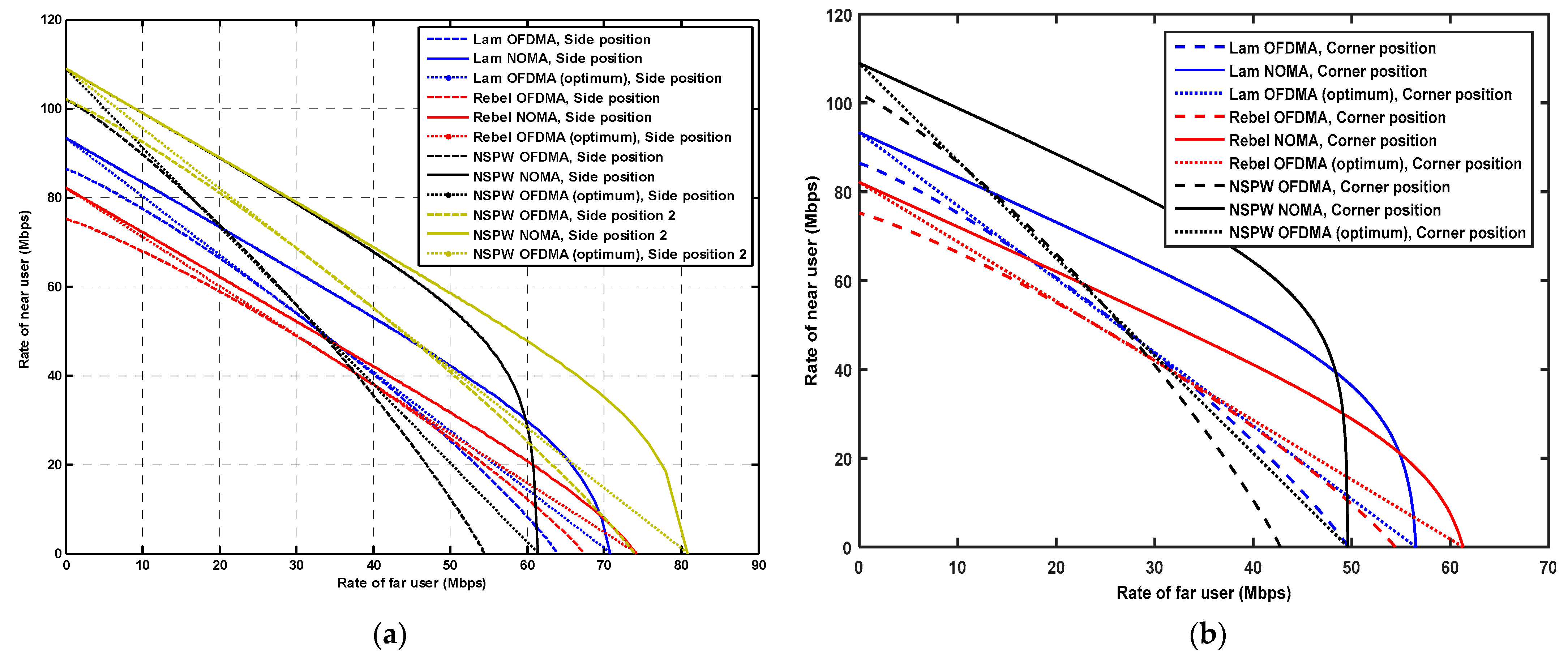
Figure 4.
Comparison of performance boundary of 6G NOMA VLC rate pairs with distinct optical beam configuration: (a) far user located at the side position and (b) far user located at the corner position.
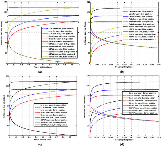
Figure 5.
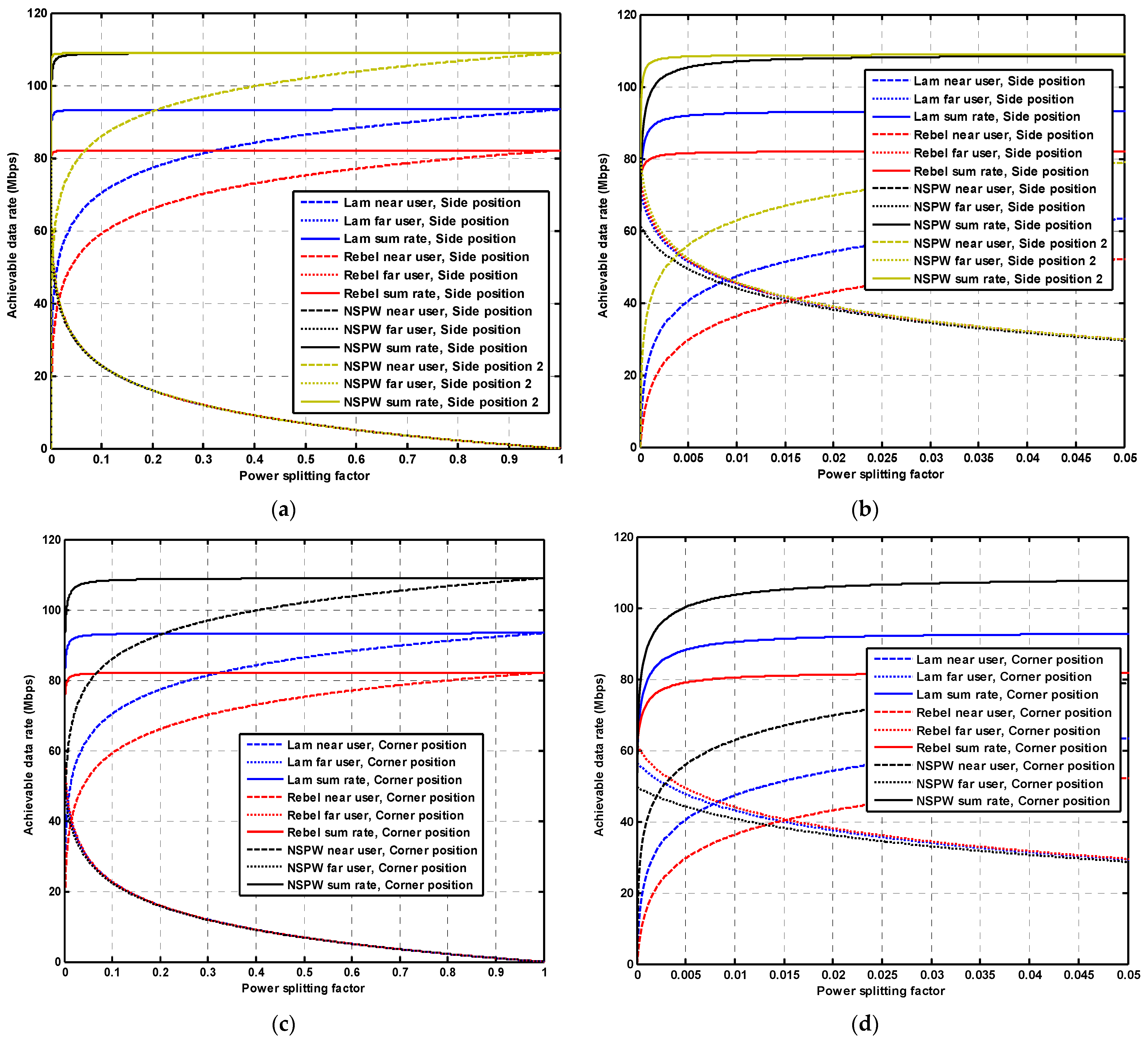
Comparison of achievable data rate versus power splitting factor for 6G NOMA VLC with distinct optical beam configuration: (a) far user located at the side position, (b) locally zoomed-in results for the case of the far user located at the side position and (c) the far user located at the corner position, and (d) locally zoomed-in results for the case of the far user located at the corner position.
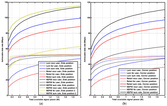
Figure 6.
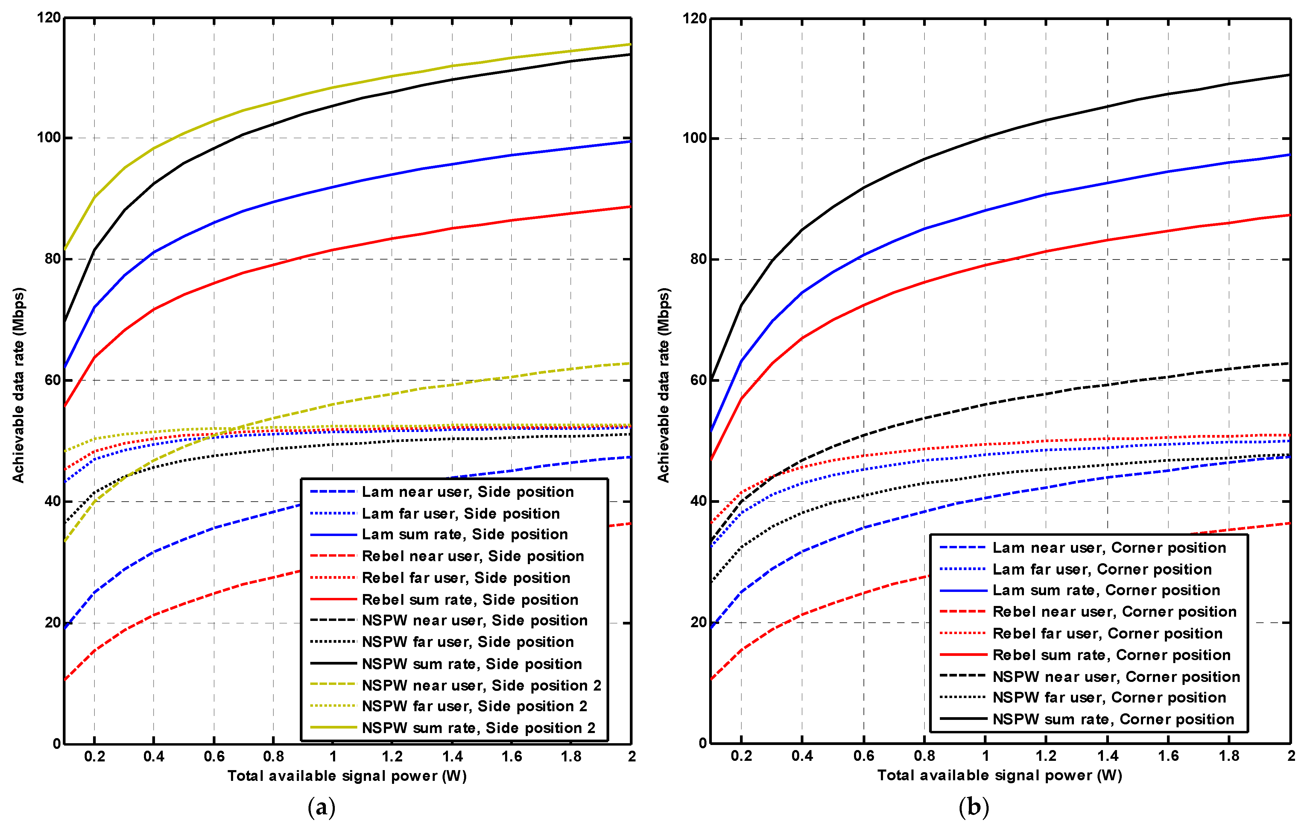
Comparison of achievable data rate versus total available signal power for 6G NOMA VLC with distinct optical beam configuration: (a) far user located at the side position and (b) far user located at the corner position.
For convenience of analysis, the location of one corner of the ground is set at (0, 0, 0) m, i.e., the origin of the coordinates. Accordingly, the location of the near user is set at (2.5, 2.5, 0.7) m, i.e., the center position of the receiver’s working plane, to obtain better light channel conditions for VLC. As for the far user, without loss of generality, one representative side position, i.e., (2.5, 0.5, 0.7) m, and one representative corner position, i.e., (0.5, 0.5, 0.7) m, are chosen as the candidate locations to provide more challenging light channel conditions. Considering the rotational asymmetry of the concerned non-Lambertian NSPW beam configuration in terms of spatial radiation, as shown in Figure 3, one additional candidate side location, i.e., (0.5, 2.5, 0.7) m, which is next to the previous side position, should be introduced for the present investigation related to the NSPW beam configuration. For clarity, the normal direction of the LED optical source points vertically down towards the ground, whereas that of the receivers points vertically up to the ceiling, regardless the location of the communication user.
3.1. Comparison of Capacity Region Performance
In this subsection, the achievable rate regions for NOMA VLC and OFDMA VLC employing distinct emission beam configurations are compared. Firstly, when the far user is located at the side position, the performance boundaries of the 6G NOMA VLC rate pairs are as demonstrated in Figure 4a. Specifically, for the Lambertian light beam configuration, without loss of generality, in the original OFDMA VLC case, the total available signal power is equally allocated between the VLC near user and the VLC far user, which means that the OFDMA signal power allocation coefficient = 0.5, and the blue dashed line denotes varying bandwidth allocation coefficients . Moreover, following the work of reference [10], once the joint optimization of and is applied, the optimum OFDMA VLC capacity could be achieved, as described by the blue dotted line in Figure 4a. Unlike the case of OFDMA VLC, the achievable rate region of NOMA VLC is obtained and described by merely varying the electrical power splitting factor , which is plotted by the blue solid line. It can be observed that, for the case of the Lambertian emission beam configuration, the optimum OFDMA VLC capacity region is almost always superior to that of the original OFDMA VLC, thanks to the more flexible transmission resource distribution.
At the same time, the obvious capacity region gain can be achieved by applying NOMA in VLC with the Lambertian optical beam configuration. In particular, when the near user rate is fixed at 60 Mbps, the far user rate for the OFDMA, optimum OFDMA, and NOMA is 25.2 Mbps, 25.3 Mbps, and 33.2 Mbps, respectively. This indicates that an achievable gain of up to about 8.0 Mbps could be provided by NOMA, compared to the benchmark original OFDMA, in the Lambertian situation. In contrast, in the situation of the non-Lambertian LUXEON Rebel light beam configuration, the achievable gain for the NOMA solution is comparatively limited, as shown by the red lines in Figure 4a. Specifically, when the near user rate is fixed at 60 Mbps, the far user rate is 18.8 Mbps, 20.0 Mbps, and 22.1 Mbps, respectively, for the OFDMA, optimum OFDMA, and NOMA, which means that the achievable gain is just 3.3 Mbps when employing NOMA. This phenomenon is mainly due to the fact that the maximum radiation intensity does not appear in the normal direction of the LED source any longer, and more optical power is emitted to the surrounding area, which further results in a reduction in the channel quality difference between the VLC near user and the VLC far user. In contrast, in the situation of the non-Lambertian NSPW beam configuration, the achievable gain for the NOMA solution is impressive, as shown by the black lines in Figure 4a. Similarly, with the near user rate of 60 Mbps, the far user rate is 27.7 Mbps, 27.5 Mbps, and 46.5 Mbps, respectively, for the OFDMA, optimum OFDMA, and NOMA, which means that a data rate gain of up to about 19 Mbps could be achieved by utilizing NOMA under the NSPW emission beam configuration. As mentioned above, considering the rotational asymmetry of the NSPW beam configuration, the performance for the far user at the additional side, i.e., (0.5, 2.5, 0.7) m, must be studied to provide sufficient numerical observation. Thanks to the further enlarged visible light channel quality difference between the near user and the VLC far user, the attainable data rate gain is further varied to about 12.3 Mbps, with the VLC near user rate of 60 Mbps. In particular, the respective far user rate is 36.4 Mbps, 36.3 Mbps, and 48.7 Mbps, respectively, for the OFDMA, optimum OFDMA, and NOMA, as shown by the yellow lines in Figure 4a.
Secondly, when the far user is located at the more challenging corner position, similar performance boundaries for the 6G NOMA VLC rate pairs are demonstrated, as shown in Figure 4b. Typically, for the Lambertian situation, once the near user rate is fixed at 60 Mbps, the realized far user rate is 20.4 Mbps, 20.2 Mbps, and 32.5 Mbps for the OFDMA, optimum OFDMA, and NOMA, respectively. Meanwhile, for the non-Lambertian LUXEON Rebel situation, the achieved far user rate is 15.8 Mbps, 16.5 Mbps, and 22.0 Mbps for the mentioned three multiple access solutions, respectively, while these performance metrics become 22.5 Mbps, 22.3 Mbps, and 42.4 Mbps once the non-Lambertian NSPW beam configuration is employed. It could be identified that, even for the most challenging corner position, the attainable data rate gain when applying the NOMA VLC solution is up to 12.1 Mbps, 6.2 Mbps, and 19.9 Mbps for the Lambertian, non-Lambertian Rebel, and non-Lambertian NSPW beam configurations, compared with the original OFDMA VLC solution.
3.2. Effect of Power Splitting Factor
In this subsection, the achievable data rate versus power splitting factor for NOMA VLC and OFDMA VLC when employing distinct emission beam configurations is compared. Specifically, as given in Figure 5a, when the VLC far user is located at the side position, it could be observed that the rate of the near user rapidly increases and the rate of the far user rapidly decreases when the power splitting factor is increased from 0 to 0.1, regardless of the applied optical beam configuration. Furthermore, when the power splitting factor is increased from 0.1 to 1, the far user rate is slowly reduced to 0 Mbps, while the near user rate is slowly increased to the maximum data rate, i.e., the sum rate of both VLC users. A the same time, it could be observed that when the power splitting factor is increased from 0 to 0.1, the sum rates of both VLC users rapidly reach a saturation state, which means that a further increase in the power splitting factor will not contribute to the sum rate any longer, but the data rate allocation between the concerned two users will be adjusted. The saturation level is about 93 Mbps, 82 Mbps, and 108 Mbp for the Lambertian, LUXEON Rebel, and non-Lambertian NSPW light beam configurations, respectively, which indicates that the final saturation level performance of the sum rate is dominated by the superiority of the channel quality of the near users, to a large extent.
For the sake of clarity, a locally enlarged version of Figure 5a is presented in Figure 5b. It demonstrates that the maximum sum rate for the Lambertian situation at the side position, the LUXEON Rebel at the side position, the non-Lambertian NSPW beam at the side position, and the non-Lambertian NSPW beam at side position 2 is about 93.33 Mbps, 82.12 Mbps, 108.92 Mbps, and 108.92 Mbps, respectively, which means that a NOMA VLC sum rate gain of up to about 15.6 Mbps could be obtained by the non-Lambertian NSPW beam configuration at the two concerned side positions compared to the conventional Lambertian light beam configuration. From the perspective of the data rate fairness of both users, the rate with approximately optimal fairness, i.e., = , is about 46.2 Mbps, 41.0 Mbps, 52 Mbps, and 54 Mbps for the Lambertian situation at the side position, the LUXEON Rebel at the side position, the non-Lambertian NSPW beam at the side position, and the non-Lambertian NSPW beam at side position 2, which indicates that the non-Lambertian NSPW beam could provide an approximately 7.8 Mbps gain with the optimal rate fairness of both users.
Similarly, for the more challenging corner position, the final saturation level is about 93.3 Mbps, 82.1 Mbps, and 108.92 Mbp for the Lambertian, LUXEON Rebel, and non-Lambertian NSPW light beam configurations, respectively, as shown in Figure 5c,d. In terms of data rate fairness, the rate with approximately optimal fairness is about 44.9 Mbps, 40.5 Mbps, and 54 Mbps for the concerned three light beam configurations of NOMA VLC, which indicates that the channel condition difference between both users for the rate gain is mitigated compared with that of the above-mentioned side position and side position 2.
3.3. Effect of Total Available Signal Power
In this subsection, the achievable data rate versus total available signal power for NOMA VLC and OFDMA VLC when employing distinct beam configurations is comparatively investigated, as shown in Figure 6. Based on the illustrative results in the above subsection, to ensure sufficient data rate fairness, the power splitting factor is set as 0.005 in this subsection.
On one hand, for the case of the side position, as given in Figure 6a, when the initial total available signal power is set as 0.1 W, the sum rate is about 62.1 Mbps, 55.6 Mbps, 69.7 Mbps, and 81.5 Mbp for the Lambertian situation at the side position, the LUXEON Rebel at the side position, the non-Lambertian NSPW beam at the side position, and the non-Lambertian NSPW beam at side position 2, while the counterparts are separately increased to about 99.6 Mbps, 88.7 Mbps, 113.9 Mbps, and 115.6 Mbps as the total available signal power is enhanced to 2 W. This indicates that, compared with the performance of the benchmark Lambertian beam configuration, the sum rate gain provided by the non-Lambertian NSPW light beam is varied to 14.3 Mbps and 16 Mbps for the side position and side position 2 from the initial values of about 7.6 Mbps and 19.4 Mbps. At the same time, it could be observed that, when the total available signal power is more than about 1 W, the rates of the far user become close to saturation with a level of about 50 Mbps, regardless of the specific beam configuration, which means that the following sum rate increase is mainly contributed by the signal power captured by the near user with the better light channel conditions. Note that, under the non-Lambertian NSPW light beam configuration, the rate of 44 Mbps with optimal fairness could be reached as the total available signal power is enhanced to about 0.3 W for the side position, while the rate of 52.1 Mbps with optimal fairness could be reached when the total signal power is set at about 0.7 W for side position 2. At the same time, even when the total signal power is increased further to 2 W, the rate with optimal fairness still could not be achieved by the left Lambertian and non-Lambertian LUXEON Rebel light beam configurations, due to the lack of a sufficient light channel quality difference between the two users.
Similarly, as given in Figure 6b, for the corner position, when the initial total available power is applied, the sum rate is about 51.4 Mbps, 46.9 Mbps, and 59.8 Mbp for the three beam configurations, while their counterparts are separately increased to about 97.4 Mbps, 87.4 Mbps, and 110.6 Mbps as the total power is enhanced to 2 W. This indicates that the sum rate gain provided by the non-Lambertian NSPW light beam is varied to 13.2 Mbps from the initial value of about 8.4 Mbps compared with the performance of the benchmark Lambertian light beam configuration.
4. Discussion of Contributions
Apparently, although the same Lambertian and non-Lambertian beams are considered in this work and in reference [27], they are applied and explored in entirely different branch domains of visible light communication. Specifically, the investigated branch domain of this work is the multiple access technology of visible light communications, while the counterpart in the mentioned work in [27] is the simultaneous light wave information and power transfer of visible light communications. Moreover, note that there is a fundamental difference in the system’s mathematical description between the above-mentioned two works. The key contributions of this work are summarized as follows: the mathematical descriptions and system models of the NOMA VLC scheme based on distinct non-Lambertian beams are provided for the first time, and the fundamental performance metrics are comparatively evaluated between the baseline Lambertian NOMA VLC scheme and the proposed non-Lambertian NOMA VLC schemes. Furthermore, the capacity region performance and the effects of the power splitting factor and the total available signal power are numerically investigated for the concerned NOMA VLC schemes with distinct light beam configurations.
5. Conclusions
This work was motivated by the limitations of the conventional Lambertian optical beam-based NOMA VLC technique paradigm, which is not applicable to potential NOMA VLC scenarios with distinct non-Lambertian optical beam configurations. In this work, the distinct beam pattern of commercially available non-Lambertian optical sources is utilized to configure NOMA VLC transmission links. For the case of the far user, i.e., UE2 located at the side receiver position, an up to 7.8 Mbps gain with the optimal rate fairness of both users could be derived with the proposed non-Lambertian NOMA VLC beam configuration, while the counterpart for the benchmark Lambertian NOMA VLC configuration is about 46.2 Mbps. In the future work on 6G mobile networks, the exploration of distinct non-Lambertian optical beam configurations based on NOMA VLC could be further extended to customized beam steering, beam cooperation, dynamic beam configurations, beam switching, resource allocation, reconfigurable multiple-input multiple-output schemes, and other enabling techniques. The development of a more sophisticated power allocation strategy, which usually concerns user fairness and system efficiency, is a vital and well-known study topic in the field of conventional Lambertian beam-based NOMA VLC, and a great number of works related to this topic have been consistently reported thus far. However, it deserves a series of independent investigations and discussions regarding this novel and promising domain of non-Lambertian beam-based NOMA VLC in the near future.
Author Contributions
J.D. determined the theme and structure of the article, provided professional knowledge in the field of visible light communications, wrote and modified the article, and replied to comments from the editors and reviewers. C.-L.I. provided theoretical knowledge of mobile communication and wireless communication. J.W. searched the literature and participated in the discussion and the writing of some of the content. H.Y. searched the literature and participated in the discussion. All authors have read and agreed to the published version of the manuscript.
Funding
This work was supported in part by the National Natural Science Foundation of China (Grant No. 62061043), the Tianshan Cedar Project of Xinjiang Uygur Autonomous Region (Grant No. 2020XS27), the and High-Level Talents Introduction Project in the Autonomous Region (Grant No. 042419004).
Institutional Review Board Statement
Not applicable.
Informed Consent Statement
Not applicable.
Data Availability Statement
Data are contained within the article.
Conflicts of Interest
The authors declare no conflicts of interest.
References
- Zhang, Y.; Zhang, H.; Cosmas, J.; Jawad, N.; Ali, K.; Meunier, B.; Zarakovitis, C.C. Internet of radio and light: 5G building network radio and edge architecture. Intell. Converg. Netw. 2020, 1, 37–57. [Google Scholar] [CrossRef]
- Chowdhury, M.Z.; Hossan, M.T.; Islam, A.; Jang, Y.M. A comparative survey of optical wireless technologies: Architectures and applications. IEEE Access 2018, 6, 9819–9840. [Google Scholar] [CrossRef]
- Sun, S.; Yang, F.; Song, J. Sum rate maximization for intelligent reflecting surface-aided visible light communications. IEEE Commun. Lett. 2021, 25, 3619–3623. [Google Scholar] [CrossRef]
- Sun, S.; Wang, T.; Yang, F.; Song, J.; Han, Z. Intelligent reflecting surface-aided visible light communications: Potentials and challenges. IEEE Veh. Technol. Mag. 2022, 17, 47–56. [Google Scholar] [CrossRef]
- Wang, T.; Yang, F.; Song, J.; Han, Z. Dimming Techniques of Visible Light Communications for Human-Centric Illumination Networks: State-of-the-Art, Challenges, and Trends. IEEE Wirel. Commun. 2020, 27, 88–95. [Google Scholar] [CrossRef]
- Ding, J.; I, C.-L.; Wang, J.; Song, J. Coverage Performance of Non-Lambertian Underwater Wireless Optical Communications for 6G Internet of Things. Inventions 2024, 9, 49. [Google Scholar] [CrossRef]
- Hamza, A.S.; Deogun, J.S.; Alexander, D.R. Classification framework for free space optical communication links and systems. IEEE Commun. Surv. Tuts. 2019, 21, 1346–1382. [Google Scholar] [CrossRef]
- Higuchi, K.; Benjebbour, A. Non-orthogonal Multiple Access (NOMA) with Successive Interference Cancellation for Future Radio Access. IEICE Trans. Commun. 2015, 3, 403–414. [Google Scholar] [CrossRef]
- Bawazir, S.; Sofotasios, P.; Muhaidat, S.; Al-Hammadi, Y.; Karagiannidis, G. Multiple Access for Visible Light Communications: Research Challenges and Future Trends. IEEE Access 2018, 6, 26167–26174. [Google Scholar] [CrossRef]
- Kizilirmak, R.; Rowell, C.; Uysal, M. Non-orthogonal multiple access (NOMA) for indoor visible light communications. In Proceedings of the 2015 4th International Workshop on Optical Wireless Communications (IWOW), Istanbul, Turkey, 7–8 September 2015; IEEE: New York, NY, USA, 2015. [Google Scholar]
- Rajput, V.; Ashok, D.; Chockalingam, A. Joint NOMA Transmission in Indoor Multi-cell VLC Networks. In Proceedings of the 2019 IEEE 30th Annual International Symposium on Personal, Indoor and Mobile Radio Communications (PIMRC), Istanbul, Turkey, 8–11 September 2019; IEEE: New York, NY, USA, 2019. [Google Scholar]
- Raj, R.; Dixit, A. An Energy-Efficient Power Allocation Scheme for NOMA-Based IoT Sensor Networks in 6G. IEEE Sens. J. 2022, 22, 7371–7384. [Google Scholar] [CrossRef]
- Alhammadi, A.; Bariah, L.; Muhaidat, S.; Alqutayri, M.; Sofotasios, P.C.; Debbah, M. Deep Q-Learning-based Resource Allocation in NOMA Visible Light Communications. IEEE Open J. Commun. Soc. 2022, 3, 2284–2297. [Google Scholar] [CrossRef]
- Raj, R.; Jindal, K.; Dixit, A. Fairness Enhancement of Non-Orthogonal Multiple Access in VLC-Based IoT Networks for Intravehicular Applications. IEEE Trans. Veh. Technol. 2022, 71, 7414–7427. [Google Scholar] [CrossRef]
- Tennakoon, P.; Rajkumar, S.; Jayakody, D. Game Theory Based Delta-OMA Scheme for VLC Network. IEEE Access 2023, 50, 10777–10791. [Google Scholar] [CrossRef]
- Uday, T.; Kumar, A.; Natarajan, L. Joint NOMA for Improved ser of Cell-Edge Users in Multi-Cell Indoor VLC. IEEE Wirel. Commun. Lett. 2022, 11, 13–17. [Google Scholar] [CrossRef]
- Chen, C.; Zhong, W.; Yang, H.; Du, P. On the Performance of MIMO-NOMA Based Visible Light Communication Systems. IEEE Photonics Technol. Lett. 2018, 11, 307–310. [Google Scholar] [CrossRef]
- Cang, Y.; Chen, M.; Zhao, J.; Yang, Z.; Huang, C.; Gong, T.; Zhang, Z. Optimal Resource Management for NOMA-Based Visible Light Communication Systems with Shot Noise. IEEE Trans. Green Commun. Netw. 2022, 6, 2015–2031. [Google Scholar] [CrossRef]
- Zhu, M.; Wang, Y.; Liu, X.; Ma, S.; Zhang, X.; Fu, Y. Performance Analysis for DF Relay-aided Visible Light Communication System with NOMA. IEEE Photonics J. 2022, 6, 7350809. [Google Scholar] [CrossRef]
- Tran, M.; Vu, T.; Kim, S. Performance Analysis of Optical Backhauled Cooperative NOMA Visible Light Communication. IEEE Trans. Veh. Technol. 2021, 70, 12932–12945. [Google Scholar] [CrossRef]
- Tran, G.; Kim, S. Performance Analysis of Short Packets in NOMA VLC Systems. IEEE Access 2022, 10, 6505–6517. [Google Scholar] [CrossRef]
- Li, G.; Wang, P.; Yang, T.; Che, H. Secrecy Sum-Rate Enhancement for NOMA-VLC System with Pseudo User. IEEE Commun. Lett. 2023, 27, 243–247. [Google Scholar] [CrossRef]
- Shi, G.; Aboagye, S.; Ngatched, T.; Dobre, O.; Li, Y.; Cheng, W. Secure Transmission in NOMA-Aided Multiuser Visible Light Communication Broadcasting Network with Cooperative Precoding Design. IEEE Trans. Inf. Forensics Secur. 2022, 17, 3123–3138. [Google Scholar] [CrossRef]
- Komine, T.; Nakagawa, M. Fundamental analysis for visible-light communication system using LED lights. IEEE Trans. Consum. Electron. 2004, 50, 100–107. [Google Scholar] [CrossRef]
- Moreno, I.; Sun, C.-C. Modeling the radiation pattern of LEDs. Opt. Exp. 2008, 16, 1808–1819. [Google Scholar] [CrossRef] [PubMed]
- Ding, J.; Chih-Lin, I.; Xu, Z. Indoor optical wireless channel characteristics with distinct source radiation patterns. IEEE Photonics J. 2016, 8, 7900115. [Google Scholar] [CrossRef]
- Ding, J.; I, C.-L.; Wang, J.; Song, J. Performance Evaluation of Non-Lambertian SLIPT for 6G Visible Light Communication Systems. Photonics 2024, 11, 856. [Google Scholar] [CrossRef]

Disclaimer/Publisher’s Note: The statements, opinions and data contained in all publications are solely those of the individual author(s) and contributor(s) and not of MDPI and/or the editor(s). MDPI and/or the editor(s) disclaim responsibility for any injury to people or property resulting from any ideas, methods, instructions or products referred to in the content. |
© 2024 by the authors. Licensee MDPI, Basel, Switzerland. This article is an open access article distributed under the terms and conditions of the Creative Commons Attribution (CC BY) license (https://creativecommons.org/licenses/by/4.0/).