Article

Wavelength Locking and Calibration of Fiber-Optic Ultrasonic Sensors Using Single-Sideband-Modulated Laser

Department of Electrical and Computer Engineering, Michigan State University, East Lansing, MI 48823, USA
*
Author to whom correspondence should be addressed.
Photonics 2024, 11(11), 1063; https://doi.org/10.3390/photonics11111063
Submission received: 21 October 2024 / Revised: 8 November 2024 / Accepted: 9 November 2024 / Published: 13 November 2024
(This article belongs to the Special Issue Recent Research on Optical Sensing and Precision Measurement)

Abstract

:
Implementation of edge-filter detection for interrogating optical interferometric ultrasonic sensors is often hindered by the lack of cost-effective laser sources with agile wavelength tunability and good noise performance. The detected signal can also be affected by optical power variations and locking-point drift, negatively affecting the sensor accuracy. Here, we report the use of laser single-sideband generation with a dual-parallel Mach–Zehnder interferometer (DP-MZI) for laser wavelength tuning and locking in edge-filter detection of fiber-optic ultrasonic sensors. We also demonstrate real-time in situ calibration of the sensor response to ultrasound-induced wavelength shift tuning. The DP-MZI is employed to generate a known wavelength modulation of the laser, whose response is used to gauge the sensor response to the ultrasound-induced wavelength shifts in real time and in situ. Experiments were performed on a fiber-optic ultrasonic sensor based on a high-finesse Fabry–Perot interferometer formed by two fiber Bragg gratings. The results demonstrated the effectiveness of the laser locking against laser wavelength drift and temperature variations and the effectiveness of the calibration method against optical power variations and locking-point drift. These techniques can enhance the operational robustness and increase the measurement accuracy of optical ultrasonic sensors.

1. Introduction

Fiber-optic ultrasonic sensors have emerged as a promising technology for ultrasound measurement in various applications such as structural health monitoring, non-destructive testing, and photoacoustic imaging [1,2]. Compared with piezoelectric sensors, fiber-optic sensors have the advantages of small size, light weight, low transmission loss, immunity to electromagnetic interference, and resistance to harsh conditions. Resolution and accuracy are two important parameters of ultrasonic sensors. Resolution is determined by both the sensitivity and the noise performance of the sensor system. Higher resolution can be achieved by increasing the sensitivity and/or reducing the noise of the system. One of the most effective means to increase the sensitivity of fiber-optic ultrasonic sensors is to use high-Q resonators, such as π-phase-shifted fiber Bragg gratings (FBGs), fiber in-line Fabry–Perot (FP) interferometers formed by two high-reflection FBGs, and micro-ring resonators [3,4,5,6]. These interferometric sensors have very narrow features with large spectral slopes in their reflection or transmission spectrum and are typically interrogated by the edge-filter method where a laser line is set in the linear range of the spectral slope to convert the ultrasound-induced wavelength shift into laser intensity variations to be measured by a photodetector [7,8]. In practical applications, a significant challenge facing edge-filter detection is environmental perturbations to the sensors. For example, ambient temperature variations and strains from loading can cause large shifts of the sensor spectrum and knock the laser line out of the linear range. Because of these large environmental spectral shifts, edge-filter detection requires a wavelength-tunable laser with a tuning range that can cover the spectral shift along with a feedback control scheme to lock the laser to most sensitive position on the spectral slope. Additionally, as the sensor’s spectral features become increasingly narrow for improved detection sensitivity, the laser wavelength tuning needs to have sufficient precision and agility to ensure robust locking on a narrow spectral notch or peak with a small linear range. An effective method to alleviate the issues caused by mechanical strain is remote bonding [9,10,11], in which the bonding point of the sensor is at a distance from the FBG region and the ultrasound is coupled to the fiber at the bonding point, then travels along the fiber as a guided acoustic wave to the FBG’s sensitive region for detection. However, remote bonding cannot reduce the spectral shift caused by ambient temperature variations. Another demodulation method to counter the environmental perturbations is based on two-wave mixing in photorefractive crystals [12,13]. This method uses a broadband light source to demodulate ultrasonic sensors based on regular FBGs, which is not suitable for high-finesse FBG-FPI sensors and typically has lower noise performance.
Driven by the need for coherent fiber-optic communication, recent technical advancement has made small, low-noise, and low-cost semiconductor lasers available on the market. They often also possess a wide (albeit slow) tuning capability that makes them useful in a multiplexed sensor system using wavelength-division multiplexing. Such lasers often have an external-cavity configuration to reduce the frequency noise, yielding a laser linewidth < 100 kHz. Wide and coarse wavelength tuning over a range of tens of nm can be achieved using the Vernier effect with laser mirrors that have comb-like reflection characteristics with a small difference in the comb pitches between the two mirrors [14,15,16]. Lasing occurs at the wavelength where two comb fingers overlap. A small shift in one mirror’s spectrum can cause large changes in the wavelength of aligned comb fingers, resulting in large laser wavelength tuning. Wavelength tuning is discontinuous and rather coarse in this method. Fine tuning is needed to set the laser to a precise wavelength, which is achieved thermally using a temperature controller to avoid the degradation of the laser frequency noise from the control electronics. However, thermal control is a relatively slow process and lacks the agility needed in the edge-filter demodulation of fiber-optic ultrasonic sensors.
Another issue common to fiber-optic interferometric ultrasonic sensor systems is the measurement error caused by optical power changes, as the output of the sensor system is proportional to the optical power. The changes can come from power drift of the laser sources or from perturbations to the fiber and other components in the optical paths. For edge-filter detection with feedback controls, optical power changes can affect the signal in an additional way. The control signal is usually the optical power reflected from the sensor. Optical power changes will change the operating point on the sensor spectrum and consequently change the slope at the operating point and the sensitivity of the sensor. Recently, we have proposed and demonstrated a method to calibrate the signal against the ultrasound-induced wavelength shift for a low-finesse fiber-optic FP ultrasonic sensor [17]. The method is only applicable to sensors demodulated using the phase-generated carrier (PGC) scheme, where the carrier signal is generated from a phase modulator. However, the PGC method requires the sensor to have sinusoidal fringes and cannot be used for demodulating high-finesse fiber-optic ultrasonic sensors. Research for calibration of fiber-optic ultrasonic sensors demodulated with edge-filter detection has not been reported.
In this paper, we demonstrate the use of laser single-sideband generation using a dual-parallel Mach–Zehnder interferometer (DP-MZI) [18,19] to achieve the required precision and agility of laser wavelength tuning for laser wavelength locking in edge-filter detection of high-Q fiber-optic interferometric ultrasonic sensors. Wavelength tuning of the single sideband is achieved by changing the frequency of the RF signal driving the DP-MZI through a voltage-controlled oscillator (VCO). In addition, we demonstrate a real-time in situ calibration method using the same DP-MZI and VCO to provide wavelength modulation of a laser with known modulation amplitude. The response of the sensor system to this laser wavelength modulation is used to gauge the response to the ultrasound-induced wavelength shift of the sensor and remove the measurement errors caused by optical power changes and operating-point drift.

2. Principle of Operation

2.1. Sideband Locking for Edge-Filter Detection

Figure 1 shows a schematic of the fiber-optic ultrasonic sensor system. As an example, and to be consistent with the laser used in the experiment, we assume that the sensor is a high-finesse FP formed by two FBGs, and one of its narrow reflection notches (see the inset of Figure 1) is used for ultrasonic detection. The light source is a low-noise, tunable laser with a relatively slow tuning speed. The laser from the light source is injected into a single-sideband generation module consisting of a DP-MZI, a VCO, and a DC bias unit. A more detailed diagram of the single-sideband generation unit is shown in Figure 1b. The output from the DP-MZI is a laser line whose frequency is shifted from the original laser line by the RF signal from the VCO, as shown in Figure 1c. Adjusting the voltage of the VCO will tune the laser frequency in the range corresponding to the frequency range of the VCO. The quasi-DC component of the output of the photodetector, which detects the light reflected from the sensor, contains the information of the operating point, which is filtered out and used to lock the sideband to the slope of the sensor reflection spectrum. Combining the inherent wavelength tuning mechanism of the laser in the agile tuning from the DP-MZI will provide the ability to precisely lock the laser line to the desired position of the narrow spectral notches of the sensor over a large spectral range.
A brief description of the operation of the single-sideband generation module is provided here. As shown in Figure 1b, the main component is a DP-MZI integrated in a single x-cut LiNbO3 crystal [18,19]. Each of the MZIs can be modulated by an oscillation at RF frequency Ω , and DC biases are applied to the device to control the phase delay between the two arms of each MZI as well as the phase delay between the two MZIs. For single-sideband generation, the RF signals injected to the two MZIs are 90° out of phase, the phase delay between the two arms of each MZI is set to π, and the phase delay between the two MZIs is set to π/2. The electrical field from the tunable laser is expressed as E t = e j ω 0 t , where ω 0 is the angular frequency of the laser, t denotes time, and j is the imaginary unit. The modulation signals to the upper and lower MZIs are, respectively, Ω m cos Ω t and Ω m sin Ω t , where Ω and Ω m are, respectively, the angular frequency of the RF modulation and the modulation depth. Then, the output from the DP-MZI can be expressed as
E t = 1 2 e j ω 0 t e j Ω m cos Ω t e j Ω m cos Ω t + j e j Ω m sin Ω t e j Ω m sin Ω t
Applying the Jacobi–Anger expansion for the exponentials of the sine and cosine functions, we can re-write Equation (1) as
E t = j k = + 1 + 1 k J 2 k + 1 Ω m e j ω 0 + 2 k + 1 Ω t ,
where J k denotes the k t h -order Bessel function of the first kind. Equation (2) indicates that the output from the DP-MZI contains a series of sidebands without the original laser line. These sidebands are separated by 4 Ω , with most of the laser power distributed among the first few of them, denoted as [20].
fundamental   ( k = 0 ) : A J 1 Ω m e j ω 0 + Ω t 3 rd   order   ( k = 2 ) : A J 3 Ω m e j ω 0 3 Ω t 5 th   order   ( k = 2 ) : A J 5 Ω m e j ω 0 + 5 Ω t
where A is the complex amplitude of the light. It is seen that, by adjusting the modulation depth, Ω m , the fundamental sideband can be made dominant, resulting in the generation of a single sideband at ω 0 + Ω . Using a wideband VCO to provide the RF driving signal, the frequency of the sideband can be continuously tuned over a wide frequency range at high speed (the modulation bandwidth of VCOs can reach tens of MHz).

2.2. Real-Time In Situ Sensor Calibration

For real-time in situ calibration of the sensor response to the ultrasound-induced wavelength shift of the sensor spectrum, a modulation signal at a frequency ( ω c ) out of the ultrasound bandwidth is superimposed on the control signal and applied to the VCO. This modulation signal will cause a wavelength modulation of the laser sideband with a known and controllable modulation amplitude. Using appropriate bandpass filters, the responses to the ultrasound ( I S ) and to the sideband wavelength modulation ( I c ) are separated. Changes in optical power or the spectral slope at the operating point will lead to proportional changes in both I S and I C . Therefore, I C can be used to calibrate the sensitivity of the sensor system to the sensor spectral shift and gauge I S to obtain a response to the ultrasound that is immune to these changes.
Although optical single-sideband generation using DP-MZI has been studied since the early 1980s and widely used for many applications such as radio-over-fiber systems and digital fiber-optic communication systems [21,22,23], our work is the first attempt at exploring this technology for laser wavelength locking and real-time in situ calibration in the edge-filter detection of high-Q fiber-optic interferometric sensors.

3. Experiment

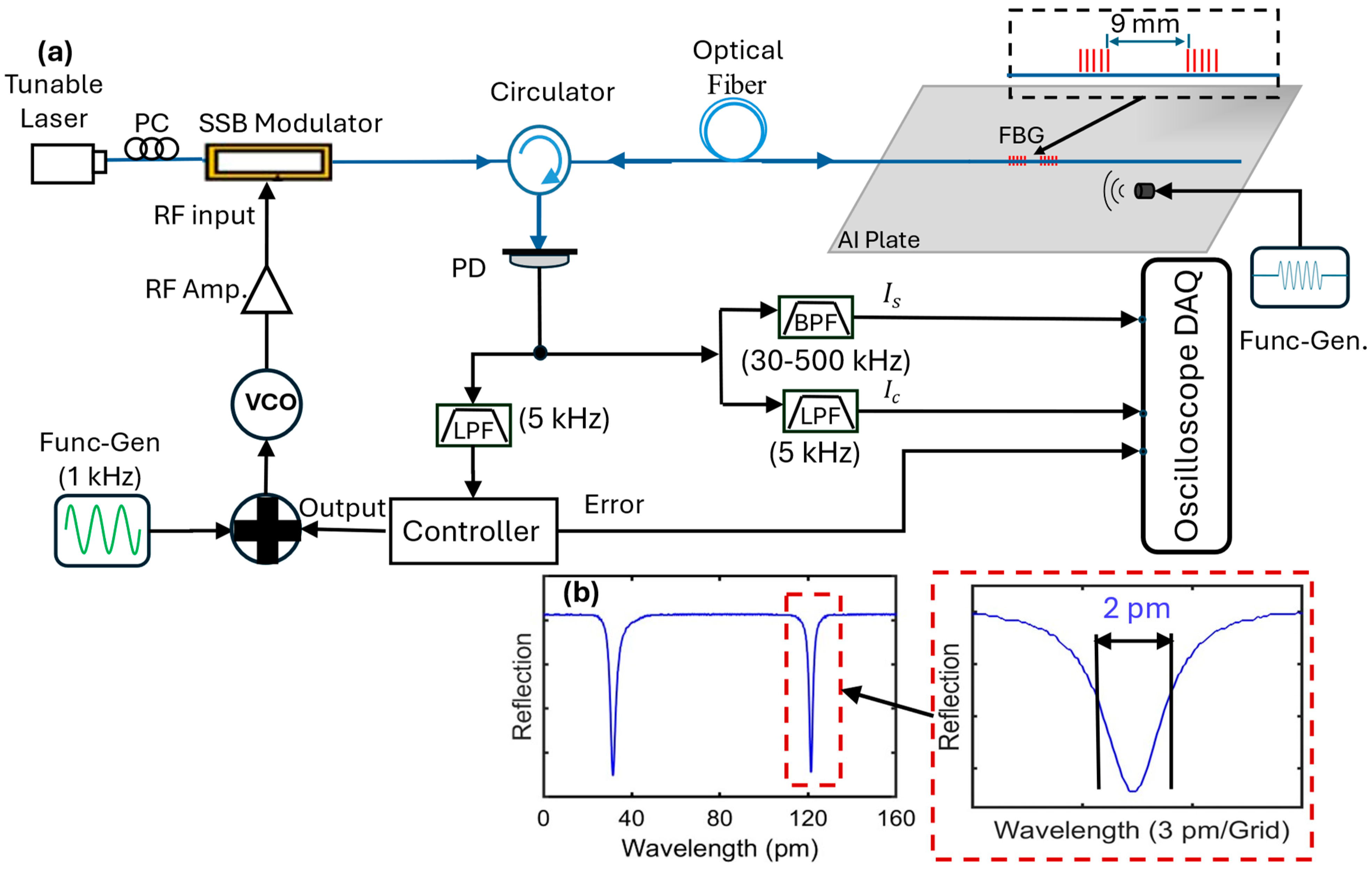
To demonstrate the locking and calibration of fiber-optic ultrasonic sensors using single-sideband-modulated laser schemes, the experimental setup was constructed as illustrated in Figure 2. The sensor employed in this experiment was a high-finesse inline FP interferometer formed by two FBGs separated by a span of 8 mm long fiber. The two FBGs were identical, each having a length of 4 mm and a reflectivity of ~95%. The reflection spectrum of the sensor features a few notches within the reflection bandwidth of the FBG with a spectral separation of ~80 pm between neighboring notches. The one closest to the FBG peaks shows the narrowest spectrum and was selected for locking the laser for ultrasound detection. Figure 2b shows the spectrum of the notch measured using a wavelength-scanning laser and a photodetector, exhibiting a 3 dB spectral width of approximately 2 pm. The sensor was positioned on the surface of an aluminum plate, and an ultrasonic couplant gel was applied to ensure efficient coupling of ultrasonic waves between the plate and the sensor. A piezoelectric transducer was used to generate the ultrasonic signal, which was driven by a function generator set to produce a 120 kHz, 15 V peak-to-peak sinusoidal waveform with 5-cycle bursts. The signal had a repetition rate of 0.025 ms (equivalent to 40 Hz), ensuring consistent and repeatable ultrasonic pulses for testing the performance of the sensor system.
We employed a wavelength-tunable external-cavity laser (New Focus 6700) as the primary light source combined with a variable optical attenuator (VOA). This setup allows precise adjustments of the operating points and control over the optical power, which are critical for evaluating our demodulation and calibration schemes. To ensure optimal modulation efficiency of the phase modulator, we controlled the light polarization using a polarization controller (PC). A commercial single-sideband generation module with an integrated DP-MZI, 90° hybrid coupler, and DC bias was used. The module has a bandwidth of 18 GHz and was driven by a composite signal comprising two components: a high-frequency signal generated by a voltage-controlled oscillator (VCO) with a tunable range of 5–10 GHz, adjusted via a 0–20 V DC input voltage, and a low-frequency signal of 1 kHz, generated by a separate function generator. The 1 kHz signal, with a peak-to-peak voltage of 50 mV, was used for calibration, while the VCO signal served as the carrier for edge-filter demodulation. The VCO output frequency was amplified by 20 dB to achieve the desirable modulation depth necessary for effective carrier generation in quadrature demodulation. After the module, the light passes through a circulator and reaches the sensor. The light reflected from the sensor is then directed to an amplified photodetector. We directly filtered the ultrasound-induced signal ( i s ) from the photodetector output using bandpass filters (30–500 kHz) and the calibration signal ( i c ) using lowpass filters (5 kHz). The DC component of the photodetector output, which captures the light reflected from the sensor, carries the information about the operating point. This component is filtered and utilized to lock the sideband onto the slope of the sensor’s reflection spectrum, ensuring precise alignment. The locking was achieved using a commercial PID controller. The bandwidth of the controller was set to be ~100 Hz. This frequency was sufficient for ensuring that the laser wavelength locking resisted low-frequency spectral shift of the sensor caused by environmental perturbations; in the meantime, it allowed the calibration signal, which was much higher than the controller bandwidth, to be detected.

4. Results

4.1. Sideband Locking for Edge-Filter Detection

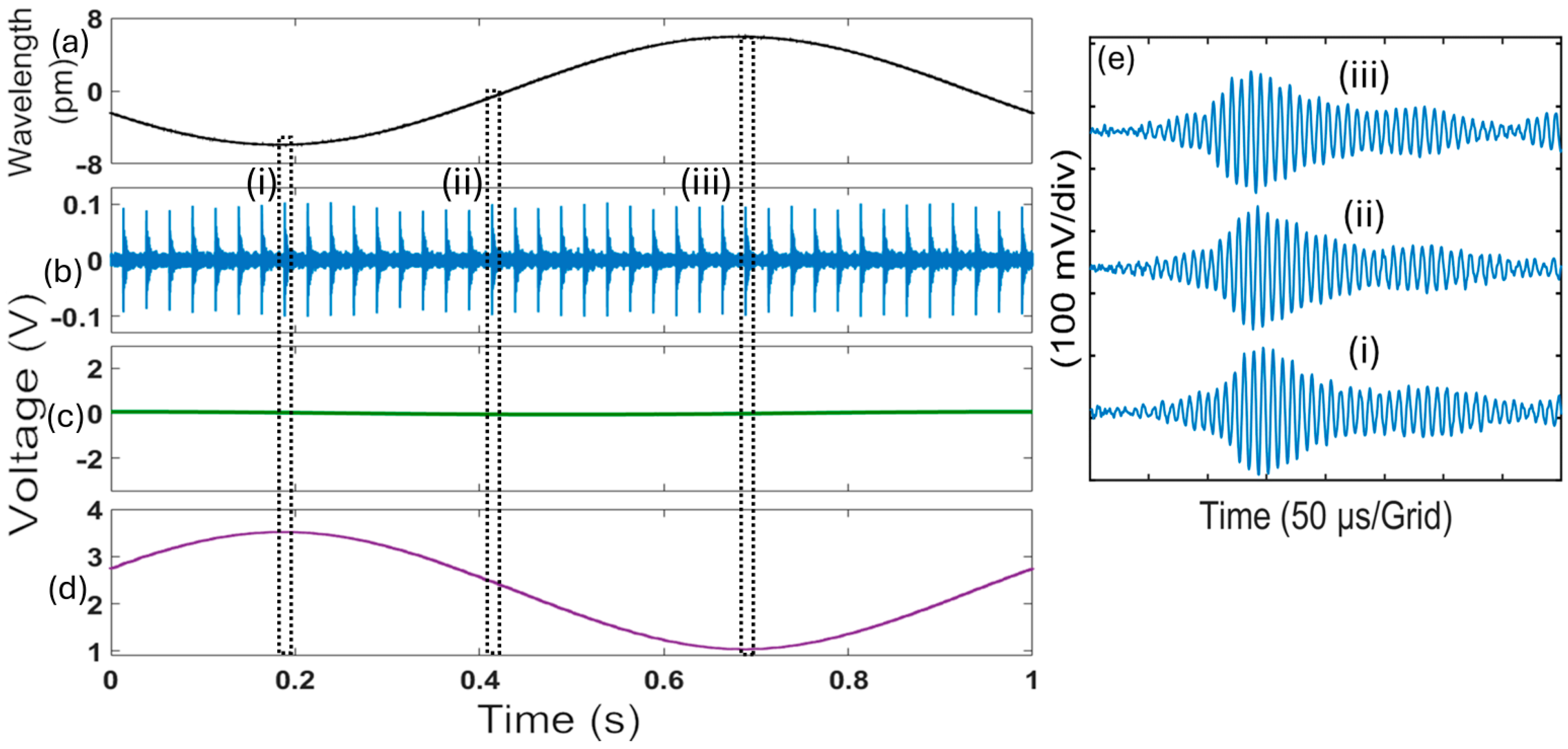
We evaluated the robustness of the real-time wavelength tuning and the locking method against signal variations caused by operating-point changes. The operating point was changed by scanning the laser wavelengths using a 1 Hz sinusoidal wave, which resulted in a sinusoidal modulation of the laser wavelength with peak-to-peak wavelength shift of 12 pm, as shown in Figure 3a. This wavelength shift range is six times the spectral width (2 pm) of the spectral notch. Figure 3d shows the output from the PID controller under the locked condition when the feedback control loop was closed. This signal was amplified and injected into the single-sideband generation module to tune the laser sideband for locking. The controller output signal was opposite to the modulation signal for the laser wavelength, which is expected as the controller output tuned the laser sideband to maintain it at the same location on the spectral slope of the sensor. The error signal, shown in Figure 3c, is close to 0, which verifies that the system was in locked condition. Figure 3b shows the ultrasonic pulses that were measured by the sensor system as the wavelength was scanned. The recorded pulses exhibited consistent amplitudes during the whole range of the laser wavelength scanning. The measured pulses when the laser wavelength was at three different locations are shown in more detail in Figure 3e, demonstrating the robustness of the real-time wavelength tuning and locking method in compensating for signal variations caused by operating-point changes.
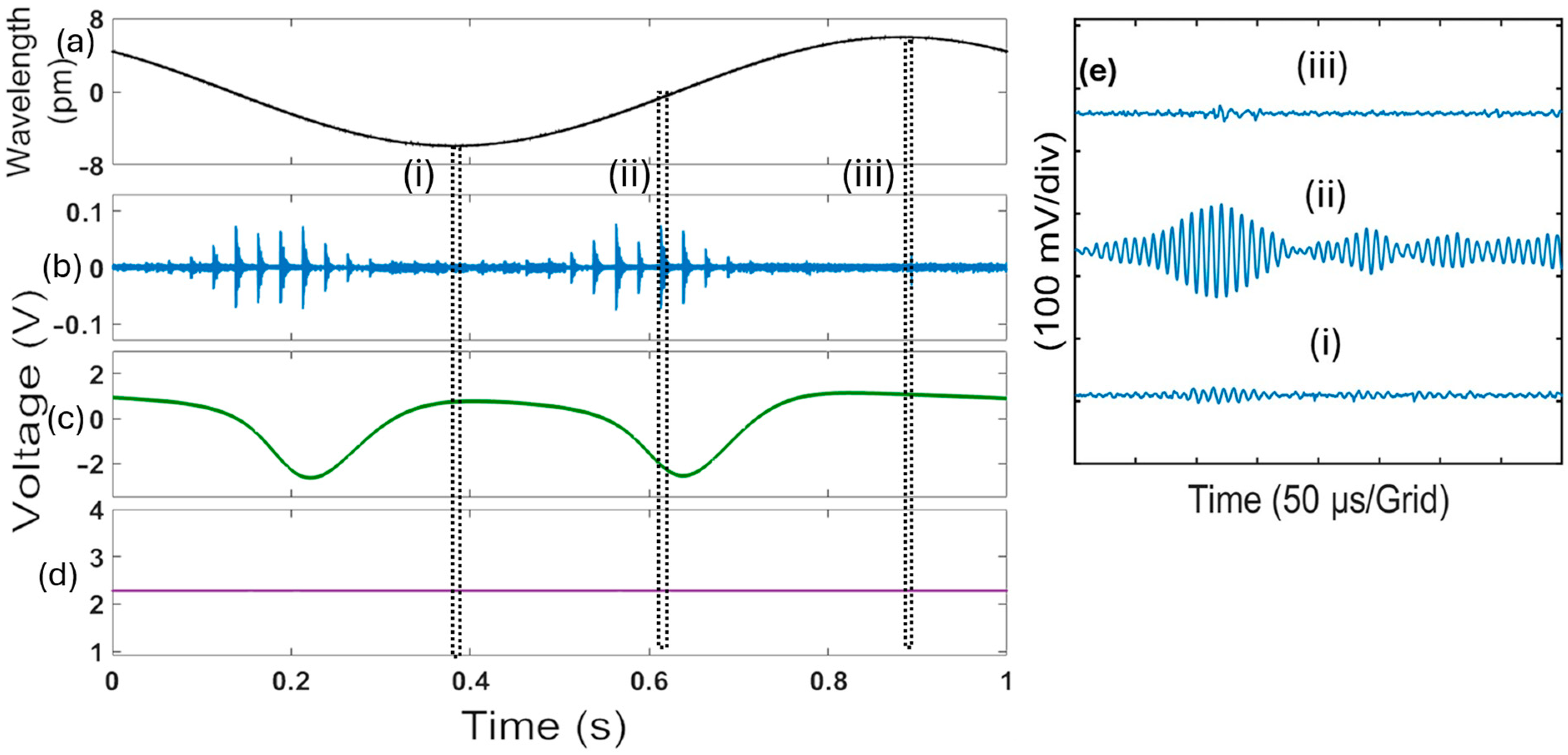
For comparison, we conducted an experiment in which the feedback control loop was open and the system was in an unlocked condition. The other conditions in this experiment were identical to those in the above experiment. The results are presented in Figure 4. In this unlocked state, the controller output, shown in Figure 4d, was constant and unresponsive to the operating-point changes from the laser wavelength changes shown in Figure 4a. The error signal in Figure 4c shows a form resembling the spectral notch of the sensor, consistent with the unlocked state when the laser wavelength scanned over the spectral notch. The output of the sensor system in response to the ultrasonic signals generated from the piezoelectric transducer is shown in Figure 4b, indicating that that the laser wavelength scanning caused significant fluctuations in the ultrasound signals due to operating-point variations. Figure 4e shows the response of the sensor system at three different laser wavelengths. The amplitudes of the ultrasound signals fluctuated significantly and disappeared at certain points, demonstrating instability in the sensor’s performance.
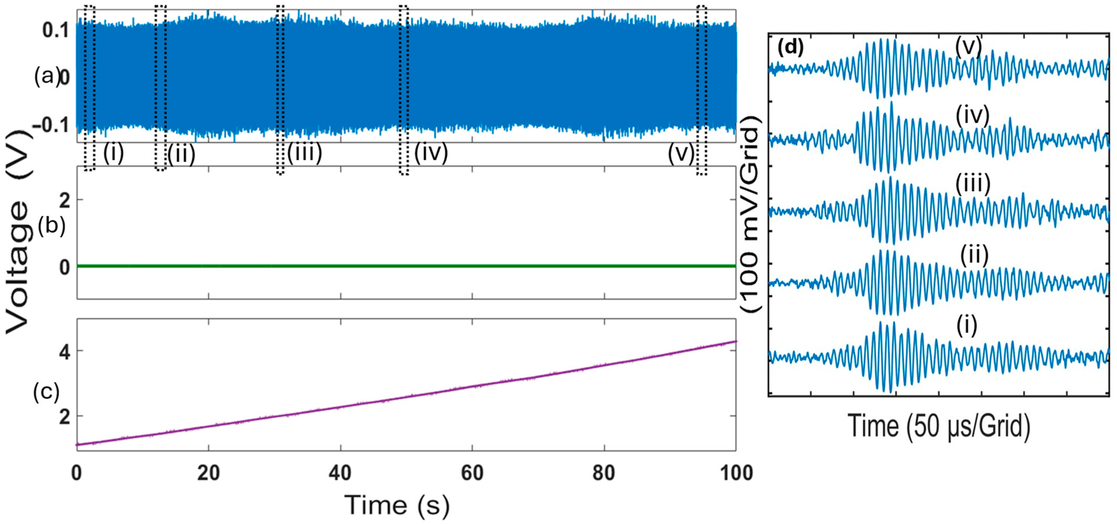
To further validate the effectiveness of our real-time wavelength tuning and locking method in practical applications, we conducted an experiment where the sensor was subjected to controlled thermal variations. Over a period of 100 s, we gradually increased the temperature from 25.0 °C to 26.4 °C. Given that the FBG sensor exhibits a wavelength shift of approximately 10 pm/°C, this temperature increase corresponds to a total wavelength shift of about 14 pm, or seven times the spectral width of the spectral notch.
The results are presented in Figure 5a–d, which shows the various signals under the applied thermal variation. As shown in Figure 5a, the ultrasound signal remained stable with constant amplitudes throughout the temperature change, demonstrating that our system effectively maintained performance despite the induced wavelength shifts. Figure 5d provides a detailed view of the stabilized ultrasound signals at five different temperature points, highlighted in Figure 5a. The minimal variation in signal amplitude across these points underscores the efficacy of our method in maintaining signal integrity under thermal stress. This stability confirms the method’s ability to compensate for temperature-induced variations, ensuring consistent sensor operation without significant fluctuations in the amplitude of the ultrasound signals.
For comparison, the experiment was repeated when the sensor system was in the unlocked state. The sensor was subjected to the same controlled thermal variations as before, with the temperature gradually increased from 25.00 °C to 26.35 °C over 100 s.
The results presented in Figure 6a–d show that without locking, the sensor output exhibited significant instability due to the temperature-induced wavelength shifts. As presented in Figure 6a, the ultrasound signal rapidly decreased in amplitude immediately after the heat was applied and disappeared entirely after approximately 30 s, corresponding to a temperature increase of less than 0.35 °C. Figure 6d provides a detailed view of the stabilized ultrasound signals at five different temperature points highlighted in Figure 6a. This rapid loss of signal indicates that even minimal temperature changes can severely impact the sensor’s performance in the unlocked state, in which case the sensor system cannot function reliably under thermal stress.

4.2. Real-Time In Situ Sensor Calibration

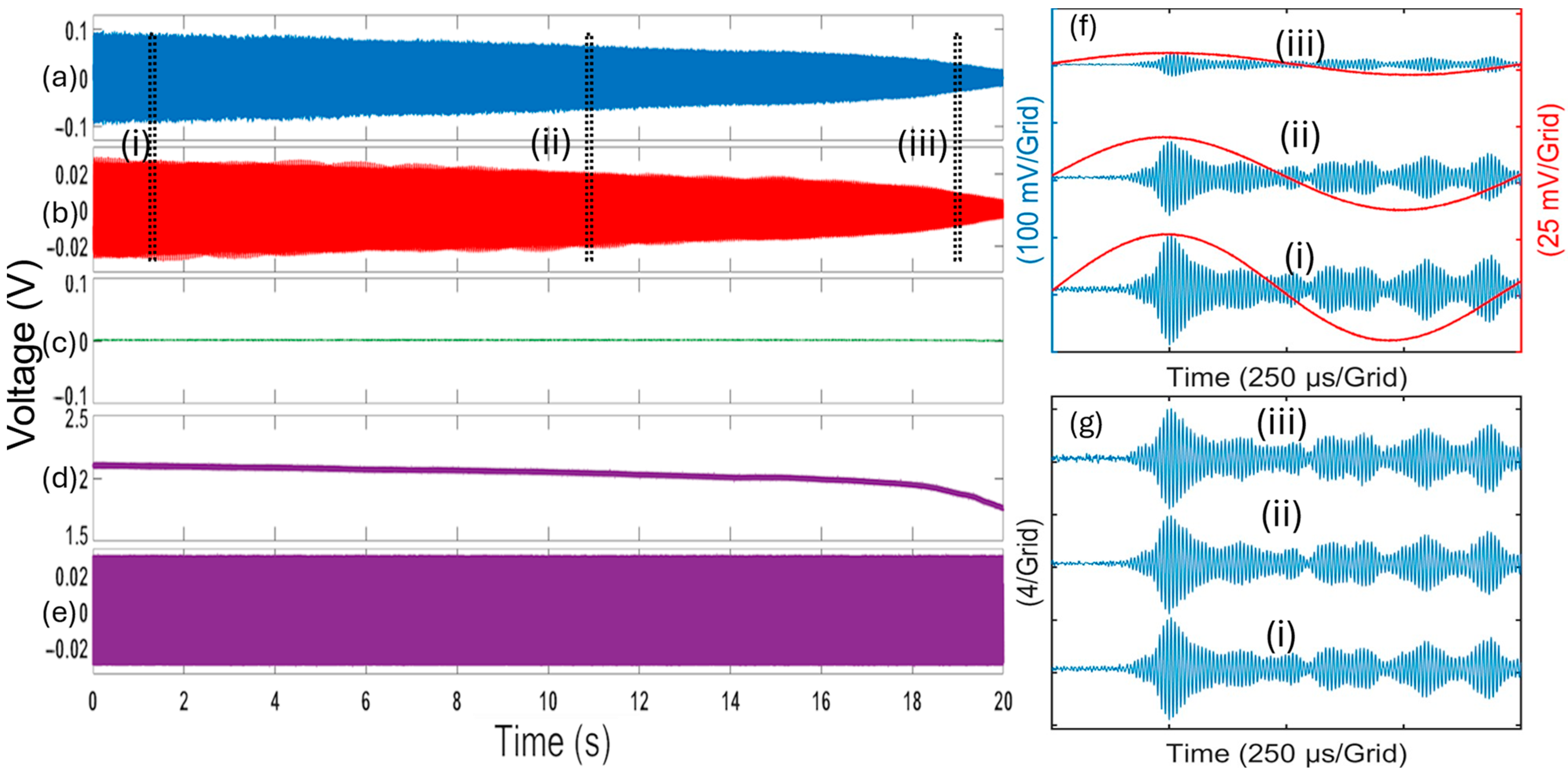
We evaluated the effectiveness of the proposed real-time in situ calibration method against optical power fluctuations. The optical power changes were introduced by manually adjusting the variable optical attenuator (VOA) that reduced the optical power transmitted into the sensor. A data acquisition (DAQ) system with a sampling rate of 2 MS/s was utilized to continuously record both the ultrasound-induced signals ( i s ) and the calibration signals ( i c ). The resulting data are illustrated in Figure 7. The ultrasound-induced signals ( i s ) and the calibration signals ( i c ) are directly proportional to the optical power. Figure 7a,b demonstrate that the variations in optical power, as indicated by the envelopes of the ultrasound signal ( i s ), are consistent with those of the calibration signal ( i c ). As part of our results, Figure 7c–e illustrate key signals within the system. Figure 7c shows the error signal. It remained at zero throughout the experiment, indicating that the sensor system was in the locked state during the process. Figure 7f provides a detailed view of the ultrasound signals ( i s ) and calibration signal ( i c ) obtained at the three operating points highlighted in Figure 7a,b, which shows large variations in their amplitudes. The amplitude of the calibration signal, which is the system’s response to a known laser wavelength variation, contains information on the system’s sensitivity. The calibration is carried out by simply dividing the detected ultrasonic signal by the amplitude of the calibration signal. Figure 7g shows the recorded ultrasonic signals after calibration, which exhibit approximately equal amplitude, indicating the effectiveness of the real-time in situ calibration method against optical power variations.

5. Discussion

In this work, a wavelength-tunable external-cavity diode laser with a modified Littman–Metcalf configuration was used as the light source. Such lasers typically are bulky and have relatively high cost, which limits their practical applications. However, the laser was chosen because its continuous wavelength-tuning capability allows us to conveniently study the proposed wavelength-locking approach to resist laser wavelength drift and operating-point changes. For practical applications, low-cost, low-noise, widely tunable diode lasers based on the Vernier effect would be more attractive. Furthermore, the wavelength tuning range using the single-sideband generation with a DP-MZI is small, limited by the frequency range of the VCO and the bandwidth of the DP-MZI. Therefore, it can only work for relatively small environmental perturbations. Future work will include combining the agile wavelength tuning capability demonstrated in this work and the relatively slow but wide-range wavelength tuning of the lasers for locking the laser wavelength to the sensor spectrum, which will greatly increase the stability and reliability of edge-filter detection against larger and more rapid environmental perturbations than demonstrated in this work. The wide tuning range (often covering the whole C-band) of these lasers allows one laser to demodulate multiple FBG-FPI ultrasonic sensors multiplexed in the wavelength domain.
With the capability for high speed and high precision wavelength tuning over a range up to 10 GHz, single-sideband generation and modulation for laser wavelength locking may be useful for many other applications. For example, a key component in a high-performance optical frequency-domain reflectometry (OFDR) system is a tunable laser source whose frequency can change linearly with time [24]. The method in this work may be used to compensate for the nonlinearity of lasers. Another potential application is for frequency stabilization of lasers by locking the laser wavelength to a stabilized optical resonator [25,26]. In addition to high-sensitivity interferometer sensors, such lasers are needed in many other applications such as high-resolution spectroscopy and optical atomic clocks.

6. Conclusions

In this work, we have demonstrated a robust and effective method for real-time wavelength tuning and locking in edge-filter detection of fiber-optic ultrasonic sensors. By employing laser single-sideband generation with a DP-MZI, we achieved agile wavelength tunability and stable laser operation, addressing the challenges posed by the lack of cost-effective laser sources with good noise performance.
Our method also incorporates real-time in situ calibration of the sensor response to ultrasound-induced wavelength shifts, enhancing measurement accuracy. The calibration was achieved by producing sinusoidal calibration laser wavelength modulation with a constant amplitude at a frequency much lower than the ultrasound frequency. The responses to the calibration laser wavelength modulation were extracted from the overall system output. The amplitude of the calibration signal contains information on the system sensitivity, which was used to gauge the response to ultrasound in real time and in situ.
Experimental results obtained from a fiber-optic ultrasonic sensor based on a high-finesse FP interferometer formed by two FBGs confirmed the effectiveness of our approach. The system maintained stable sensor performance under varying operating conditions, including laser wavelength drifts and temperature variations. The ultrasound signal remained stable and detectable even when the sensor was subjected to controlled thermal variations. The proposed real-time in situ calibration method was also validated experimentally by manually attenuating the optical power of the light source. Before the calibration scheme was applied, the amplitudes of the detected signal in response to ultrasonic pulses with constant amplitudes changed linearly with the optical power. The calibration yielded signals with consistent amplitudes, demonstrating the capability and the effectiveness of the proposed real-time in situ calibration method.

Author Contributions

Conceptualization: M.H.; methodology: M.A. and M.H.; validation: M.A.; writing: M.A. and M.H.; funding acquisition: M.H. All authors have read and agreed to the published version of the manuscript.

Funding

This research was funded by the Office of Naval Research, grant numbers N000142212321 and N000142112273.

Institutional Review Board Statement

Not applicable.

Informed Consent Statement

Not applicable.

Data Availability Statement

The data underlying the results presented in this paper are not publicly available at this time but may be obtained from the authors upon reasonable request.

Acknowledgments

M. Alshammari is supported by a scholarship from University of Hafar Albatin in Saudi Arabia.

Conflicts of Interest

The authors declare no conflicts of interest. The funders had no role in the design of the study; in the collection, analyses, or interpretation of data; in the writing of the manuscript; or in the decision to publish the results.

References

  1. Soman, R.; Wee, J.; Peters, K. Optical fiber sensors for ultrasonic structural health monitoring: A review. Sensors 2021, 21, 7345. [Google Scholar] [CrossRef] [PubMed]
  2. Zhou, J.; Jokerst, J.V. Photoacoustic imaging with fiber optic technology: A review. Photoacoustics 2020, 20, 100211. [Google Scholar] [CrossRef]
  3. Rosenthal, A.; Razansky, D.; Ntziachristos, V. High-sensitivity compact ultrasonic detector based on a pi-phase-shifted fiber Bragg grating. Opt. Lett. 2011, 36, 1833–1835. [Google Scholar] [CrossRef]
  4. Wu, Q.; Okabe, Y. High-sensitivity ultrasonic phase-shifted fiber Bragg grating balanced sensing system. Opt. Express 2012, 20, 28353–28362. [Google Scholar] [CrossRef]
  5. Zhang, Q.; Zhu, Y.; Luo, X.; Liu, G.; Han, M. Acoustic emission sensor system using a chirped fiber-Bragg-grating Fabry–Perot interferometer and smart feedback control. Opt. Lett. 2017, 42, 631–634. [Google Scholar] [CrossRef] [PubMed]
  6. Wei, H.; Krishnaswamy, S. Polymer micro-ring resonator integrated with a fiber ring laser for ultrasound detection. Opt. Lett. 2017, 42, 2655–2658. [Google Scholar] [CrossRef]
  7. Li, A.; Jing, Z.; Liu, Y.; Liu, Q.; Huang, Z.; Cheung, Y.; Zhang, Y.; Han, M.; Peng, W. Quadrature operating point stabilizing technique for fiber-optic Fabry–Perot sensors using Vernier-tuned distributed Bragg reflectors laser. IEEE Sens. J. 2020, 21, 2084–2091. [Google Scholar] [CrossRef]
  8. Mao, X.; Yuan, S.; Zheng, P.; Wang, X. Stabilized fiber-optic Fabry–Perot acoustic sensor based on improved wavelength tuning technique. J. Light. Technol. 2017, 35, 2311–2314. [Google Scholar] [CrossRef]
  9. Tsuda, H.; Kumakura, K.; Ogihara, S. Ultrasonic sensitivity of strain-insensitive fiber Bragg grating sensors and evaluation of ultrasound-induced strain. Sensors 2010, 10, 11248–11258. [Google Scholar] [CrossRef]
  10. Yu, F.; Okabe, Y. Fiber-Optic Sensor-Based Remote Acoustic Emission Measurement in a 1000° C Environment. Sensors 2017, 17, 2908. [Google Scholar] [CrossRef]
  11. Yu, F.; Okabe, Y.; Wu, Q.; Shigeta, N. Fiber-optic sensor-based remote acoustic emission measurement of composites. Smart Mater. Struct. 2016, 25, 105033. [Google Scholar] [CrossRef]
  12. Qiao, Y.; Zhou, Y.; Krishnaswamy, S. Adaptive demodulation of dynamic signals from fiber Bragg gratings using two-wave mixing technology. Appl. Opt. 2006, 45, 5132–5142. [Google Scholar] [CrossRef] [PubMed]
  13. Kirikera, G.R.; Balogun, O.; Krishnaswamy, S. Adaptive fiber Bragg grating sensor network for structural health monitoring: Applications to impact monitoring. Struct. Health Monit. 2011, 10, 5–16. [Google Scholar] [CrossRef]
  14. Hulme, J.; Doylend, J.; Bowers, J. Widely tunable Vernier ring laser on hybrid silicon. Opt. Express 2013, 21, 19718–19722. [Google Scholar] [CrossRef] [PubMed]
  15. Barton, J.S.; Skogen, E.J.; Masanovic, M.L.; DenBaars, S.P.; Coldren, L.A. A widely tunable high-speed transmitter using an integrated SGDBR laser-semiconductor optical amplifier and Mach-Zehnder modulator. IEEE J. Sel. Top. Quantum Electron. 2003, 9, 1113–1117. [Google Scholar] [CrossRef]
  16. Bustillos-Barcaya, M.C.; Rinalde, G.F.; Bulus-Rossini, L.A.; Costanzo-Caso, P.A. Y-branch tunable laser design: Modeling, control and experimental validation. Opt. Laser Technol. 2021, 140, 107040. [Google Scholar] [CrossRef]
  17. Alshammari, M.; Chu, Y.; Han, M. Real-time in situ phase sensitivity calibration of interferometric fiber-optic ultrasonic sensors. Opt. Lett. 2024, 49, 5336–5339. [Google Scholar] [CrossRef] [PubMed]
  18. Higuma, K.; Oikawa, S.; Hashimoto, Y.; Nagata, H.; Izutsu, M. X-cut lithium niobate optical single-sideband modulator. Electron. Lett. 2001, 37, 515–516. [Google Scholar] [CrossRef]
  19. Janner, D.; Tulli, D.; Belmonte, M.; Pruneri, V. Waveguide electro-optic modulation in micro-engineered LiNbO3. J. Opt. A Pure Appl. Opt. 2008, 10, 104003. [Google Scholar] [CrossRef]
  20. Izutsu, M.; Shikama, S.; Sueta, T. Integrated optical SSB modulator/frequency shifter. IEEE J. Quantum Electron. 1981, 17, 2225–2227. [Google Scholar] [CrossRef]
  21. Erkılınç, M.S.; Li, Z.; Pachnicke, S.; Griesser, H.; Thomsen, B.C.; Bayvel, P.; Killey, R.I. Spectrally efficient WDM Nyquist pulse-shaped 16-QAM subcarrier modulation transmission with direct detection. J. Light. Technol. 2015, 33, 3147–3155. [Google Scholar] [CrossRef]
  22. Zhang, L.; Zuo, T.; Mao, Y.; Zhang, Q.; Zhou, E.; Liu, G.N.; Xu, X. Beyond 100-Gb/s transmission over 80-km SMF using direct-detection SSB-DMT at C-band. J. Light. Technol. 2015, 34, 723–729. [Google Scholar] [CrossRef]
  23. Li, Z.; Erkılınç, M.S.; Shi, K.; Sillekens, E.; Galdino, L.; Thomsen, B.C.; Bayvel, P.; Killey, R.I. SSBI mitigation and the Kramers–Kronig scheme in single-sideband direct-detection transmission with receiver-based electronic dispersion compensation. J. Light. Technol. 2017, 35, 1887–1893. [Google Scholar] [CrossRef]
  24. Qu, S.; Xu, Y.; Huang, S.; Sun, M.; Wang, C.; Shang, Y. Recent advancements in optical frequency-domain reflectometry: A review. IEEE Sens. J. 2022, 23, 1707–1723. [Google Scholar] [CrossRef]
  25. Drever, R.W.; Hall, J.L.; Kowalski, F.V.; Hough, J.; Ford, G.; Munley, A.; Ward, H. Laser phase and frequency stabilization using an optical resonator. Appl. Phys. B 1983, 31, 97–105. [Google Scholar] [CrossRef]
  26. Ludlow, A.D.; Huang, X.; Notcutt, M.; Zanon-Willette, T.; Foreman, S.; Boyd, M.; Blatt, S.; Ye, J. Compact, thermal-noise-limited optical cavity for diode laser stabilization at 1 × 10⁻¹⁵. Opt. Lett. 2007, 32, 641–643. [Google Scholar] [CrossRef]
Figure 1. Schematics of (a) the proposed fiber-optic ultrasonic sensor system with edge-filter detection and real-time in situ calibration and (b) the single-sideband generation module. (c) Illustration of laser wavelength locking for ultrasound detection and laser wavelength modulation for calibration.
Photonics 11 01063 g001
Figure 2. (a) Schematic of the experimental setup. (b) Measured reflection spectrum of the sensor.
Photonics 11 01063 g002
Figure 3. Locking the single sideband to the spectral slope of the sensor against laser wavelength variation. (a) Sinusoidal laser wavelength modulation with a peak-to-peak wavelength shift of 12 pm, (b) recorded sensor system output in response to the ultrasound (is), (c) error signal of the feedback control loop, (d) the output from the controller that feeds the VCO, and (e) a detailed view of the ultrasound signals (is) obtained at the three operating points indicated in with (i), (ii), and (iii) (b).
Photonics 11 01063 g003
Figure 4. Results when the feedback control loop was open. (a) Sinusoidal laser wavelength modulation with a peak-to-peak wavelength shift of 12 pm. (b) Recorded sensor system output in response to the ultrasound (is), (c) error signal of the feedback control loop, (d) the output from the controller that feeds the VCO, and (e) a detailed view of the ultrasound signals (is) obtained at the three operating points indicated with (i), (ii), and (iii) in (b).
Photonics 11 01063 g004
Figure 5. Locking the single sideband to the spectral slope of the sensor against thermal-induced wavelength shift of the sensor. (a) Recorded sensor system output in response to the ultrasound (is), (b) error signal of the feedback control loop, (c) the output from the controller that feeds the VCO, and (d) a detailed view of the ultrasound signals (is) obtained at the five operating points indicated with (i), (ii), (iii), (iv) and (v) in (a).
Photonics 11 01063 g005
Figure 6. Results when the feedback control loop was open. (a) Recorded sensor system output in response to the ultrasound (is); (b) error signal of the feedback control loop; (c) the output from the controller that feeds the VCO; and (d) a detailed view of the ultrasound signals (is) obtained at the five operating points indicated with (i), (ii),(iii), (iv) and (v) in (a), showing large variations in amplitude.
Photonics 11 01063 g006
Figure 7. Results for demonstration of sensor calibration. (a) Recorded sensor system output in response to the ultrasound (is); (b) calibration signal (ic); (c) error signal of the feedback control; (d) controller output that feeds the VCO; (e) 50 mVpp 1 kHz modulation signal for generating the calibration; (f) detailed view of the ultrasound signals, is (blue), and calibration signal, ic (red), obtained at the three operating points indicated in (a); and (g) the corresponding signals after calibration.
Photonics 11 01063 g007
Disclaimer/Publisher’s Note: The statements, opinions and data contained in all publications are solely those of the individual author(s) and contributor(s) and not of MDPI and/or the editor(s). MDPI and/or the editor(s) disclaim responsibility for any injury to people or property resulting from any ideas, methods, instructions or products referred to in the content.