Article

Bidirectional Propagation Properties of Partially Coherent Laguerre–Gaussian Beams in Atmospheric Turbulence and Plasma

1
Shandong Provincial Engineering and Technical Center of Light Manipulations & Shandong Provincial Key Laboratory of Optics and Photonic Device, School of Physics and Electronics, Shandong Normal University, Jinan 250014, China
2
Collaborative Innovation Center of Light Manipulation and Applications, Shandong Normal University, Jinan 250358, China
3
Joint Research Center of Light Manipulation Science and Photonic Integrated Chip of East China Normal University and Shandong Normal University, East China Normal University, Shanghai 200241, China
*
Authors to whom correspondence should be addressed.
Photonics 2024, 11(12), 1111; https://doi.org/10.3390/photonics11121111
Submission received: 29 October 2024 / Revised: 15 November 2024 / Accepted: 22 November 2024 / Published: 24 November 2024
(This article belongs to the Section Optical Communication and Network)

Abstract

:
The bidirectional propagation properties of partially coherent Laguerre–Gaussian (PCLG) beams under atmospheric turbulence and plasma were numerically investigated. The corresponding analytical formulas for the intensity distribution, effective beam width, and M2 factor of PCLG beams were derived by utilizing the generalized Collins integral formula, atmospheric turbulence theory, and second-order moments theory of the Wigner distribution function. The intensity distribution of the PCLG beams ultimately evolved into a Gaussian-like intensity distribution. Additionally, the effective beam width and M2 factor could be less affected by selecting appropriate parameter values for the beam order, transverse coherence width, and wavelength of the PCLG beam. The impact of parameters such as the beam order, transverse coherence width, and wavelength for reverse transmission on the PCLG beam propagation properties was greater than that for forward transmission. These results are beneficial for applications in free-space optical communications.

1. Introduction

Partially coherent beams have been extensively studied, both theoretically and experimentally, because of their potential in free-space optical communication [1], atom cooling [2], nonlinear optics [3,4,5], inertial confinement fusion [6], ghost imaging [7,8], and quantum optics applications [9]. Partially coherent beams reportedly have stronger turbulence resistance than fully coherent beams [10,11,12,13,14]. Scholars have investigated the propagation properties of various partially coherent beams in atmospheric turbulence, such as Hermite–Gaussian correlated Schell model beams, partially coherent flat-topped beams, twisted Gaussian Schell model beams, and partially coherent Laguerre–Gaussian (PCLG) beams [15,16,17,18,19,20,21,22].
The generation, propagation, and application of Laguerre–Gaussian (LG) beams are primary areas of concern. LG modes are a class of eigenmodes that can propagate in free space and carry photon orbital angular momentum, with LG beams being widely used in laser optics, material processing, and atomic optics applications, including atom interferometers [23], nanoparticle trapping [24], atom guiding [25,26], atom trapping [27], and electron acceleration [28] applications. The propagation properties of an LG beam through paraxial optical systems with or without holes for micro differential alignment has been investigated [29]; variations in the intensity and polarization properties of the PCLG vector beams under atmospheric turbulence have also been studied [30]; and the evolution properties of the angular width and propagation factor of partially coherent standard LG beams propagating in an anisotropic turbulent plasma have been numerically examined [31]. However, the bidirectional propagation properties of PCLG beams in atmospheric turbulence and plasma require further investigation.
When an aircraft enters or returns to the atmosphere at high speed, a plasma sheath is formed on its surface owing to the compression and friction of air. This plasma sheath can affect the quality of communication between land- and aircraft-based radar systems and can even lead to communication interruptions [32]. In the past decade, the propagation properties of fully coherent beams and partially coherent beams propagating in turbulent plasma have attracted widespread attention [33,34,35,36,37]; the propagation properties of two types of partially coherent vortex beams in anisotropic turbulent plasma were studied and compared [38]; the effect of anisotropic plasma turbulence on the transmission characteristics of LG beams in a spiral spectrum has been studied [39]; and the intensity of refractive index fluctuations in plasma sheath turbulence, wavelength, and propagation distance are important factors affecting the quality of Gaussian beams [40].
The purpose of this study is to investigate the evolution of the intensity, effective beam width, and M2 factor of PCLG beams propagating bidirectionally in atmospheric turbulence and plasma based on the generalized Collins integral formula, atmospheric turbulence theory, and second-order moment theory of the Wigner distribution function (WDF). Corresponding analytical expressions are derived, and numerical simulations are conducted. The simulation results indicate that the parameters of atmospheric turbulence and source beam can affect the bidirectional propagation properties of PCLG beams in atmospheric turbulence and plasma. These findings could be useful for free-space optical communication applications.

2. Intensity Distribution

The electric field distribution of the LG beams at the source plane (z = 0) can be expressed as follows [41]:
E p l ( r , φ ; 0 ) = ( 2 r w 0 2 ) l L p l ( 2 r 2 w 0 2 ) exp ( r 2 w 0 2 ) exp ( i l φ ) ,
where (r, φ; 0) denotes an arbitrary position vector at z = 0 in the cylindrical coordinate system and r = (x, y), L p l ( · ) denote the Laguerre polynomial with mode orders l and p, and w0 denotes the beam waist. The LG beams become Gaussian beams when l = 0 and p = 0.
Applying the following relationship between the LG and Gaussian modes [42],
e i l φ ρ l L p l ( ρ 2 ) = ( 1 ) p 2 2 p + l p ! m = 0 p s = 0 l i n ( p m ) ( l s ) H 2 m + l s ( x ) H 2 p 2 m + s ( y ) ,
where Hm(x) denotes the Hermite polynomial of order m, and ( p m ) and ( l s ) denote binomial coefficients. Submitting Equation (2) to Equation (1), Equation (1) can be expressed in the following alternative form in Cartesian coordinates:
E p l ( x , y ; 0 ) = ( 1 ) p 2 2 p + l p ! m = 0 p s = 0 l i s ( p m ) ( l s ) H 2 m + l s ( 2 x w 0 ) H 2 p 2 m + s ( 2 y w 0 ) exp ( x 2 + y 2 w 0 2 ) .
The PCLG beam can be represented by the cross-spectral density (CSD) [43]:
W ( x 1 , y 1 , x 2 , y 2 ; z ) = [ E p l ( x 1 , y 1 ; z ) ] * [ E p l ( x 2 , y 2 ; z ) ] ,
where <·> and * denote the ensemble average and complex conjugate, respectively.
The CSD of a PCLG beam at the source plane (z = 0) can be expressed as follows:
W ( x 1 , y 1 , x 2 , y 2 ; 0 ) = I ( x 1 , y 1 ; 0 ) I ( x 2 , y 2 ; 0 ) g ( x 1 x 2 , y 1 y 2 ; 0 ) ,
where I(x, y; z) denotes the intensity distribution and can be determined as follows:
I ( x , y ; z ) = | E p l ( x , y ; 0 ) | 2 ,
here g(x1x2, y1y2; 0) denotes the spectral degree of coherence and can be assumed to be a Gaussian form as follows:
g ( x 1 x 2 , y 1 y 2 ; 0 ) = exp [ ( x 1 x 2 ) 2 + ( y 1 y 2 ) 2 2 σ g 2 ] ,
where σg denotes the transverse coherence width.
Substituting Equations (3), (6), and (7) into Equation (5), the CSD of the PCLG beam at the source plane can be expressed as follows [44]:
W ( x 1 , y 1 , x 2 , y 2 ; 0 ) = 1 2 4 p + 2 l ( p ! ) 2 m = 0 p n = 0 l h = 0 p s = 0 l ( i n ) * i s ( p m ) ( l n ) ( p h ) ( l s )          × H 2 m + l n ( 2 x 1 w 0 ) H 2 h + l s ( 2 x 2 w 0 ) exp ( x 1 2 + x 2 2 w 0 2 ) exp ( ( x 1 x 2 ) 2 2 σ g 2 )          × H 2 p 2 m + n ( 2 y 1 w 0 ) H 2 p 2 h + s ( 2 y 2 w 0 ) exp ( y 1 2 + y 2 2 w 0 2 ) exp ( ( y 1 y 2 ) 2 2 σ g 2 ) .
The CSD of a partially coherent beam through random media can be obtained using the generalized Collins integral [35], as follows:
W ( u 1 , v 1 , u 2 , v 2 ; z ) = ( 1 λ | B | ) 2 W ( x 1 , y 1 , x 2 , y 2 ; 0 ) exp [ H ( r 1 , r 2 , ρ 1 , ρ 2 ; z ) ]          × exp [ i k 2 B [ A ( x 1 2 x 2 2 ) 2 ( x 1 u 1 x 2 u 2 ) + D ( u 1 2 u 2 2 ) ] ]          × exp [ i k 2 B [ A ( y 1 2 y 2 2 ) 2 ( y 1 v 1 y 2 v 2 ) + D ( v 1 2 v 2 2 ) ] ] d x 1 d x 2 d y 1 d y 2 ,
where λ denotes the wavelength, k = 2π/λ denotes the wave number, ri = (xi, yi), and ρi = (ui, vi) (i = 1, 2) denote arbitrary coordinates in the input and output planes, respectively. H(r1, r2. ρ1, ρ2; z) denotes the effect of atmospheric turbulence and can be expressed as follows [45]:
H ( r 1 , r 2 . ρ 1 , ρ 2 ; z ) = 4 π 2 k 2 z 0 1 d ζ 0 [ 1 J 0 ( κ | r d ζ + ( 1 ζ ) ρ d | ) ] Φ n ( κ ) κ d κ ,
where Jo(·) denotes the Bessel function of the first kind and zero order, κ denotes the two-dimensional space frequency, Φn(κ) denotes the spatial power spectrum of the refractive index fluctuation of the atmospheric turbulent atmosphere, rd = r1r2 = (x1x2, y1y2) and ρd = ρ1ρ2 = (u1u2, v1v2) are the introduced difference vector notations, and A, B, C, and D are the transmission matrix elements of the optical system.
When a PCLG beam first passes through atmospheric turbulence and then through plasma, it is forward transmission; otherwise, it is reverse transmission. The transmission matrices for the forward and reverse transmission of PCLG beams in bidirectional atmospheric turbulence and plasma can be expressed as follow [35]:
[ A B C D ] = [ 1 L p 0 1 n p ] [ 1 z 0 1 ] = [ 1 z + L p 0 1 n p ] ,
and
[ A B C D ] = [ 1 z 0 1 ] [ 1 L p 0 1 n p ] = [ 1 z n p + L p 0 1 n p ] ,
where np denotes the refractive index of the graded plasma and is a linear function of the propagation distance zp in the plasma. L p = ( 1 / n p ) d z p denotes a function of the optical path in the plasma.
Substituting Equations (8) and (10) into Equation (9), the CSD of a PCLG beam propagating in atmospheric turbulence and plasma can be determined after tedious integration, as follows:
W ( u 1 , u 2 , v 1 , v 2 ; z ) = ( 1 λ | B | ) 2 1 2 4 p + 2 l ( p ! ) 2 π 2 M 2 M 1 ( 1 2 M 2 2 2 M 2 M 1 w 0 2 ) ( l + 2 p ) / 2 ( 2 2 w 0 ) l + 2 p × exp [ i k 2 B D ( u 1 2 u 2 2 ) π 2 T k 2 z 3 ( u 1 u 2 ) 2 ] exp [ 1 M 1 [ i k 2 B u 2 π 2 T k 2 z 6 ( u 1 u 2 ) ] 2 ] × exp [ 1 M 2 [ 1 M 1 ( 1 2 σ g 2 + π 2 T k 2 z 3 ) [ i k 2 B u 2 π 2 T k 2 z 6 ( u 1 u 2 ) ] + i k 2 B u 1 π 2 T k 2 z 6 ( u 1 u 2 ) ] 2 ] × exp [ i k 2 B D ( v 1 2 v 2 2 ) π 2 T k 2 z 3 ( v 1 v 2 ) 2 ] exp [ 1 M 1 [ i k 2 B v 2 π 2 T k 2 z 6 ( v 1 v 2 ) ] 2 ] × exp [ 1 M 2 [ 1 M 1 ( 1 2 σ g 2 + π 2 T k 2 z 3 ) [ i k 2 B v 2 π 2 T k 2 z 6 ( v 1 v 2 ) ] + i k 2 B v 1 π 2 T k 2 z 6 ( v 1 v 2 ) ] 2 ] × m = 0 p n = 0 l h = 0 p s = 0 l d 2 h + l s c 1 ( 2 m + l n ) / 2 c 2 d / 2 d 1 2 p 2 h + s e 1 ( 2 p 2 m + n ) / 2 e 2 d 1 / 2 ( i n ) * i s ( p m ) ( l n ) × ( p h ) ( l s ) ( 2 h + l s d ) ( 2 p 2 h + s d 1 ) ( 1 ) c 1 + c 2 + e 1 + e 2 ( 2 m + l n ) ! c 1 ! ( 2 m + l n 2 c 1 ) ! d ! c 2 ! ( d 2 c 2 ) ! × ( 2 p 2 m + n ) ! e 1 ! ( 2 p 2 m + n 2 e 1 ) ! d 1 ! e 2 ! ( d 1 2 e 2 ) ! ( 2 i ) 2 c 1 + 2 c 2 + 2 e 1 + 2 e 2 d d 1 l 2 p × ( 1 M 2 ) d + d 1 2 c 1 2 c 2 2 e 1 2 e 2 ( 2 2 w 0 ) 2 c 1 2 e 1 ( 2 σ g 2 M 1 2 w 0 2 2 M 1 + 4 π 2 T k 2 z 3 M 1 2 w 0 2 2 M 1 ) d + d 1 2 e 2 2 c 2 × H 2 h + l s d ( π 2 T k 2 z 3 ( u 1 u 2 ) M 1 2 w 0 2 2 M 1 i k u 2 B M 1 2 w 0 2 2 M 1 ) × H 2 m + l n + d 2 c 1 2 c 2 ( i M 2 [ 1 M 1 ( 1 2 σ g 2 + π 2 T k 2 z 3 ) [ i k 2 B u 2 π 2 T k 2 z 6 ( u 1 u 2 ) ] + i k 2 B u 1 π 2 T k 2 z 6 ( u 1 u 2 ) ] ) × H 2 p 2 h + s d 1 ( π 2 T k 2 z 3 ( v 1 v 2 ) M 1 2 w 0 2 2 M 1 i k v 2 B M 1 2 w 0 2 2 M 1 ) × H 2 p 2 m + n + d 1 2 e 1 2 e 2 ( i M 2 [ 1 M 1 ( 1 2 σ g 2 + π 2 T k 2 z 3 ) [ i k 2 B v 2 π 2 T k 2 z 6 ( v 1 v 2 ) ] + i k 2 B v 1 π 2 T k 2 z 6 ( v 1 v 2 ) ] ) ,
where
M 1 = 1 w 0 2 i k 2 B A + 1 2 σ g 2 + π 2 T k 2 z 3 ,
and
M 2 = 1 M 1 ( 1 2 σ g 2 + π 2 T k 2 z 3 ) 2 + 1 w 0 2 + 1 2 σ g 2 + i k 2 B A + π 2 T k 2 z 3 ,
T = 0 κ 3 Φ ( κ ) d κ .
In the process of deriving Equation (13), we can use the following integral and expansion formulas [44,46]:
exp [ ( x y ) 2 ] H n ( a x ) d x = π ( 1 a 2 ) n / 2 H n ( a y ( 1 a 2 ) 1 / 2 ) ,
x n exp [ ( x a ) 2 ] d x = ( 2 i ) n π H n ( i a ) ,
H n ( x + y ) = 1 2 n / 2 k = 0 n ( n k ) H k ( 2 x ) H n k ( 2 y ) ,
H n ( x 1 ) = m = 0 [ n / 2 ] ( 1 ) m n ! m ! ( n 2 m ) ! ( 2 x 1 ) n 2 m .
Here, we can assume that the atmospheric turbulence statistics obey the Tatarskii spectrum, which can be expressed as follows:
Φ ( κ ) = 0.33 C n 2 κ 11 / 3 exp ( κ 2 κ m 2 ) ,
where C n 2 denotes the refractive index structure constant of the atmospheric turbulence, κm = 5.92/l0 with l0 being the inner scale of the turbulence. Substituting Equation (21) into Equation (16), parameter T can be expressed as follows:
T = 0 κ 3 Φ ( κ ) d κ = 0.1661 C n 2 l 0 1 / 3 .
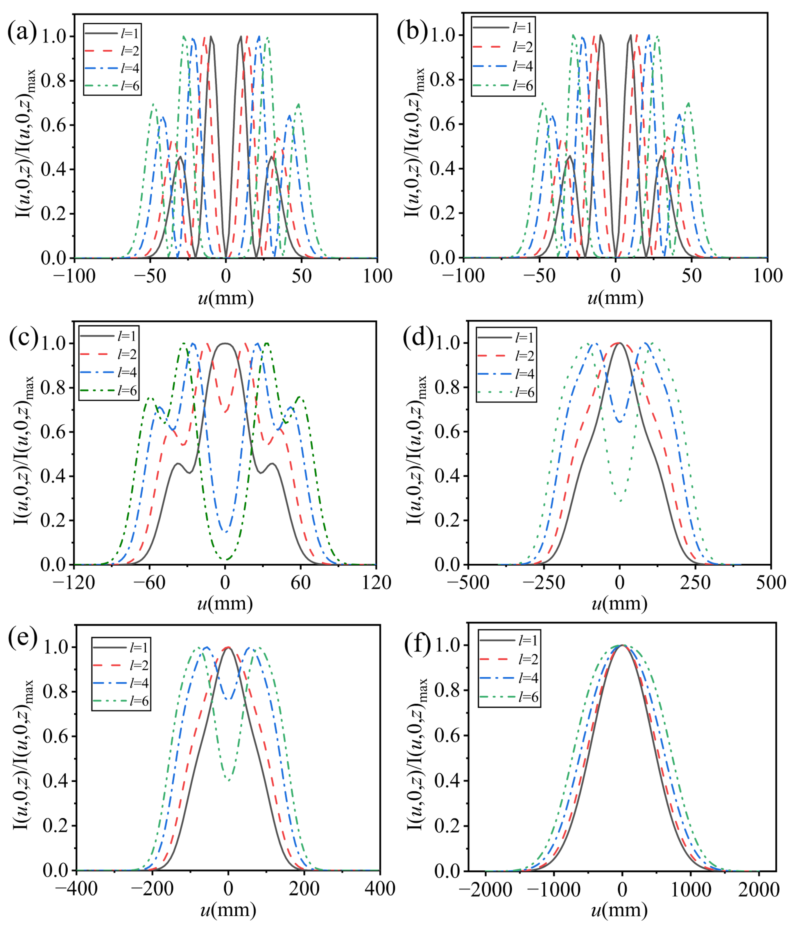
Based on Equations (11)–(13) and (22), the intensity distributions of the PCLG beam for the forward and reverse transmission can be numerically evaluated, respectively. The default parameter values required were chosen to be λ = 632.8 nm, w0 =20 mm, σg = 20 mm, p = 2, l = 1, C n 2 = 0.5 × 10 15 m 2 / 3 , l0 = 7 mm, nz = 0.2, and Lz = 402.4 μm, unless otherwise specified. Figure 1 and Figure 2 show the cross-sectional lines of the normalized intensity of a PCLG beam with different initial coherence width values at different propagation distances for forward and reverse transmission, respectively. From Figure 1 and Figure 2, the evolution trend of the intensity distributions of PCLG beams are the same in both forward and reverse transmission. It is evident that the beam profile eventually evolves from an LG beam shape to a Gaussian beam shape as the propagation distance increases and the beam waist of the Gaussian beam is larger when the initial transverse coherence width is small at the far field. Compared to reverse transmission, the evolution speed for forward transmission is slower, owing to the different transmission matrix element B in Equations (11) and (12). For reverse transmission, the PCLG beams first pass through a thin plasma layer and then through atmospheric turbulence. When passing through the plasma, it has a significant impact on the beams, causing it to diverge quickly and evolve into a Gaussian-like intensity distribution.
Moreover, the initial transverse coherence width σg impacts the evolution speed of the beam enormously—the smaller the initial transverse coherence width, the faster the beam evolves into a Gaussian beam profile. From Figure 1 and Figure 2c, the LG beam shape evolves into a Gaussian beam at a propagation distance z = 5 km when the initial transverse coherence width σg is 10 mm for both forward and reverse transmission. However, the LG beam is still evolving into a Gaussian beam when σg = infinity.
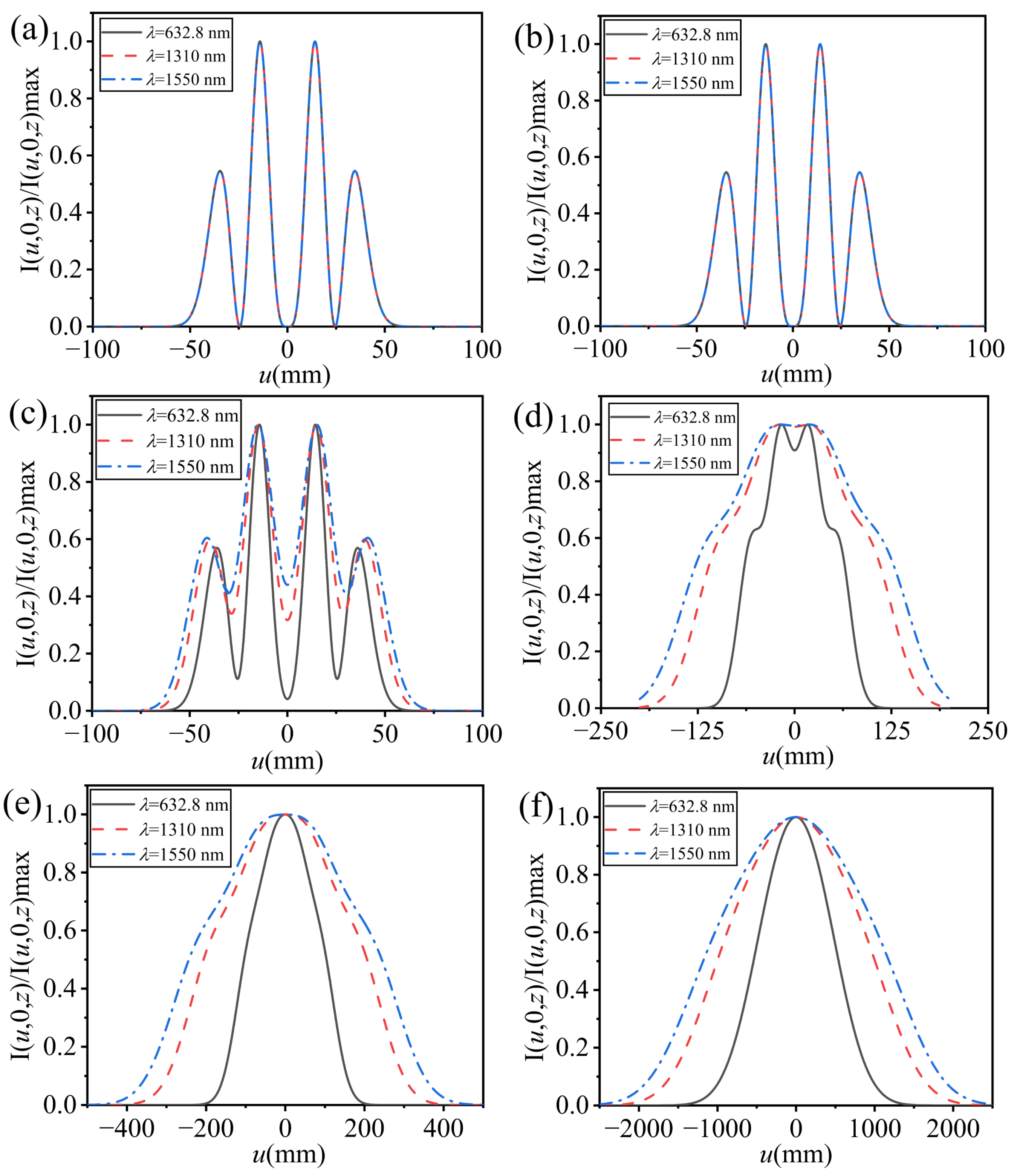
Figure 3 and Figure 4 show the cross-sectional lines of the normalized intensity of a PCLG beam with different beam orders and wavelengths at different propagation distances for forward and reverse transmission, respectively. Due to the influence of plasma, the intensity profile of PCLG beams at z = 5 km for forward transmission is similar to that at z = 1.5 km for reverse transmission in Figure 3, which indicates that the intensity evolution speed for forward transmission is slow. In addition, the PCLG beams with high beam orders have stronger anti-turbulence ability. From Figure 4, wavelength also affects the propagation properties of PCLG beams in bidirectional atmospheric turbulence and plasma. The PCLG beam with longer wavelength first evolve into Gaussian distributions under the same conditions. Consequently, the PCLG beam profile with a higher beam order and a shorter wavelength evolves into a Gaussian beam profile at a slower rate, with the forward transmission of the beam evolving more slowly than the reverse transmission. From Figure 1, Figure 2, Figure 3 and Figure 4, the results indicate that the evolution speed of the beam for reverse transmission is faster than that for forward transmission under the same conditions, implying that the plasma plays a major role in the bidirectional propagation of the beam. Evidently, a PCLG beam with a larger transverse coherence width, higher beam order, and shorter wavelength exhibits stronger resistance to turbulence.

3. Effective Beam Width

The effective beam width of a PCLG beam through atmospheric turbulence and plasma in the x- or y-direction at plane z can be expressed as follows [44]:
W ρ z ( z ) = ρ 2 I ( x , y , z ) d x d y I ( x , y , z ) d x d y , ρ = ( x , y ) .
Based on Equation (13) and I(x, y, z) = W(x, y, x, y; z), Equation (23) can be derived as follows:
W x z ( z ) = W y z ( z ) = A 1 ( z ) A 2 ( z ) ,
where
A 1 ( z ) = ( 1 λ | B | ) 2 1 2 4 p + 2 l ( p ! ) 2 π 3 M 3 M 2 M 1 ( 1 2 M 2 2 2 M 2 M 1 w 0 2 ) ( l + 2 p ) / 2 ( 2 2 w 0 ) l + 2 p    × m = 0 p n = 0 l h = 0 p s = 0 l d 2 h + l s c 1 ( 2 m + l n ) / 2 c 2 d / 2 d 1 2 p 2 h + s e 1 ( 2 p 2 m + n ) / 2    × e 2 d 1 / 2 f 1 ( 2 h + l s d ) / 2 f 2 ( 2 m + l n + d 2 c 1 2 c 2 ) / 2 g 1 ( 2 p 2 h + s d 1 ) / 2 g 2 ( 2 p 2 m + n + d 1 2 e 1 2 e 2 ) / 2    × ( i n ) * i s ( p m ) ( l n ) ( p h ) ( l s ) ( 2 h + l s d ) ( 2 p 2 h + s d 1 ) ( 1 ) c 1 + c 2 + e 1 + e 2 + f 1 + f 2 + g 1 + g 2    × ( 2 m + l n ) ! c 1 ! ( 2 m + l n 2 c 1 ) ! d ! c 2 ! ( d 2 c 2 ) ! ( 2 p 2 m + n ) ! e 1 ! ( 2 p 2 m + n 2 e 1 ) !    × d 1 ! e 2 ! ( d 1 2 e 2 ) ! ( 2 h + l s d ) ! f 1 ! ( 2 h + l s d 2 f 1 ) !    × ( 2 m + l n + d 2 c 1 2 c 2 ) ! f 2 ! ( 2 m + l n + d 2 c 1 2 c 2 2 f 2 ) ! ( 2 p 2 h + s d 1 ) ! g 1 ! ( 2 p 2 h + s d 1 2 g 1 ) !    × ( 2 p 2 m + n + d 1 2 e 1 2 e 2 ) ! g 2 ! ( 2 p 2 m + n + d 1 2 e 1 2 e 2 2 g 2 ) ! ( 2 i ) 4 c 1 + 4 c 2 + 4 e 1 + 4 e 2 d d 1 6 p 3 l + 2 f 1 + 2 f 2 + 2 g 1 + 2 g 2 2    × ( 1 M 2 ) d + d 1 2 c 1 2 c 2 2 e 1 2 e 2 ( 2 2 w 0 ) 2 c 1 2 e 1    ( 2 i k B M 1 2 w 0 2 2 M 1 ) 2 h + l s d 2 f 1 ( 2 i k B M 1 2 w 0 2 2 M 1 ) 2 p 2 h + s d 1 2 g 1    ( 2 σ g 2 M 1 2 w 0 2 2 M 1 + 4 π 2 T k 2 z 3 M 1 2 w 0 2 2 M 1 ) d + d 1 2 e 2 2 c 2    × ( k M 2 [ 1 M 1 ( 1 2 σ g 2 + π 2 T k 2 z 3 ) 1 B 1 B ] ) 2 m + l n + d 2 c 1 2 c 2 2 f 2    × ( k M 2 [ 1 M 1 ( 1 2 σ g 2 + π 2 T k 2 z 3 ) 1 B 1 B ] ) 2 p 2 m + n + d 1 2 e 1 2 e 2 2 g 2    × ( 1 M 3 ) l f 1 c 1 c 2 f 2 + 2 p e 1 e 2 g 1 g 2 + 1    × H 2 h + 2 m + 2 l s n 2 f 1 2 c 1 2 c 2 2 f 2 + 2 ( 0 ) H 4 p 2 h 2 m + s + n 2 e 1 2 e 2 2 g 1 2 g 2 ( 0 ) ,
A 2 ( z ) = ( 1 λ | B | ) 2 1 2 4 p + 2 l ( p ! ) 2 π 3 M 3 M 2 M 1 ( 1 2 M 2 2 2 M 2 M 1 w 0 2 ) ( l + 2 p ) / 2 ( 2 2 w 0 ) l + 2 p    × m = 0 p n = 0 l h = 0 p s = 0 l d 2 h + l s c 1 ( 2 m + l n ) / 2 c 2 d / 2 d 1 2 p 2 h + s e 1 ( 2 p 2 m + n ) / 2    × e 2 d 1 / 2 f 1 ( 2 h + l s d ) / 2 f 2 ( 2 m + l n + d 2 c 1 2 c 2 ) / 2 g 1 ( 2 p 2 h + s d 1 ) / 2 g 2 ( 2 p 2 m + n + d 1 2 e 1 2 e 2 ) / 2    × ( i n ) * i 2 ( p m ) ( l n ) ( p h ) ( l s ) ( 2 h + l s d ) ( 2 p 2 h + s d 1 ) ( 1 ) c 1 + c 2 + e 1 + e 2 + f 1 + f 2 + g 1 + g 2    × ( 2 m + l n ) ! c 1 ! ( 2 m + l n 2 c 1 ) ! d ! c 2 ! ( d 2 c 2 ) ! ( 2 p 2 m + n ) ! e 1 ! ( 2 p 2 m + n 2 e 1 ) !    × d 1 ! e 2 ! ( d 1 2 e 2 ) ! ( 2 h + l s d ) ! f 1 ! ( 2 h + l s d 2 f 1 ) !    × ( 2 m + l n + d 2 c 1 2 c 2 ) ! f 2 ! ( 2 m + l n + d 2 c 1 2 c 2 2 f 2 ) ! ( 2 p 2 h + s d 1 ) ! g 1 ! ( 2 p 2 h + s d 1 2 g 1 ) !    × ( 2 p 2 m + n + d 1 2 e 1 2 e 2 ) ! g 2 ! ( 2 p 2 m + n + d 1 2 e 1 2 e 2 2 g 2 ) ! ( 2 i ) 4 c 1 + 4 c 2 + 4 e 1 + 4 e 2 d d 1 6 p 3 l + 2 f 1 + 2 f 2 + 2 g 1 + 2 g 2    × ( 1 M 2 ) d + d 1 2 c 1 2 c 2 2 e 1 2 e 2 ( 2 2 w 0 ) 2 c 1 2 e 1 ( 1 M 3 ) l f 1 c 1 c 2 f 2 + 2 p e 1 e 2 g 1 g 2    × ( 2 σ g 2 M 1 2 w 0 2 q 2 M 1 + 4 π 2 T k 2 z 3 M 1 2 w 0 2 q 2 M 1 ) d + d 1 2 e 2 2 c 2    × ( 2 i k B M 1 2 w 0 2 q 2 M 1 ) 2 h + l s d 2 f 1 ( 2 i k B M 1 2 w 0 2 2 M 1 ) 2 p 2 h + s d 1 2 g 1    × ( k M 2 [ 1 M 1 ( 1 2 σ g 2 + π 2 T k 2 z 3 ) 1 B 1 B ] ) 2 m + l n + d 2 c 1 2 c 2 2 f 2    × ( k M 2 [ 1 M 1 ( 1 2 σ g 2 + π 2 T k 2 z 3 ) 1 B 1 B ] ) 2 p 2 m + n + d 1 2 e 1 2 e 2 2 g 2    × H 2 h + 2 m + 2 l s n 2 f 1 2 c 1 2 c 2 2 f 2 ( 0 ) H 4 p 2 h 2 m + s + n 2 e 1 2 e 2 2 g 1 2 g 2 ( 0 ) ,
where
M 3 = k 2 4 B 2 M 1 + k 2 4 M 2 [ 1 M 1 ( 1 2 σ g 2 + π 2 T k 2 z 3 ) 1 B + 1 B ] 2 .
Figure 5 shows the effective beam width of the PCLG beam for forward and reverse transmission, influenced by beam parameters such as the beam order, transverse coherence width, and wavelength. The effective beam width expands with the increase in propagation distance, and is linearly related to the propagation distance when z > 5 km. As the beam order and wavelength of the beam increase or the transverse coherence width decreases, the diffusion of the PCLG beam accelerates in atmospheric turbulence and plasma. And the initial effective beam width of a PCLG beam with higher beam order is greater than that of a PCLG beam with lower order when z = 0. It is evident that the beam order, transverse coherence width, and wavelength affect the effective beam width of the PCLG beam. The effective beam width for reverse transmission is larger than that for forward transmission at the same propagation distance, which illustrates that the PCLG beam rapidly diverges for reverse transmission due to propagating the plasma first. Compared to the beam order, the transverse coherence width and wavelength have a greater impact on the effective width of PCLG beam for both forward and reverse transmission. Consequently, the effective beam width of a PCLG beam impacted by atmospheric turbulence and plasma can be mitigated by selecting suitable values for the beam order, wavelength, and transverse coherence width.

4. M2 Factor

The M2 factor of a PCLG beam bidirectionally propagating in atmospheric turbulence and plasma can be obtained by adopting the methods mentioned in [46] and introducing the sum vector notations ρs= (ρ1 + ρ2)/2 and rs = (r1 + r2)/2. Consequently, Equations (8) and (9) can be rewritten as follows:
W ( r s , 1 A ( ρ d + B k κ d ) ; 0 ) = 1 2 4 p + 2 l ( p ! ) 2 m = 0 p n = 0 l h = 0 p s = 0 l ( i n ) * i s ( p m ) ( l n ) ( p h ) ( l s ) × H 2 m + l n ( 2 w 0 r s x + 2 2 w 0 1 A ( ρ d x + B k κ d x ) ) H 2 h + l s ( 2 w 0 r s x 2 2 w 0 1 A ( ρ d x + B k κ d x ) ) × exp [ 1 w 0 2 [ r s x + 1 2 1 A ( ρ d x + B k κ d x ) ] 2 1 w 0 2 [ r s x 1 2 1 A ( ρ d x + B k κ d x ) ] 2 1 A 2 ( ρ d x + B k κ d x ) 2 2 σ g 2 ] × H 2 p 2 m + n ( 2 w 0 r s y + 2 2 w 0 1 A ( ρ d y + B k κ d y ) ) H 2 p 2 h + s ( 2 w 0 r s y 2 2 w 0 1 A ( ρ d y + B k κ d y ) ) × exp [ 1 w 0 2 [ r s y + 1 2 1 A ( ρ d y + B k κ d y ) ] 2 1 w 0 2 [ r s x 1 2 1 A ( ρ d y + B k κ d y ) ] 2 1 A 2 ( ρ d y + B k κ d y ) 2 2 σ g 2 ] .
W ( ρ s , ρ d ; z ) = ( k 2 π B ) 2 W ( r s , 1 A ( ρ d + B k κ d ) ; 0 )      × exp [ i k B ( B k r s κ d 1 A B k ρ s κ d + D ρ s ρ d 1 A ρ s ρ d )      H ( ρ d , 1 A ( ρ d + B k κ d ) , z ) ] d 2 r s d 2 κ d .
where κd = (κdx, κdy) denotes the position vector in the spatial frequency domain.
The WDF of a partially coherent beam through atmospheric turbulence can be expressed in terms of the CSD function as follows [47]:
h ( ρ s , θ , z ) = k 2 4 π 2 W ( ρ s , ρ d ; z ) exp ( i k θ ρ d ) d 2 ρ d ,
where θ = (θx, θy) denotes the angle between the vector of interest and the z-direction, and x and y denote the wave vector components along the x- and y-axis, respectively.
Substituting Equations (28) and (29) into Equation (30), the WDF can be determined as follows:
h ( ρ s , θ , z ) = k 2 w 0 2 32 π 3 A 2 1 2 2 p + l ( p ! ) 2 m = 0 p n = 0 l h = 0 p s = 0 l    × ( i n ) * i s ( p m ) ( l n ) ( p h ) ( l s ) ( 2 m + l n ) ! ( 2 p 2 m + n ) !    × exp [ i 1 A ρ s κ d i k θ ρ d a κ d 2 b ρ d 2 + c ρ d κ d + i e ρ s ρ d H ( ρ d , 1 A ( ρ d + B k κ d ) , z ) ]    × [ i w 0 2 2 κ d x 2 2 w 0 1 A ( ρ d x + B k κ d x ) ] 2 h s 2 m + n    × L 2 m + l n 2 h s 2 m + n [ 1 w 0 2 1 A 2 ρ d x 2 + 2 1 w 0 2 1 A 2 B k κ d x ρ d x + ( 1 w 0 2 1 A 2 B 2 k 2 + w 0 2 4 ) κ d x 2 ]    × [ i w 0 2 2 κ d y 2 2 w 0 1 A ( ρ d y + B k κ d y ) ] 2 h + s + 2 m n    × L 2 p 2 m + n 2 h + s + 2 m n [ 1 w 0 2 1 A 2 ρ d y 2 + 2 1 w 0 2 1 A 2 B k κ d y ρ d y + ( 1 w 0 2 1 A 2 B 2 k 2 + w 0 2 4 ) κ d y 2 ] d κ d x d κ d y d ρ d x d ρ d y ,
where
a = ( 1 A 2 1 ε 2 B 2 k 2 + w 0 2 8 ) ,   b = 1 A 2 1 ε 2 ,   c = 2 1 A 2 1 ε 2 B k ,   e = k B ( 1 A D ) .
In above derivations, the following integral formula can be used [45]:
exp ( x 2 ) H m ( x + y ) H ( x + z ) d x = 2 n π m ! z n m L m n m ( 2 y z ) .
Based on the second-order moments of the WDF, the M2 factor of the beams can be defined as follows:
M 2 ( z ) = k ( ρ s 2 θ 2 ρ s θ 2 ) 1 / 2 = k [ ( x 2 + y 2 ) ( θ x 2 + θ y 2 ) ( x θ x + y θ y ) 2 ] 1 / 2 .
The moments of the order n1 + n2 + m1 + m2 of the WDF for three-dimensional beams can be expressed as follows:
x n 1 y n 2 θ x m 1 θ y m 2 = 1 p x n 1 y n 2 θ x m 1 θ y m 2 h ( ρ s , θ , z ) d 2 ρ s d 2 θ ,
where
P = h ( ρ s , θ , z ) d ρ s d θ .
Substituting Equation (31) into Equation (35) and using the formulas as follows [45]:
δ ( s ) = 1 2 π exp ( i s x ) d x ,
δ n ( s ) = 1 2 π ( i x ) n exp ( i s x ) d x ( n = 1 , 2 ) ,
f ( x ) δ n ( s ) d x = ( 1 ) n f n ( 0 ) ,
we obtain the following:
P = w 0 2 π A 2 2 1 2 2 p + l ( p ! ) 2 m = 0 p n = 0 l h = 0 p s = 0 l ( i n ) * i s ( p m ) ( l n ) ( p h ) ( l s ) ( 2 m + l n ) ! ( 2 p 2 m + n ) ! ,
ρ s 2 = ρ s x 2 + ρ s y 2 = A π w 0 2 P 1 2 2 p + l ( p ! ) 2 m = 0 p n = 0 l h = 0 p s = 0 l × ( i n ) * i s ( p m ) ( l n ) ( p h ) ( l s ) ( 2 m + l n ) ! ( 2 p 2 m + n ) ! × { 2 [ a A 2 + π 2 T k 2 z 3 1 A 2 B 2 k 2 A 2 ] + [ ( 1 w 0 2 1 A 2 B 2 k 2 + w 0 2 4 ) A 2 ] ( 2 p + l ) } ,
θ 2 = θ x 2 + θ y 2 = A π w 0 2 P 1 2 2 p + l ( p ! ) 2 m = 0 p n = 0 l h = 0 p s = 0 l × ( i n ) * i s ( p m ) ( l n ) ( p h ) ( l s ) ( 2 m + l n ) ! ( 2 p 2 m + n ) ! × { 2 [ a A 2 e 2 1 k 2 + b 1 k 2 c A e 1 k 2 + π 2 T k 2 z 3 ( 1 A 2 + 2 1 A B k e + B 2 k 2 e 2 + 1 A + B k e + 1 ) 1 k 2 ] + [ 1 w 0 2 1 A 2 1 k 2 + 2 1 w 0 2 1 A 2 B k A e 1 k 2 + ( 1 w 0 2 1 A 2 B 2 k 2 + w 0 2 4 ) A 2 e 2 1 k 2 ] ( 2 p + l ) } ,
ρ s θ = ρ s x θ x + ρ s y θ y = A π w 0 2 P 1 2 2 p + l ( p ! ) 2 m = 0 p n = 0 l h = 0 p s = 0 l × ( i n ) * i s ( p m ) ( l n ) ( p h ) ( l s ) ( 2 m + l n ) ! ( 2 p 2 m + n ) ! × { [ 2 a A 2 e 1 k c 1 k A + π 2 T k 2 z 3 [ 2 1 A B k 2 + 2 B 2 k 2 e 1 k + B k 1 k ] ] + [ 1 w 0 2 1 A 2 B k A 1 k + ( 1 w 0 2 1 A 2 B 2 k 2 + w 0 2 4 ) A 2 e 1 k ] ( 2 p + l ) } .
Substituting Equations (41)–(43) into Equation (34), the M2 factor of the PCLG beams in the receiving plane can be expressed as follows:
M 2 ( z ) = k ( ρ s 2 θ 2 ρ s θ 2 ) 1 / 2 = k ( { A π w 0 2 P 1 2 2 p + l ( p ! ) 2 m = 0 p n = 0 l h = 0 p s = 0 l ( i n ) * i s ( p m ) ( l n ) ( p h ) ( l s ) ( 2 m + l n ) ! ( 2 p 2 m + n ) ! × [ 2 ( a A 2 + π 2 T k 2 z 3 1 A 2 B 2 k 2 A 2 ) + A 2 ( 1 w 0 2 1 A 2 B 2 k 2 + w 0 2 4 ) ( 2 p + l ) ] } × { A π w 0 2 P 1 2 2 p + l ( p ! ) 2 m = 0 p n = 0 l h = 0 p s = 0 l ( i n ) * i s ( p m ) ( l n ) ( p h ) ( l s ) ( 2 m + l n ) ! ( 2 p 2 m + n ) ! × { 2 [ a A 2 e 2 1 k 2 + b 1 k 2 c A e 1 k 2 + π 2 T k 2 z 3 ( 1 A 2 + 2 1 A B k e + B 2 k 2 e 2 + 1 A + B k e + 1 ) 1 k 2 ] + [ 1 w 0 2 1 A 2 1 k 2 + 2 1 w 0 2 1 A 2 B k A e 1 k 2 + ( 1 w 0 2 1 A 2 B 2 k 2 + w 0 2 4 ) A 2 e 2 1 k 2 ] ( 2 p + l ) } } { A π w 0 2 P 1 2 2 p + l ( p ! ) 2 m = 0 p n = 0 l h = 0 p s = 0 l × ( i n ) * i s ( p m ) ( l n ) ( p h ) ( l s ) ( 2 m + l n ) ! ( 2 p 2 m + n ) ! × { [ 2 a A 2 e 1 k c 1 k A + π 2 T k 2 z 3 [ 2 1 A B k 2 + 2 B 2 k 2 e 1 k + B k 1 k ] ] + [ 1 w 0 2 1 A 2 B k A 1 k + ( 1 w 0 2 1 A 2 B 2 k 2 + w 0 2 4 ) A 2 e 1 k ] ( 2 p + l ) } } 2 ) 1 / 2 .
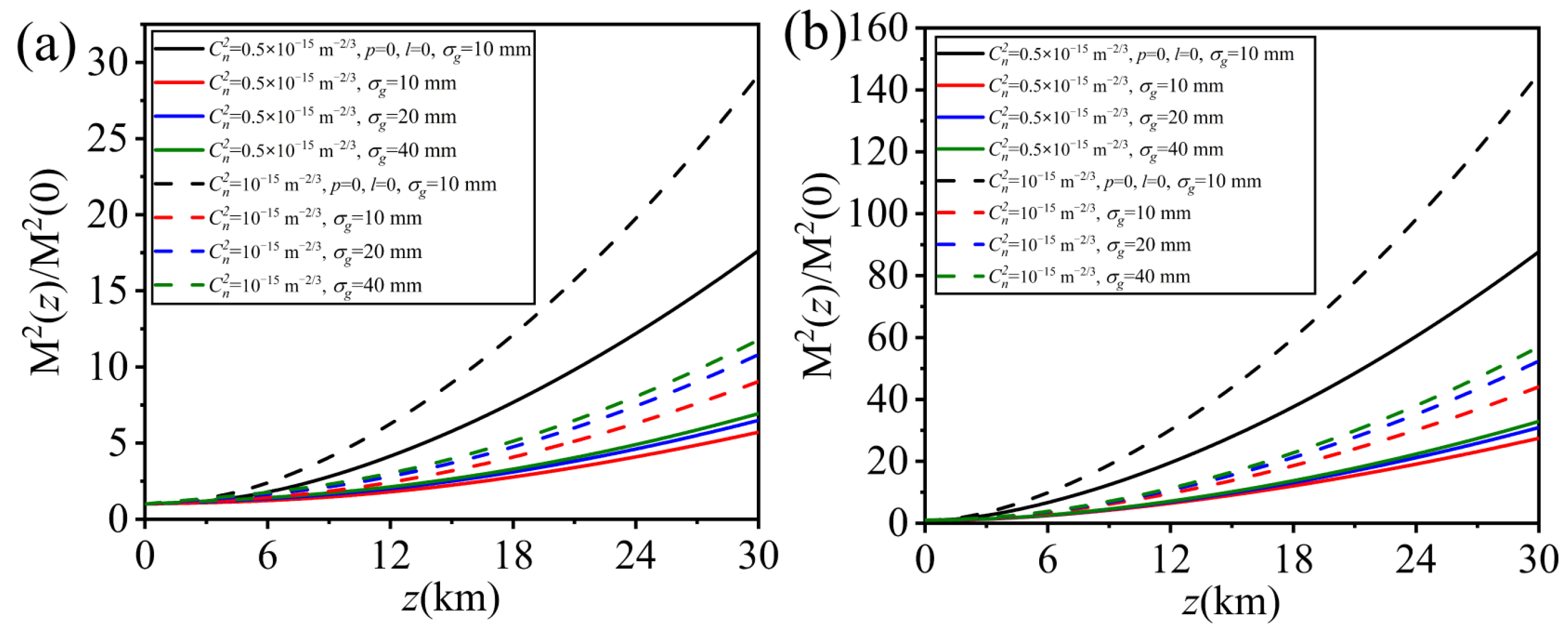
The variations in the normalized M2 factor of a PCLG beam with different structural constants of the atmospheric turbulence and beam orders when w0 = 40 mm for forward and reverse transmission are shown in Figure 6. This indicates that the normalized M2 factor of a PCLG beam increases with the strength of the atmospheric turbulence and propagation distance. The normalized M2 factor of a PCLG beam with higher beam order is smaller than that of a beam with lower beam order. When p = l = 0, the PCLG beam degrades into a Gaussian beam. The normalized M2 factor of the PCLG beam is smaller than that of the Gaussian beam under the same conditions. Consequently, a partially coherent beam has advantages over a fully coherent beam in terms of turbulence resistance. Additionally, the normalized M2 factor of the PCLG beam for forward transmission is smaller than that for reverse transmission.
Figure 7 and Figure 8 show the normalized M2 factor of a PCLG beam with different wavelengths and transverse coherence widths under two atmospheric turbulence intensities for forward and reverse transmission, respectively. The beam parameters were set to p = 3, l = 2, and w0 = 40 mm. The normalized M2 factor of a PCLG beam increases as the wavelength decreases and the transverse coherence width increases. This indicates that a PCLG beam with a larger wavelength and lower transverse coherence width is less affected by atmospheric turbulence and plasma. The normalized M2 factor of a PCLG beam for reverse transmission is larger than that for forward transmission.
From Figure 6, Figure 7 and Figure 8, the normalized M2 factor of a PCLG beam for forward and reverse transmission increases with propagation distance. The initial normalized M2 factor of a PCLG beam is small, and due to the presence of atmospheric turbulence and plasma, the beam quality rapidly deteriorated during propagation. With an increase in the structural constant and transverse coherence width or a decrease in the beam order and wavelength, the rate of increase in the normalized M2 factor of a PCLG beam is rapid. Compared with forward transmission, the normalized M2 factor of a PCLG beam for reverse transmission is always larger. This demonstrates that the influence of the plasma on the normalized M2 factor of a PCLG beam is greater than that of atmospheric turbulence.

5. Conclusions

In conclusion, the normalized intensity distribution, effective beam width, and M2 factor of PCLG beams propagating bidirectionally in atmospheric turbulence and plasma were investigated both theoretically and numerically. The results demonstrate the influence of beam parameters—such as the beam order, transverse coherence width, and wavelength—on the intensity distribution, effective beam width, and M2 factor of the PCLG beams. And the atmospheric turbulence and plasma affected the intensity distribution enormously, and the effective beam width and M2 factor of the PCLG beams increased with increasing propagation distance. The impact of PCLG beams propagation for reverse transmission is greater than in forward transmission. These findings should prove to be useful for free-space optical communication applications.

Author Contributions

Conceptualization, H.Z. and Y.Y.; methodology, Y.Z. (Yuelei Zhang) and Y.Z. (Yuanhao Zhao); software, Y.Z. (Yuelei Zhang) and L.Y.; validation, L.Y. and Y.Z. (Yuanhao Zhao); formal analysis, Y.Z. (Yuelei Zhang) and Y.G.; writing—original draft preparation, Y.Z. (Yuelei Zhang) and Y.G.; writing—review and editing, Y.Z. (Yuelei Zhang) and Y.G.; supervision, Y.C., Y.Y. and Y.G.; funding acquisition, Y.C., Y.Y. and Y.G. All authors have read and agreed to the published version of the manuscript.

Funding

National Key Research and Development Program of China (2022YFA1404800), National Natural Science Foundation of China (12192254, 12174227, 12474295, 92250304, W2441005), and Key Research and Development Program of Shandong Province (2024JMRH0105).

Institutional Review Board Statement

Not applicable.

Informed Consent Statement

Not applicable.

Data Availability Statement

Data are contained within the article.

Conflicts of Interest

The authors declare no conflicts of interest.

References

  1. Yuan, Y.; Zhang, J.; Dang, J.; Zheng, W.; Zheng, G.; Fu, P.; Qu, J.; Hoenders, B.; Zhao, Y.; Cai, Y. Enhanced fiber-coupling efficiency via high-order partially coherent flat-topped beams for free-space optical communications. Opt. Express 2022, 30, 5634–5643. [Google Scholar] [CrossRef]
  2. Zhang, J.; Wang, Z.; Cheng, B.; Wang, Q.; Wu, B.; Shen, X.; Zheng, L.; Xu, Y.; Lin, Q. Atom cooling by partially spatially coherent lasers. Phys. Rev. A 2013, 88, 023416. [Google Scholar] [CrossRef]
  3. Pesonen, H.; Halder, A.; Huusko, J.; Friberg, A.; Setala, T.; Turunen, J. Spatial coherence effects in second-harmonic generation of scalar light fields. J. Optics-UK 2021, 23, 035501. [Google Scholar] [CrossRef]
  4. Cai, Y.; Peschel, U. Second-harmonic generation by an astigmatic partially coherent beam. Opt. Express. 2007, 15, 15480–15492. [Google Scholar] [CrossRef] [PubMed]
  5. Domanski, A.; Cieslak, R.; Karpierz, M.; Budaszewski, D.; Wolinski, T. Efficiency of second harmonic generation for partially coherent light in anisotropic crystals. Open Phys. 2008, 6, 628–633. [Google Scholar] [CrossRef]
  6. Kato, Y.; Mima, K.; Miyanaga, N.; Arinaga, S.; Kitagawa, Y.; Nakatsuaka, M.; Yamanaka, C. Random phasing of high-power lasers for uniform target acceleration and plasma-instability suppression. Phys. Rev. Lett. 1984, 53, 1057–1060. [Google Scholar] [CrossRef]
  7. Deng, H.; Wu, P.; Tao, Z.; Li, X.; Li, Y.; Ruizhong, R.; Ren, Y. Scintillation of Computational Ghost Imaging with a Finite Bucket Detector through Atmospheric Turbulence. Photonics. 2023, 10, 542. [Google Scholar] [CrossRef]
  8. Luo, M.; Zhu, W.; Zhao, D. Ghost imaging and its visibility with partially coherent elliptical Gaussian Schell-model beams. Phy. Lett. A 2015, 379, 2789–2794. [Google Scholar] [CrossRef]
  9. Dawkins, R.; Hong, M.; You, C.; Magana-Loaiza, O. The quantum Gaussian–Schell model: A link between classical and quantum optics. Opt. Lett. 2024, 49, 4242–4245. [Google Scholar] [CrossRef]
  10. Alkelly, A.A.; Khaled, M.A.H.; Hassan, L.F. Propagation of Partially Coherent Flat-Topped Vortex Hollow Beams in Anisotropic Turbulent Plasma. Int. J. Opt. 2022, 2022, 7798053. [Google Scholar] [CrossRef]
  11. Wu, Z.; Feng, Z.; Ye, S.; Song, B.; Wei, R.; Yu, C. Beam properties of a partially coherent beam propagating horizontally in atmospheric turbulence. Photonics 2023, 10, 477. [Google Scholar] [CrossRef]
  12. Huang, Y.; Zhang, B. Turbulence distance for laser beams propagating through non-Kolmogorov turbulence. J. Opt. Soc. Am. A 2013, 30, 2339–2346. [Google Scholar] [CrossRef]
  13. Li, Y.; Wu, Z. Characteristics of a partially coherent Gaussian Schell-model beam propagating in slanted atmospheric turbulence. Chinese Phys. B. 2012, 21, 054203. [Google Scholar] [CrossRef]
  14. Ji, X.; Lü, B. Turbulence-induced quality degradation of partially coherent beams. Opt. Commun. 2005, 251, 231–236. [Google Scholar] [CrossRef]
  15. Zhou, Z.; Qu, J. Self-splitting and propagation factors of a superimposed Hermite-Gaussian correlated Schell-model beam in turbulent atmosphere. Results Phys. 2021, 28, 104609. [Google Scholar] [CrossRef]
  16. Wang, C.; Liu, L.; Liu, L.; Yu, J.; Wang, F.; Cai, Y.; Peng, X. Second-order statistics of a Hermite-Gaussian correlated Schell-model beam carrying twisted phase propagation in turbulent atmosphere. Opt. Express 2023, 31, 13255–13268. [Google Scholar] [CrossRef] [PubMed]
  17. Li, J.; Suo, Q.; Chen, L. Analysis to beam quality of partially coherent flat-topped vortex beams propagating through atmospheric turbulence. Optik 2016, 127, 11342–11348. [Google Scholar] [CrossRef]
  18. Zhang, Y.; Wang, J.; Qian, X.; Zhu, W.; Li, J. Orbital angular momentum evolution of twisted multi-Gaussian Schell model beams in anisotropic turbulence. Opt. Commun. 2022, 520, 128454. [Google Scholar] [CrossRef]
  19. Hu, J.; Ji, X.; Wang, H.; Deng, Y.; Li, X.; Wang, T.; Zhang, H. Influence of Kerr nonlinearity on propagation characteristics of twisted Gaussian Schell-model beams. Opt. Express 2021, 29, 23393–23407. [Google Scholar] [CrossRef]
  20. Xu, Y.; Xu, Y.; Wang, T. Evolution properties of a partially coherent twisted laguerre-gaussian pulsed beam propagating through anisotropic atmospheric turbulence. Photonics 2022, 9, 707. [Google Scholar] [CrossRef]
  21. Zhong, Y.; Cui, Z.; Shi, J.; Qu, J. Propagation properties of partially coherent Laguerre–Gaussian beams in turbulent atmosphere. Opt. Laser Technol. 2011, 43, 741–747. [Google Scholar] [CrossRef]
  22. Huang, K.; Xu, Y.; Li, Y. Average Intensity of a Laguerre–Gaussian Vector Vortex Beam through Inhomogeneous Atmospheric Turbulence. Photonics 2023, 10, 1189. [Google Scholar] [CrossRef]
  23. Wang, Z.; Zhang, Z.; Lin, Q. Atom interferometers manipulated through the toroidal trap realized by the interference patterns of Laguerre-Gaussian beams. Eur. Phys. J. D 2009, 53, 127–131. [Google Scholar] [CrossRef]
  24. Bradshaw, D.; Andrews, D. Interactions between spherical nanoparticles optically trapped in Laguerre–Gaussian modes. Opt. Lett. 2005, 30, 3039–3041. [Google Scholar] [CrossRef] [PubMed]
  25. Arlt, J.; Hitomi, T.; Dholakia, K. Atom guiding along Laguerre-Gaussian and Bessel light beams. Appl. Phys. B 2000, 71, 549–554. [Google Scholar] [CrossRef]
  26. Rhodes, D.; Gherardi, D.; Livesey, J.; Mcgloin, D.; Melvilie, H.; Freegarde, T.; Dholakia, K. Atom guiding along high order Laguerre–Gaussian light beams formed by spatial light modulation. J. Mod. Optic. 2006, 53, 547–556. [Google Scholar] [CrossRef]
  27. Kuga, T.; Torii, Y.; Shiokawa, N.; Hirano, T. Novel optical trap of atoms with a doughnut beam. Phys. Rev. Lett. 1997, 78, 4713–4716. [Google Scholar] [CrossRef]
  28. Song, H.; Pae, K.; Won, J.; Song, J.; Lee, S.; Kim, C.; Ryu, C.; Bang, W.; Nam, C. Characteristics of electron beams accelerated by parallel and antiparallel circularly polarized Laguerre–Gaussian laser pulses. Appl. Phys. B 2023, 129, 56. [Google Scholar] [CrossRef]
  29. Cai, Y.; He, S. Propagation of a Laguerre–Gaussian beam through a slightly misaligned paraxial optical system. Appl. Phys. B 2006, 84, 493–500. [Google Scholar] [CrossRef]
  30. Wang, H.; Wang, H.; Xu, Y.; Qian, X. Intensity and polarization properties of the partially coherent Laguerre–Gaussian vector beams with vortices propagating through turbulent atmosphere. Opt. Laser Technol. 2014, 56, 1–6. [Google Scholar] [CrossRef]
  31. Alkelly, A.; Khaled, M.; Hassan, L. Angular width and beam quality of a partially coherent standard Laguerre–Gaussian vortex beam in turbulent plasma. J. Opt. Soc. Am. A 2024, 41, 45–53. [Google Scholar] [CrossRef] [PubMed]
  32. Lv, C.; Cui, Z.; Han, Y. Light propagation characteristics of turbulent plasma sheath surrounding the hypersonic aerocraft. Chinese Phys. B 2019, 28, 074203. [Google Scholar] [CrossRef]
  33. Li, J.; Yang, S.; Guo, L. Propagation characteristics of Gaussian beams in plasma sheath turbulence. IET Microw. Antenna. P 2017, 11, 280–286. [Google Scholar] [CrossRef]
  34. Hassan, L.; Alkelly, A.; Khaled, M. Polarization and coherence properties of a partially coherent elegant Laguerre–Gaussian vortex beam in turbulent plasma. J. Appl. Phys. 2024, 135, 193107. [Google Scholar] [CrossRef]
  35. Wang, X.; Zhang, H.; Gao, Y.; Wei, D.; Cai, Y.; Yuan, Y. Distribution of intensity and M2 factor for a partially coherent flat-topped beam in bidirectional turbulent atmosphere and plasma connection. Opt. Express 2024, 32, 5982–5995. [Google Scholar] [CrossRef]
  36. Li, J.; Yang, S.; Guo, L.; Cheng, M. Anisotropic power spectrum of refractive-index fluctuation in hypersonic turbulence. Appl. Optics. 2016, 55, 9137–9144. [Google Scholar] [CrossRef]
  37. Li, J.; Li, J.; Guo, L.; Cheng, M.; Xi, L. Polarization characteristics of radially polarized partially coherent vortex beam in anisotropic plasma turbulence. Wave Random Complex 2021, 31, 1931–1944. [Google Scholar] [CrossRef]
  38. Alkelly, A.; Khaled, M.; Hassan, L. Spreading properties of partially coherent multi-Gaussian Schell-model and modified Bessel-correlated vortex beams in anisotropic turbulent plasma. Phys. Scr. 2023, 98, 075518. [Google Scholar] [CrossRef]
  39. Wang, Y.; Bai, L.; Zhang, D.; Xie, J.; Guo, Y.; Guo, L. Spiral spectrum of a Laguerre-Gaussian beam propagating in anisotropic turbulent plasma. IEEE Photonics J. 2021, 13, 1–10. [Google Scholar] [CrossRef]
  40. Lv, C.; Han, Y. Analysis of propagation characteristics of Gaussian beams in turbulent plasma sheaths. Acta Phys. Sin. 2019, 68, 094201. [Google Scholar]
  41. Wang, F.; Cai, Y.; Korotkova, O. Partially coherent standard and elegant Laguerre-Gaussian beams of all orders. Opt. Express 2009, 17, 22366–22379. [Google Scholar] [CrossRef] [PubMed]
  42. Kimel, I.; Elias, L. Relations between hermite and laguerre gaussian modes. IEEE. J. Quantum. Electron. 1993, 29, 2562–2567. [Google Scholar] [CrossRef]
  43. Wang, F.; Cai, Y.; Eyyuboglu, H.; Baykal, Y. Average intensity and spreading of partially coherent standard and elegant Laguerre-Gaussian beams in turbulent atmosphere. Prog. Electromagn. Res. 2010, 103, 33–56. [Google Scholar] [CrossRef]
  44. Xu, Y.; Li, Y.; Zhao, X. Intensity and effective beam width of partially coherent Laguerre–Gaussian beams through a turbulent atmosphere. J. Opt. Soc. Am. A. 2015, 32, 1623–1630. [Google Scholar] [CrossRef] [PubMed]
  45. Shirai, T.; Dogariu, A.; Wolf, E. Mode analysis of spreading of partially coherent beams propagating through atmospheric turbulence. J. Opt. Soc. Am. A. 2003, 20, 1094–1102. [Google Scholar] [CrossRef]
  46. Gradshteyn, I.; Ryzhik, I. Table of Integrals, Series, and Products, 7th ed.; Elsevier: Amsterdam, The Netherlands, 2007. [Google Scholar]
  47. Dan, Y.; Zhang, B. Beam propagation factor of partially coherent flat-topped beams in a turbulent atmosphere. Opt. Express 2008, 16, 15563–15575. [Google Scholar] [CrossRef]
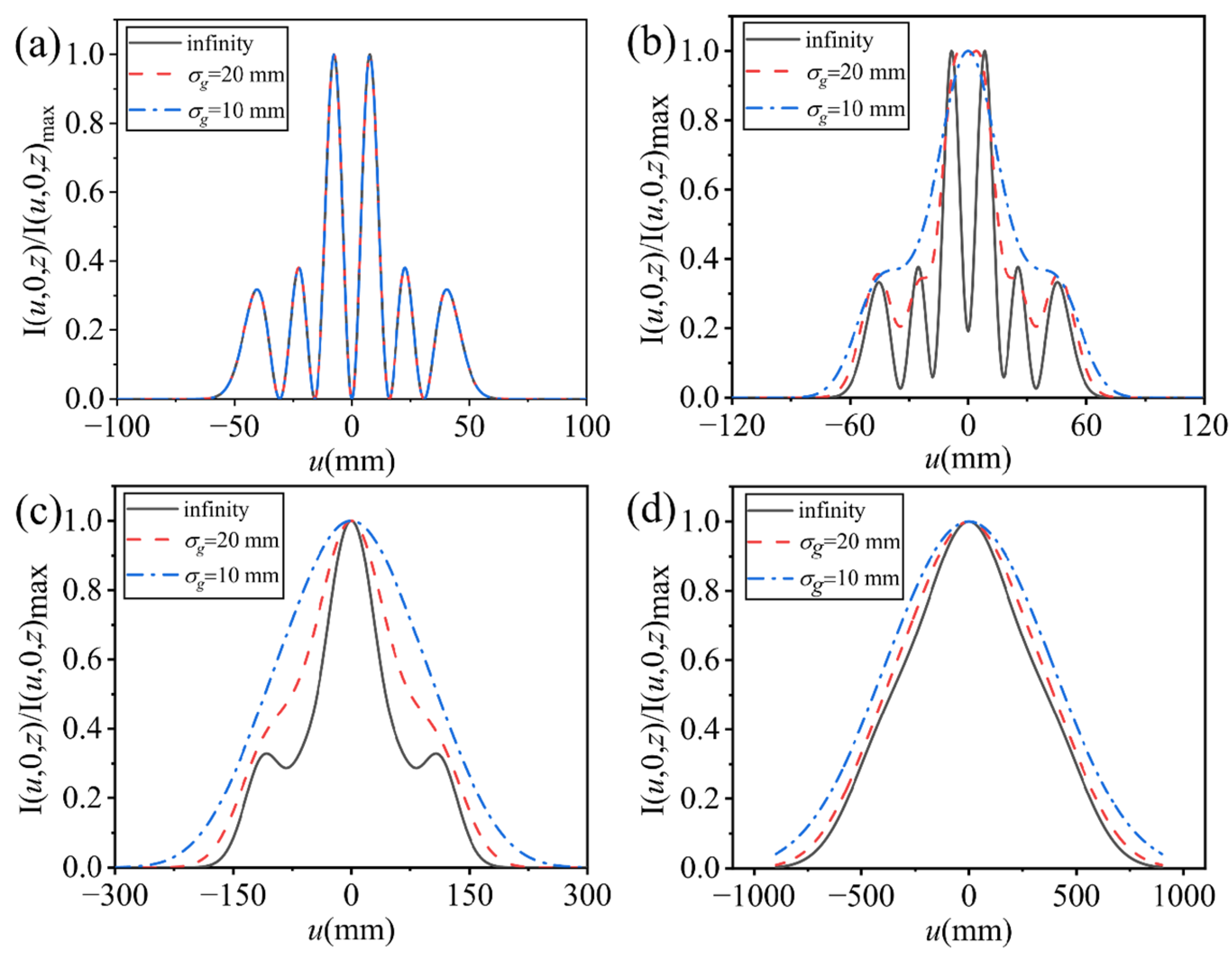
Figure 1. Cross-sectional lines (v = 0) of the normalized intensity of a PCLG beam with different initial transverse coherence widths at (a) z = 0 km, (b) z = 1 km, (c) z = 5 km, and (d) z = 20 km for forward transmission.
Photonics 11 01111 g001
Figure 2. Cross-sectional lines (v = 0) of the normalized intensity of a PCLG beam with different initial transverse coherence widths at (a) z = 0 km, (b) z = 0.5 km, (c) z = 5 km, and (d) z = 15 km for reverse transmission.
Photonics 11 01111 g002
Figure 3. Cross-sectional lines (v = 0) of the normalized average intensity of a PCLG beam with different beam orders at (a,b) z = 0 km, (c,d) z = 1.5 km, (e,f) z = 5 km when p = 1 for forward (a,c,e) and reverse (b,d,f) transmission.
Photonics 11 01111 g003
Figure 4. Cross-sectional lines (v = 0) of the normalized average intensity of a PCLG beam with different wavelengths at (a,b) z = 0 km, (c,d) z = 0.5 km, and (e,f) z = 5 km when p = 1 and l = 2 for forward (a,c,e) and reverse (b,d,f) transmission.
Photonics 11 01111 g004
Figure 5. Effective beam width of a PCLG beam with different beam orders, transverse coherence widths, and wavelengths for the forward (a,c,e) and reverse (b,d,f) transverse when ω0 = 40 mm, σg = 10 mm, p = 1, and l = 1.
Photonics 11 01111 g005
Figure 6. Normalized M2 factor of a PCLG beam with different structural constants of the atmospheric turbulence and beam orders when w0 = 40 mm for forward (a,c) and reverse (b,d) transmission.
Photonics 11 01111 g006
Figure 7. Normalized M2 factor of a PCLG beam with different structural constants of the atmospheric turbulence and transverse coherence widths when p = 3, l = 2, and w0 = 40 mm for forward (a) and reverse (b) transmission.
Photonics 11 01111 g007
Figure 8. Normalized M2 factor of a PCLG beam with different structural constants of the atmospheric turbulence and wavelengths when p = 3, l = 2, and w0 = 40 mm for forward (a) and reverse (b) transmission.
Photonics 11 01111 g008
Disclaimer/Publisher’s Note: The statements, opinions and data contained in all publications are solely those of the individual author(s) and contributor(s) and not of MDPI and/or the editor(s). MDPI and/or the editor(s) disclaim responsibility for any injury to people or property resulting from any ideas, methods, instructions or products referred to in the content.