Article

Chromatic Aberration in Wavefront Coding Imaging with Trefoil Phase Mask

1
Facultad de Física, Universidad de Santiago de Compostela, 15782 Santiago de Compostela, Spain
2
Facultad de Óptica y Optometría, Universidad de Santiago de Compostela, 15782 Santiago de Compostela, Spain
3
iMATUS (Materials Institute), Universidad de Santiago de Compostela, 15782 Santiago de Compostela, Spain
*
Author to whom correspondence should be addressed.
Photonics 2024, 11(12), 1117; https://doi.org/10.3390/photonics11121117
Submission received: 13 October 2024 / Revised: 22 November 2024 / Accepted: 25 November 2024 / Published: 26 November 2024
(This article belongs to the Special Issue Adaptive Optics Imaging: Science and Applications)

Abstract

:
The refractive index of the lenses used in optical designs varies with wavelength, causing light rays to fail when focusing on a single plane. This phenomenon is known as chromatic aberration (CA), chromatic distortion, or color fringing, among other terms. Images affected by CA display colored halos and experience a loss of resolution. Fully achromatic systems can be achieved through complex and costly lens designs and/or computationally when digital sensors capture the image. In this work, we propose using the wavefront coding (WFC) technique with a trefoil-shaped phase modulation plate in the optical system to effectively increase the resolution of images affected by longitudinal chromatic aberration (LCA), significantly simplifying the optical design and reducing costs. Experimental results with three LEDs simulating RGB images verify that WFC with trefoil phase plates effectively corrects longitudinal chromatic aberration. Transverse chromatic aberration (TCA) is corrected computationally. Furthermore, we demonstrate that the optical system maintains depth of focus (DoF) for color images.

1. Introduction

Chromatic aberration occurs in imaging systems due to the dependence of the refractive index of lenses on wavelength. As a result, different wavelengths focus on different distances along the optical axis, a phenomenon known as longitudinal chromatic aberration (LCA), or exhibit varying magnifications, known as transverse chromatic aberration (TCA) [1]. Both aberrations produce blurred, colored images and degrade image quality. Traditional achromatic or apochromatic corrections typically involve combining positive and negative lenses with different refractive indices or using hybrid refractive–diffractive optics to correct for a finite set of wavelengths, depending on the application. TCA can be corrected in optical systems with digital sensors by appropriately shifting or scaling the RGB channels [2]. Optical solutions generally correct for two or three specific wavelengths, leaving other wavelengths in the spectrum uncorrected. Therefore, for optical systems operating across a wide spectral range, chromatic aberrations are a critical issue that must be corrected or minimized to optimize imaging performance and achieve the desired resolution. Such corrections are not only expensive but can also introduce manufacturing challenges in lens production.
Wavefront coding (WFC) is a hybrid optical–computational imaging technique proposed by Dowski and Cathey to extend the depth of field (DoF) in incoherent imaging systems [3]. WFC modifies the optical path by introducing a specially designed phase mask (PM), typically placed at the exit pupil of the optical system, or shaping the surfaces of one lens of the optical system [4,5]. This phase mask introduces a controlled amount of aberration, making the system’s point spread function (PSF) invariant to defocus. The recorded (or intermediate) image is then restored through deconvolution using the corresponding optical transfer function (OTF), which must be free of nulls, resulting in a sharp image without the need for mechanical refocusing. Applications include thermal imaging [4], reduction in laser damage [5], deflectometry [6] and microscopy [7], among others.
Since longitudinal chromatic aberration (LCA) causes the image position to shift with wavelength, the extended DoF provided by WFC is a promising method for minimizing its effects. The use of this simple, low-cost, lightweight optical element for chromatic compensation significantly reduces the complexity of optical systems [4], making it an attractive option for minimizing chromatic aberration.
The effectiveness of this technique has already been demonstrated using a cubic PM [8,9] of the form α ( x 3 + y 3 ) , where α represents the strength of the mask, yielding the peak-to-valley value of the cubic phase that encodes the optical system. However, due to the symmetry of the cubic mask, artifacts in the shape of parallel fringes tend to appear in systems with circular pupils. This paper explores the performance of a trefoil-shaped PM for color imaging.

2. Methodology

2.1. Theoretical Bakcground

As shown in Figure 1, a WFC-based optical system comprises a PM that encodes an amount of aberration, W x , y , such that the PSF of the system, h ( x , y , z ) , is invariant to misfocus, ∆z.
h x , y , z P e x p j k W x P , y P + z f 2 x P 2 + y P 2 e x p j k f x x P + y y P d x P d y P
where x , y are the pupil coordinates, j is the imaginary unit, k is the wave number, f the focal distance, and P denotes the exit pupil. For incoherent illumination, the intermediate image is given by
i w f c x , y , z = o x , y h ( x , y , z ) 2
o x , y being the intensity of the object and i w f c x , y , z the intensity of the intermediate image. Due to the invariance of the PSF, o x , y can be restored through deconvolution using h ( x , y , 0 ) 2 . To avoid ill-conditioning, the PM must also ensure that the OTF at focus given by F h ( x , y , 0 ) 2 has no nulls, F denoting the Fourier transform. Different filters or methods can be used to deconvolve the intermediate images [10,11,12,13,14] and the strength of the PM can be jointly optimized [15]. The choice should be based on the specific requirements of the application. In this work, we will use the Wiener filter [11] in the frequency domain to restore the image due to its simplicity:
O r = I w f c · O T F z = 0 * O T F z = 0 2 + K
O r is the spectrum of the restored image, I w f c is the spectrum of the intermediate image, O T F z = 0 is the optical transfer function at focus, and K is the noise regularization parameter manually selected for best visual results. K is a matrix with the same dimensions as the OTF, with all elements set to 6 × 10 6 for all the processed intermediate images, since each has an SNR of approximately 14. This SNR is defined as the ratio of the mean intensity value over the upper white square of the USAF target subtracting the background intensity from a dark area to the standard deviation of the noise.
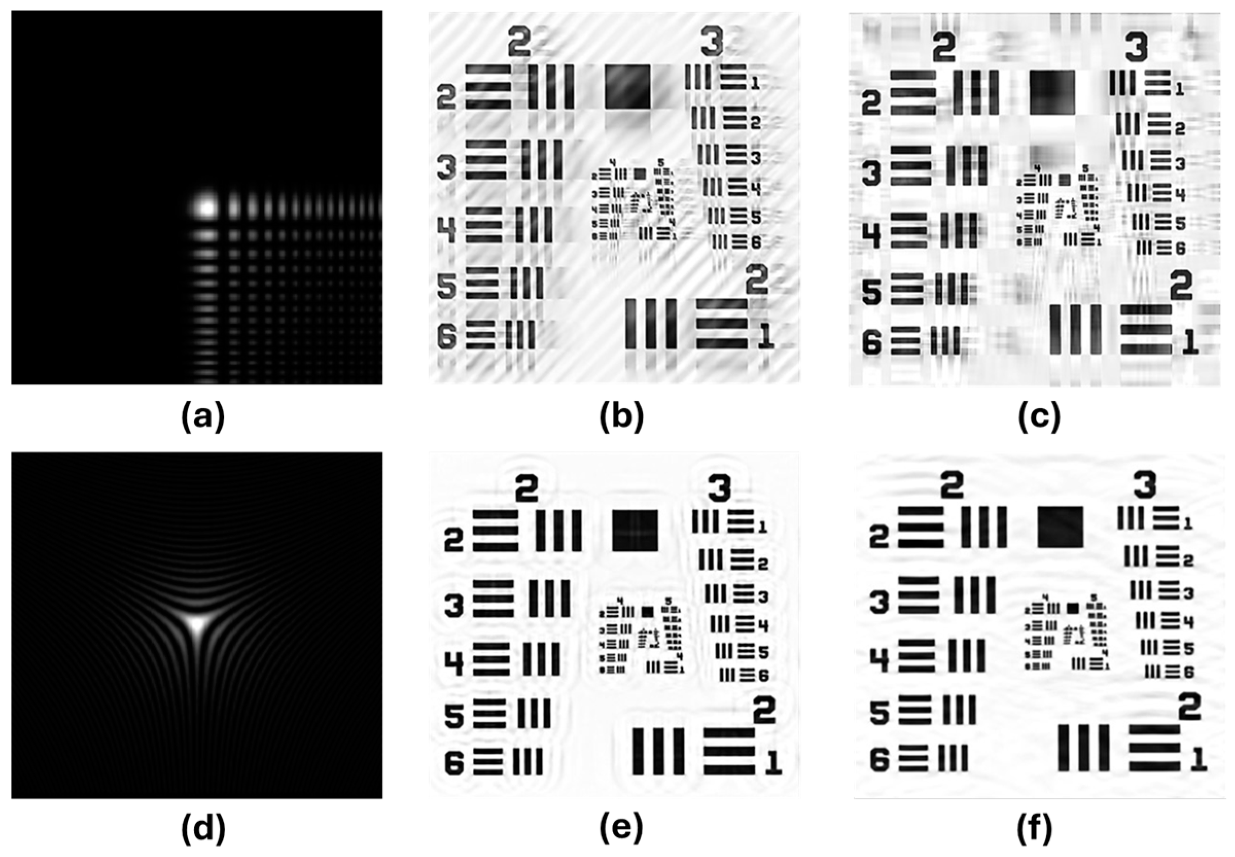
The choice of PMs to enhance the quality of digitally restored images is a critical aspect of wavefront coding. Since the original cubic PM proposed by Dowski et al. [3], many other PMs have been explored to improve its performance [16,17]. All these PMs share a common feature: their shape can be described by the separation of the X and Y variables in Cartesian coordinates, resulting in a PSF like that of the cubic PM, as shown in Figure 2a. For circular pupils, deconvolution with the OTF introduces artifacts in the restored defocused images [18,19,20]. These artifacts appear as parallel fringes or bands (Figure 2b), the orientation of which depends on the PM’s orientation. However, such artifacts are absent for square pupils (Figure 2c).
To minimize the banding patterns caused by a cubic PM and circular pupils, Prasad et al. [21] demonstrated that using a symmetric mixed cubic or trefoil phase, in the form ( x 3 + 3 x y 2 ) (or rotated), effectively reduces fringe artifacts in restored images. Figure 2d shows the PSF for a circular pupil, along with restored images for both circular (Figure 2e) and square (Figure 2f) pupils. These artifacts should not be confused with the replicas observed around the edges of the object (Figure 2b,c,e,f), which result from a mismatch between the convolution PSF and the deconvolution PSF [19]. Such artifacts can be minimized by using more advanced deconvolution filters or by shaping the PM as a higher-order polynomial [20]. The contrast and spacing of these artifacts depend on factors such as the strength of the PM, the f-number, and the amount of defocus.
Moreover, two consecutive, identical trefoil PMs allow for a continuously variable amount of trefoil ranging from zero to twice the strength of a single mask, depending on the relative angle between the PMs. This flexibility enables the extension of the DoF based on the requirements of the optical system [22,23].
Given the importance of circular pupils in optical systems, this work demonstrates the effectiveness of trefoil phase masks in compensating LCA avoiding band artifacts.

2.2. Experimental Setup

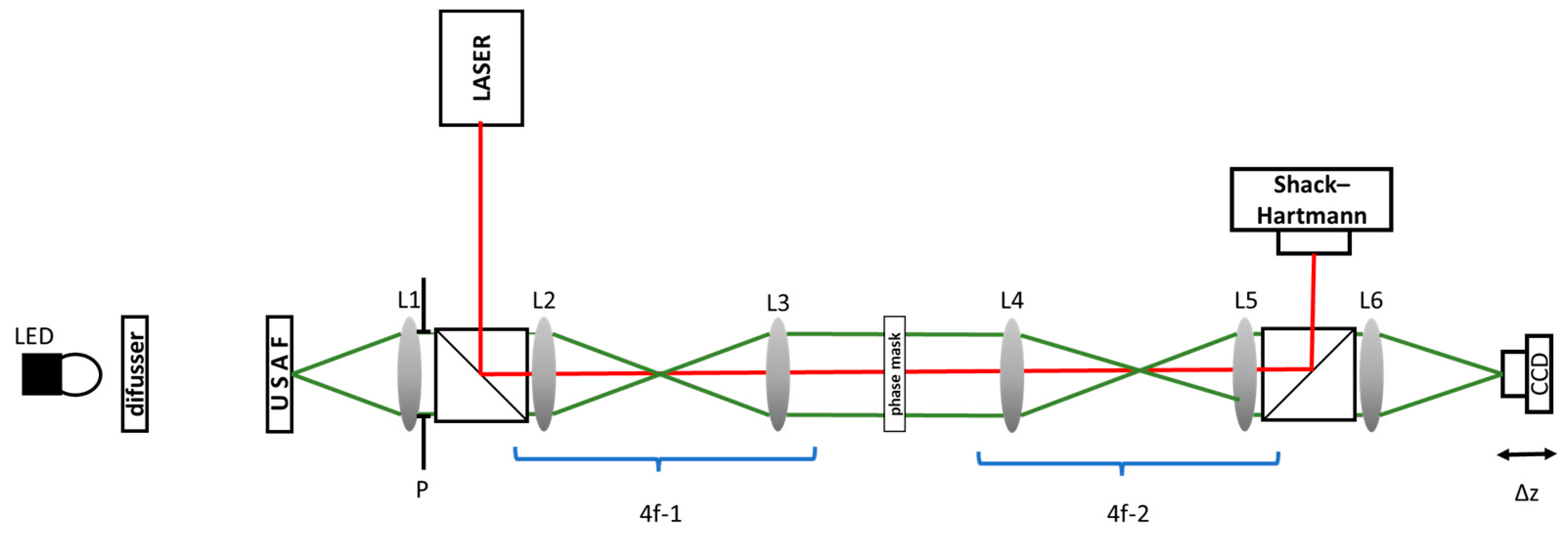
The experimental setup is shown schematically in Figure 3. All lenses used in the setup were singlets. Two 4f arrangements were included to evaluate the amount of trefoil generated by the PM as well as other aberrations using a Shack–Hartmann wavefront sensor (Thorlabs WFS31-7AR) (@633nm). The red line indicated the ray path. The laser beam was collimated by standard procedures. L1, L2, L3, L4 and L5 had a focal length of 50 mm, and L6 had a focal length of 100 mm. An aperture stop was placed in front of L1 and the PM was placed in between L2 and L3 in a plane conjugated with L1. For color imaging, we used three LEDs with central wavelengths of 660 nm for red, 565 nm for green, and 470 nm for blue. The LEDs illuminated a USAF target, used as the object, and a trefoil-shaped PM in the shape x 3 + 3 x y 2 at the system’s pupil (5 mm diameter). A CCD camera (Hamamatsu ORCA R2, Japan) captured 16-bit grayscale intermediate images at the green focus, z = 0 . Additional images were taken at z = 0.5 , + 0.5 , 1   mm to demonstrate that the LCA correction was also achievable at defocused planes. Separate images were captured for the three LEDs, and color images were simulated by merging these three images.
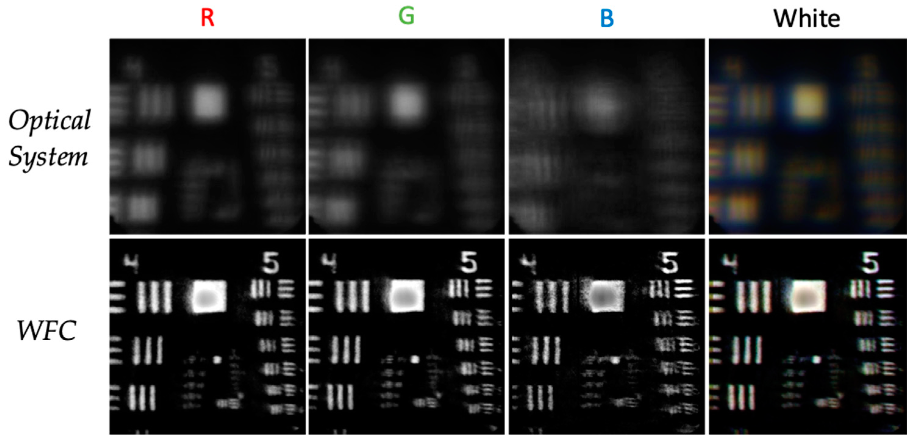
We also conducted the experiment using a white LED and a Thorlabs DCC1645C Color CMOS camera (Germany), with central wavelengths of 600 nm (R), 540 nm (G), and 460 nm (B) for the RGB filters.
In Figure 4, we present the PM fabricated using diamond turning in PMMA, along with the PSF at the red focus (a) and the measured aberrations using the wavefront sensor, trefoil aberration (b), and other aberrations (c) for different aperture radii. The PM was shaped as a trefoil but as can be seen from Figure 4c, the PM not only generates trefoil but also introduces small amounts of spherical aberration, astigmatism and coma. In ref. [24], we demonstrate through Zemax simulations that shaping the PM as a linear combination of trefoil and spherical aberrations significantly minimizes spherical aberration. However, since only the PM used in this study is available in our laboratory, the aberrations are not minimized, and the PM is not optimized to obtain the maximum or desired depth of field. Astigmatism and coma are practically negligible. Spherical aberration is small, but its primary effect would be a wavelength-dependent shift in focal position [25], which in our case slightly reduces the depth of focus for white light. Despite this, the main objective of this work—demonstrating longitudinal chromatic aberration (LCA) correction in WFC-based optical systems—remains achievable.
We capture the PSF image at the green focal plane and rotate the mask so that one of its symmetry axes aligns with either the vertical or horizontal axis of the CCD. With this orientation, we then construct the synthetic OTF for deconvolution. Deconvolution was made with a synthetic PSF computed by considering a 100 mm focal length lens (L6) with a 5 mm pupil. Based solely on the trefoil aberration value provided by the Shack–Hartmann sensor at 633 nm, we estimate the shape of the PM and thus the encoded phase is straightforwardly calculated for the three central wavelengths of the LEDs, accounting for the refractive index of PMMA.

3. Results

3.1. RGB LEDs

At the focal plane for the green channel, z = 0 , we recorded images with and without the PM. Figure 5 shows the results. The upper row shows the three images for the RGB LEDs of the traditional optical system. The middle row shows the intermediate images and the lower row the decoded images. It can be observed that for all three channels, the decoded images exhibit good resolution and contrast. However, for the traditional optical system, only the green channel provides good quality, while the blue and red channels appear blurred, as expected due to the chromatic aberration of the lenses. The last column merges the three channels to create the color composition. The decoded image is free from longitudinal chromatic aberration (LCA) but still shows transverse chromatic aberration (TCA). The color image highlights the blurring and color fringing caused by both types of CA.
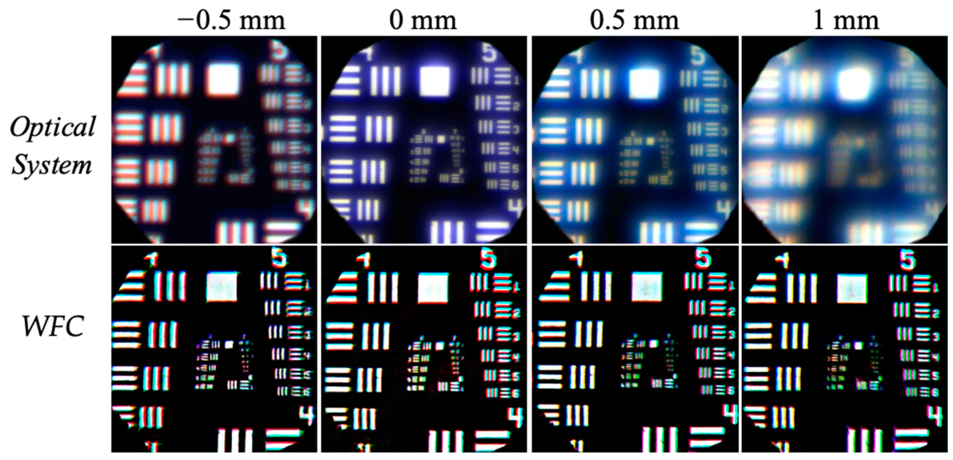
We captured images at four different defocused distances from the green focal plane, with z = 0.5 , 0 , + 0.5 , 1   mm . In Figure 6, we show the decoded color images in the upper row and the images affected by the chromatic aberration of the system in the lower row.
The WFC technique still extends the DoF for the three wavelengths. Outside the interval [−0.5, 1], decoded images lose sharpness and overall quality. Based on the algorithm to reduce lateral chromatic aberration proposed by Utsugi et al. [26], we processed the WFC image at z = 0   mm . In Figure 7, it can be observed that TCA has been noticeably reduced. It is important to note that the software we developed is neither automatic nor optimized as in Utsugi’s work; better results could be achieved, especially in the central region of the image. However, the aim of this work is to demonstrate that LCA can be corrected with WFC, not TCA.

3.2. White Light

In this section, for the sake of conciseness, we present only the results for the white LED at z = 1   mm . Due to the camera’s properties, the resolution is lower, but WFC is still able to significantly correct for LCA. TCA has been also corrected as previously explained. The results are shown in Figure 8.

4. Discussion

Most methods for achromatizing an optical system require different lens materials and can only correct for a limited set of wavelengths. In this work, we demonstrate that the wavefront coding technique comprising trefoil phase masks can effectively correct longitudinal chromatic aberration over a wide range of wavelengths.
A fully achromatic optical system can be achieved by correcting lateral chromatic aberration through wavefront coding, combined with appropriate digital post-processing to address transverse chromatic aberration. In general, the use of wavefront coding, which integrates image processing with simple optics in the design of imaging systems, can lead to cost reductions. The choice of the phase mask is a key factor in this design. Cubic phase masks introduce bands in the restored images when used with circular pupils. Trefoil masks do not exhibit this problem.

Author Contributions

Conceptualization, E.A. and M.O.-A.; methodology, M.O.-A.; software, M.O.-A.; validation, E.A., J.A. and M.O.-A.; writing—original draft preparation, E.A.; writing—review and editing, E.A.; funding acquisition, E.A. and J.A. All authors have read and agreed to the published version of the manuscript.

Funding

This research was funded by the Ministerio de Ciencia e Innovacion and European (FEDER) funds, grant number PID2020-115909RB-100.

Institutional Review Board Statement

Not applicable.

Informed Consent Statement

Not applicable.

Data Availability Statement

Data will be available on demand.

Conflicts of Interest

The authors declare no conflicts of interest.

References

  1. Kingslake, R.; Johnson, B.B. Lens Design Fundamentals, 2nd ed.; Academic Press: Burlington, VT, USA, 2010; pp. 137–163. [Google Scholar]
  2. Korneliussen, J.T.; Hirakawa, K. Camera processing with chromatic aberration. IEEE Trans. Image Process. 2014, 23, 4539–4552. [Google Scholar] [CrossRef] [PubMed]
  3. Dowski, E.R.; Cathey, W.T. Extended depth of field through wave-front coding. Appl. Opt. 1995, 34, 1859–1886. [Google Scholar] [CrossRef] [PubMed]
  4. Kubala, k.; Dowski, E.R.; Cathey, W.T. Reducing complexity in computational imaging systems. Opt. Express 2003, 11, 2102–2108. [Google Scholar] [CrossRef] [PubMed]
  5. Ye, Q.; Wu, Y.M.; Zhang, H.; Li, Y.; Wang, L.; Sun, K. Experimental damage thresholds of a laser suppression imaging system using a cubic phase plate. Chin. Opt. Lett. 2023, 21, 041403. [Google Scholar] [CrossRef]
  6. Niu, Z.; Wang, J.; Tian, Y.; Wu, Z.; Wei, C.; Shao, J. Wavefront-coded phase measuring deflectometry for the all-focused measurement. Opt. Lett. 2022, 47, 4770–4773. [Google Scholar] [CrossRef] [PubMed]
  7. Arnison, M.R.; Cogswell, C.J.; Sheppard, C.J.R.; Török, P. Wavefront Coding Fluorescence Microscopy Using High Aperture Lenses. In Optical Imaging and Microscopy; Springer Series in Optical Sciences; Springer: Berlin/Heidelberg, Germany, 2003; Volume 87. [Google Scholar] [CrossRef]
  8. Fontbonne, A.; Trouvé-Peloux, P.; Tartas, E.; Druart, G. Depth of Focus Extension Wavefront Coding Methods for Fast Imaging Systems. In Optica Design and Fabrication Congress 2023 (IODC, OFT); Technical Digest Series; Optica Publishing Group: Washington, DC, USA, 2023; p. 127981M. [Google Scholar] [CrossRef]
  9. Wach, H.B.; Dowski, E.R.; Cathey, W.T. Control of chromatic focal shift through wave-front coding. Appl. Opt. 1998, 37, 5359–5367. [Google Scholar] [CrossRef] [PubMed]
  10. Akpinar, U.; Sahin, E.; Meem, M.; Menon, R.; Gotchev, A. Learning Wavefront Coding for Extended Depth of Field Imaging. IEEE Trans. Image Process. 2021, 30, 3307–3320. [Google Scholar] [CrossRef] [PubMed]
  11. Gonzalez, R.C.; Woods, R.E. Digital Image Processing, 4th ed.; Pearson: New York, NY, USA, 2018; pp. 317–368. [Google Scholar]
  12. Wei, S.; Cheng, H.; Xue, B.; Shao, X.; Xi, L. Low-cost and simple optical system based on wavefront coding and deep learning. Appl. Opt. 2023, 62, 6171–6179. [Google Scholar] [CrossRef] [PubMed]
  13. Fontbonne, A.; Sauer, H.; Goudail, F. Comparison of methods for end-to-end co-optimization of optical systems and image processing with commercial lens design software. Opt. Express 2022, 30, 13556–13571. [Google Scholar] [CrossRef] [PubMed]
  14. Diaz, F.; Goudail, F.; Loiseaux, B.; Huignard, J.-P. Increase in depth of field taking into account deconvolution by optimization of pupil mask. Opt. Lett. 2009, 34, 2970–2972. [Google Scholar] [CrossRef] [PubMed]
  15. Zhang, Q.; Bao, M.; Sun, L.; Liu, Y.; Zheng, J. Wavefront coding image reconstruction via physical prior and frequency attention. Opt. Express 2023, 31, 32875–32886. [Google Scholar] [CrossRef] [PubMed]
  16. Zhao, H.; Li, Y. Optimized logarithmic phase masks used to generate defocus invariant modulation transfer function for wavefront coding system. Opt. Lett. 2010, 35, 2630–2632. [Google Scholar] [CrossRef] [PubMed]
  17. Le, V.N.; Chen, S.; Fan, Z. Optimized asymmetrical tangent phase mask to obtain defocus invariant modulation transfer function in incoherent imaging systems. Opt. Lett. 2014, 39, 2171–2174. [Google Scholar] [CrossRef] [PubMed]
  18. Scrymgeour, D.A.; Adelsberger, K.; Boye, R. Advanced Imaging Optics Utilizing Wavefront Coding; Sandia Report SAND2015-4431; Office of Scientific and Technical Information: Oak Ridge, TN, USA, 2015. [CrossRef]
  19. Demenikov, M.; Harvey, A.R. Image artifacts in hybrid imaging systems with a cubic phase mask. Opt. Express 2010, 18, 8207–8212. [Google Scholar] [CrossRef] [PubMed]
  20. Demenikov, M.; Harvey, A.R. A technique to remove image artefacts in optical systems with wavefront coding. In Novel Optical Systems Design and Optimization XII; SPIE: Bellingham, WA, USA, 2009; Volume 7429. [Google Scholar] [CrossRef]
  21. Prasad, S.; Torgersen, T.C.; Pauca, V.P.; Plemmons, R.J.; van der Gracht, J. Engineering the pupil phase to improve image quality. In Visual Information Processing XII; SPIE: Bellingham, WA, USA, 2003; Volume 5108. [Google Scholar] [CrossRef]
  22. Acosta, E. Adaptive phase plates for optical encoding systems invariant to second-order aberrations. Opt. Commun. 2011, 284, 3862–3866. [Google Scholar] [CrossRef]
  23. Demenikov, M.; Muyo, G.; Harvey, A.R. Experimental demonstration of continuously variable optical encoding in a hybrid imaging system. Opt. Lett. 2010, 35, 2100–2102. [Google Scholar] [CrossRef] [PubMed]
  24. Olvera-Angeles, M.; Padilla-Vivanco, A.; Ortega, K.; Sasian, J.; Schwiegerling, J.; Arines, J. Eva Acosta Optimizing trefoil phase plates design for color wavefront coding. In Current Developments in Lens Design and Optical Engineering XIX; SPIE: Bellingham, WA, USA, 2018; Volume 1074. [Google Scholar] [CrossRef]
  25. Shi, Y.; Chen, S.; Le, V.N.; Fan, Z.; Zhang, W. Performance analysis of wavefront coding system with spherical aberration by using ray aberration approach. Optik 2017, 130, 1266–1271. [Google Scholar] [CrossRef]
  26. Utsugi, A.; Ishiga, K. Correcting lateral chromatic aberrations by image processing. In International Optical Design Conference; SPIE: Bellingham, WA, USA, 2010; Volume 76520. [Google Scholar] [CrossRef]
Figure 1. WFC-based optical system.
Photonics 11 01117 g001
Figure 2. (a) Cubic PSF for circular pupil, (b) restored image for circular pupil and (c) restored image for square pupil. (d) Trefoil PSF for circular pupil, (e) restored image for circular pupil and (f) restored image for square pupil.
Photonics 11 01117 g002
Figure 3. Scheme of the experimental device.
Photonics 11 01117 g003
Figure 4. Properties of fabricated PM: (a) PM and center of PSF, (b) trefoil aberration and (c) other aberrations.
Photonics 11 01117 g004
Figure 5. RGB LED images and merged color images: optical system (upper row), intermediate images (middle row), and decoded images (lower row).
Photonics 11 01117 g005
Figure 6. Decoded color images with trefoil PM (lower row) and corresponding images with chromatic aberration for the optical system (upper row) for different defocused recording planes.
Photonics 11 01117 g006
Figure 7. Color image of decoded image with trefoil PM (a), and corresponding image with TCA reduced by image processing (b).
Photonics 11 01117 g007
Figure 8. RGB for white LED images and merged color images: optical system (upper row) and decoded images (lower row).
Photonics 11 01117 g008
Disclaimer/Publisher’s Note: The statements, opinions and data contained in all publications are solely those of the individual author(s) and contributor(s) and not of MDPI and/or the editor(s). MDPI and/or the editor(s) disclaim responsibility for any injury to people or property resulting from any ideas, methods, instructions or products referred to in the content.