Applications of Microstructured Optical Fibers in Ultrafast Optics: A Review


Abstract
:1. Introduction
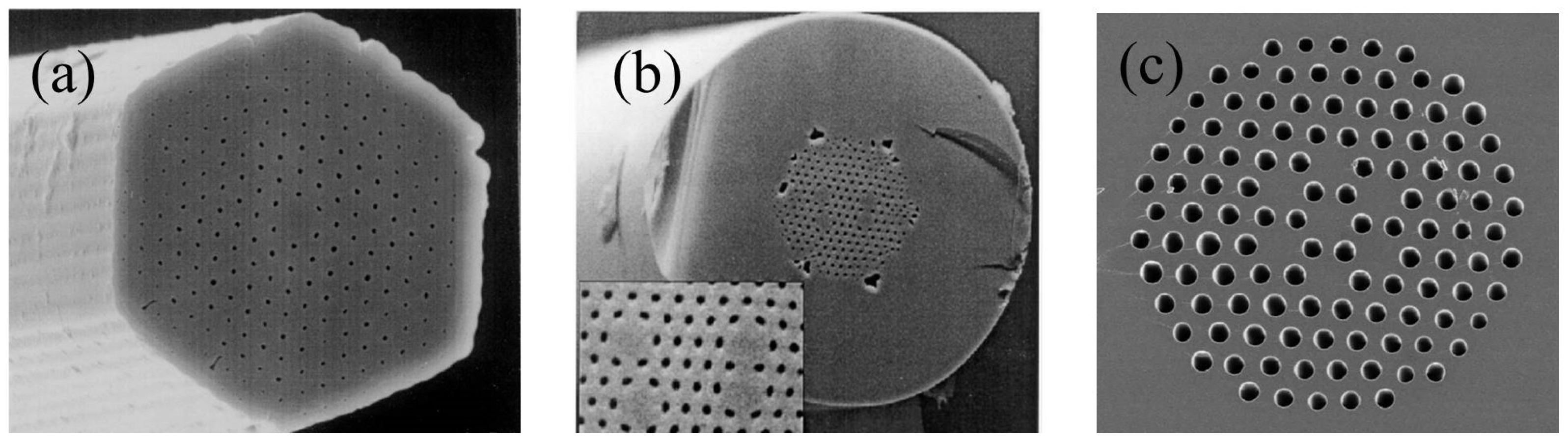
2. Types of MOFs
2.1. Total Internal Reflection MOFs
2.2. Photonic Bandgap Fiber
2.3. Hollow-Core Anti-Resonant Fiber
2.4. Hybrid Light Guiding MOFs
3. Applications of MOFs in Ultrafast Optics
3.1. Pulse Amplification
3.2. Spectrum Engineering
3.2.1. Supercontinuum Generation

3.2.2. UV Generation
3.2.3. IR Generation
3.3. Pulse Compression
3.4. High-Harmonic Mode-Locking Soliton Lasers
3.5. Coherent Anti-Stokes Raman Scattering
4. Conclusions and Outlook
Author Contributions
Funding
Institutional Review Board Statement
Informed Consent Statement
Data Availability Statement
Conflicts of Interest
References
- Siek, F.; Neb, S.; Bartz, P.; Hensen, M.; Strüber, C.; Fiechter, S.; Torrent-Sucarrat, M.; Silkin, V.M.; Krasovskii, E.E.; Kabachnik, N.M. Angular momentum–induced delays in solid-state photoemission enhanced by intra-atomic interactions. Science 2017, 357, 1274–1277. [Google Scholar] [CrossRef]
- Géneaux, R.; Kaplan, C.J.; Yue, L.; Ross, A.D.; Bækhøj, J.E.; Kraus, P.M.; Chang, H.-T.; Guggenmos, A.; Huang, M.-Y.; Zürch, M. Attosecond time-domain measurement of core-level-exciton decay in magnesium oxide. Phys. Rev. Lett. 2020, 124, 207401. [Google Scholar] [CrossRef]
- Calegari, F.; Ayuso, D.; Trabattoni, A.; Belshaw, L.; De Camillis, S.; Anumula, S.; Frassetto, F.; Poletto, L.; Palacios, A.; Decleva, P. Ultrafast electron dynamics in phenylalanine initiated by attosecond pulses. Science 2014, 346, 336–339. [Google Scholar] [CrossRef] [PubMed]
- Mara, M.W.; Hadt, R.G.; Reinhard, M.E.; Kroll, T.; Lim, H.; Hartsock, R.W.; Alonso-Mori, R.; Chollet, M.; Glownia, J.M.; Nelson, S. Metalloprotein entatic control of ligand-metal bonds quantified by ultrafast X-ray spectroscopy. Science 2017, 356, 1276–1280. [Google Scholar] [CrossRef] [PubMed]
- Sansone, G.; Kelkensberg, F.; Pérez-Torres, J.; Morales, F.; Kling, M.F.; Siu, W.; Ghafur, O.; Johnsson, P.; Swoboda, M.; Benedetti, E. Electron localization following attosecond molecular photoionization. Nature 2010, 465, 763–766. [Google Scholar] [CrossRef] [PubMed]
- Scherer, N.; Knee, J.; Smith, D.; Zewail, A. Femtosecond photofragment spectroscopy: The reaction ICN→CN + I. J. Phys. Chem. 1985, 89, 5141–5143. [Google Scholar] [CrossRef]
- McClung, F.J.; Hellwarth, R.W. Giant optical pulsations from ruby. Appl. Opt. 1962, 1, 103–105. [Google Scholar] [CrossRef]
- Fork, R.; Greene, B.; Shank, C.V. Generation of optical pulses shorter than 0.1 psec by colliding pulse mode locking. Appl. Phys. Lett. 1981, 38, 671–672. [Google Scholar] [CrossRef]
- Hentschel, M.; Kienberger, R.; Spielmann, C.; Reider, G.A.; Milosevic, N.; Brabec, T.; Corkum, P.; Heinzmann, U.; Drescher, M.; Krausz, F. Attosecond metrology. Nature 2001, 414, 509–513. [Google Scholar] [CrossRef]
- Strycker, B.D.; Han, Z.; Commer, B.; Shaw, B.D.; Sokolov, A.V.; Scully, M.O. CARS spectroscopy of Aspergillus nidulans spores. Sci. Rep. 2019, 9, 1789. [Google Scholar] [CrossRef]
- Lee, J.H.; Cho, E.H.; Shin, S.-M.; Oh, M.-K.; Ko, D.-K. Comparative study of breast normal and cancer cells using coherent anti-Stokes Raman scattering microspectroscopy imaging. Appl. Phys. Express 2012, 5, 082401. [Google Scholar] [CrossRef]
- Kurokawa, K.; Tajima, K.; Nakajima, K. 10-GHz 0.5-ps pulse generation in 1000-nm band in PCF for high-speed optical communication. J. Light. Technol. 2007, 25, 75–78. [Google Scholar] [CrossRef]
- Schibli, T.; Hartl, I.; Yost, D.; Martin, M.; Marcinkevičius, A.; Fermann, M.; Ye, J. Optical frequency comb with submillihertz linewidth and more than 10 W average power. Nat. Photonics 2008, 2, 355–359. [Google Scholar] [CrossRef]
- Zhu, W.; Yi, Y.; Yi, Z.; Bian, L.; Yang, H.; Zhang, J.; Yu, Y.; Liu, C.; Li, G.; Wu, X. High confidence plasmonic sensor based on photonic crystal fibers with a U-shaped detection channel. Phys. Chem. Chem. Phys. 2023, 25, 8583–8591. [Google Scholar] [CrossRef]
- Wang, D.; Zhu, W.; Yi, Z.; Ma, G.; Gao, X.; Dai, B.; Yu, Y.; Zhou, G.; Wu, P.; Liu, C. Highly sensitive sensing of a magnetic field and temperature based on two open ring channels SPR-PCF. Opt. Express 2022, 30, 39055–39067. [Google Scholar] [CrossRef] [PubMed]
- Jing, J.; Liu, K.; Jiang, J.; Xu, T.; Wang, S.; Liu, T. Highly sensitive and stable probe refractometer based on configurable plasmonic resonance with nano-modified fiber core. Opto-Electron. Adv. 2023, 6, 220072-1–220072-14. [Google Scholar] [CrossRef]
- Yang, L.; Li, Y.; Fang, F.; Li, L.; Yan, Z.; Zhang, L.; Sun, Q. Highly sensitive and miniature microfiber-based ultrasound sensor for photoacoustic tomography. Opto-Electron. Adv. 2022, 5, 200076-1–200076-8. [Google Scholar] [CrossRef]
- Russell, P.S.J. Photonic band gaps. Phys. World 1992, 5, 37. [Google Scholar] [CrossRef]
- Knight, J.; Birks, T.; Russell, P.S.J.; Atkin, D. All-silica single-mode optical fiber with photonic crystal cladding. Opt. Lett. 1996, 21, 1547–1549. [Google Scholar] [CrossRef]
- Mangan, B.; Knight, J.; Birks, T.; Russell, P.S.J.; Greenaway, A. Experimental study of dual-core photonic crystal fibre. Electron. Lett. 2000, 36, 1. [Google Scholar] [CrossRef]
- Xiang, H.; Jiang, Y. Fiber Bragg grating inscription in multi-core photonic crystal fiber by femtosecond laser. Optik 2018, 171, 9–14. [Google Scholar] [CrossRef]
- Birks, T.A.; Knight, J.C.; Russell, P.S.J. Endlessly single-mode photonic crystal fiber. Opt. Lett. 1997, 22, 961–963. [Google Scholar] [CrossRef]
- Knight, J.C.; Broeng, J.; Birks, T.A.; Russell, P.S.J. Photonic band gap guidance in optical fibers. Science 1998, 282, 1476–1478. [Google Scholar] [CrossRef]
- Chen, X.; Huang, L.; Yang, H.; Xi, X.; An, Y.; Yan, Z.; Chen, Y.; Pan, Z.; Zhou, P. Large-mode-area multi-resonant all-solid photonic bandgap fiber with low bending loss and robust single-mode operation. Opt. Laser Technol. 2023, 157, 108668. [Google Scholar] [CrossRef]
- Cregan, R.; Mangan, B.; Knight, J.; Birks, T.; Russell, P.S.J.; Roberts, P.; Allan, D. Single-mode photonic band gap guidance of light in air. Science 1999, 285, 1537–1539. [Google Scholar] [CrossRef]
- Benabid, F.; Knight, J.C.; Antonopoulos, G.; Russell, P.S.J. Stimulated Raman scattering in hydrogen-filled hollow-core photonic crystal fiber. Science 2002, 298, 399–402. [Google Scholar] [CrossRef]
- Smith, C.M.; Venkataraman, N.; Gallagher, M.T.; Müller, D.; West, J.A.; Borrelli, N.F.; Allan, D.C.; Koch, K.W. Low-loss hollow-core silica/air photonic bandgap fibre. Nature 2003, 424, 657–659. [Google Scholar] [CrossRef] [PubMed]
- Pryamikov, A.D.; Biriukov, A.S.; Kosolapov, A.F.; Plotnichenko, V.G.; Semjonov, S.L.; Dianov, E.M. Demonstration of a waveguide regime for a silica hollow-core microstructured optical fiber with a negative curvature of the core boundary in the spectral region >3.5 μm. Opt. Express 2011, 19, 1441–1448. [Google Scholar] [CrossRef] [PubMed]
- Gao, S.-F.; Wang, Y.-Y.; Ding, W.; Jiang, D.-L.; Gu, S.; Zhang, X.; Wang, P. Hollow-core conjoined-tube negative-curvature fibre with ultralow loss. Nat. Commun. 2018, 9, 2828. [Google Scholar] [CrossRef] [PubMed]
- Sakr, H.; Chen, Y.; Jasion, G.T.; Bradley, T.D.; Hayes, J.R.; Mulvad, H.C.H.; Davidson, I.A.; Numkam Fokoua, E.; Poletti, F. Hollow core optical fibres with comparable attenuation to silica fibres between 600 and 1100 nm. Nat. Commun. 2020, 11, 6030. [Google Scholar] [CrossRef] [PubMed]
- Duguay, M.; Kokubun, Y.; Koch, T.; Pfeiffer, L. Antiresonant reflecting optical waveguides in SiO2-Si multilayer structures. Appl. Phys. Lett. 1986, 49, 13–15. [Google Scholar] [CrossRef]
- Litchinitser, N.; Abeeluck, A.; Headley, C.; Eggleton, B. Antiresonant reflecting photonic crystal optical waveguides. Opt. Lett. 2002, 27, 1592–1594. [Google Scholar] [CrossRef] [PubMed]
- Cerqueira, S.A.; Luan, F.; Cordeiro, C.; George, A.; Knight, J. Hybrid photonic crystal fiber. Opt. Express 2006, 14, 926–931. [Google Scholar] [CrossRef]
- Paschotta, R.; Nilsson, J.; Tropper, A.C.; Hanna, D.C. Ytterbium-doped fiber amplifiers. IEEE J. Quantum Electron. 1997, 33, 1049–1056. [Google Scholar] [CrossRef]
- Limpert, J.; Clausnitzer, T.; Liem, A.; Schreiber, T.; Fuchs, H.-J.; Zellmer, H.; Kley, E.-B.; Tnnermann, A. High-average-power femtosecond fiber chirped-pulse amplification system. Opt. Lett. 2003, 28, 1984–1986. [Google Scholar] [CrossRef] [PubMed]
- Limpert, J.; Deguil-Robin, N.; Manek-Hönninger, I.; Salin, F.; Röser, F.; Liem, A.; Schreiber, T.; Nolte, S.; Zellmer, H.; Tünnermann, A. High-power rod-type photonic crystal fiber laser. Opt. Express 2005, 13, 1055–1058. [Google Scholar] [CrossRef] [PubMed]
- Röser, F.; Eidam, T.; Rothhardt, J.; Schmidt, O.; Schimpf, D.; Limpert, J.; Tünnermann, A. Millijoule pulse energy high repetition rate femtosecond fiber chirped-pulse amplification system. Opt. Lett. 2007, 32, 3495–3497. [Google Scholar] [CrossRef] [PubMed]
- Eidam, T.; Hanf, S.; Seise, E.; Andersen, T.V.; Gabler, T.; Wirth, C.; Schreiber, T.; Limpert, J.; Tünnermann, A. Femtosecond fiber CPA system emitting 830 W average output power. Opt. Lett. 2010, 35, 94–96. [Google Scholar] [CrossRef]
- Wan, P.; Yang, L.-M.; Liu, J. All fiber-based Yb-doped high energy, high power femtosecond fiber lasers. Opt. Express 2013, 21, 29854–29859. [Google Scholar] [CrossRef] [PubMed]
- Müller, M.; Kienel, M.; Klenke, A.; Gottschall, T.; Shestaev, E.; Plötner, M.; Limpert, J.; Tünnermann, A. 1 kW 1 mJ eight-channel ultrafast fiber laser. Opt. Lett. 2016, 41, 3439–3442. [Google Scholar] [CrossRef]
- Stark, H.; Buldt, J.; Müller, M.; Klenke, A.; Limpert, J. 1 kW, 10 mJ, 120 fs coherently combined fiber CPA laser system. Opt. Lett. 2021, 46, 969–972. [Google Scholar] [CrossRef]
- Stark, H.; Benner, M.; Buldt, J.; Klenke, A.; Limpert, J. Pulses of 32 mJ and 158 fs at 20-kHz repetition rate from a spatiotemporally combined fiber laser system. Opt. Lett. 2023, 48, 3007–3010. [Google Scholar] [CrossRef]
- Müller, M.; Aleshire, C.; Klenke, A.; Haddad, E.; Légaré, F.; Tünnermann, A.; Limpert, J. 10.4 kW coherently combined ultrafast fiber laser. Opt. Lett. 2020, 45, 3083–3086. [Google Scholar] [CrossRef]
- Limpert, J.; Stutzki, F.; Jansen, F.; Otto, H.-J.; Eidam, T.; Jauregui, C.; Tünnermann, A. Yb-doped large-pitch fibres: Effective single-mode operation based on higher-order mode delocalisation. Light Sci. Appl. 2012, 1, e8. [Google Scholar] [CrossRef]
- Alfano, R.; Shapiro, S. Emission in the region 4000 to 7000 Å via four-photon coupling in glass. Phys. Rev. Lett. 1970, 24, 584. [Google Scholar] [CrossRef]
- Knight, J.; Arriaga, J.; Birks, T.; Ortigosa-Blanch, A.; Wadsworth, W.; Russell, P.S.J. Anomalous dispersion in photonic crystal fiber. IEEE Photonics Technol. Lett. 2000, 12, 807–809. [Google Scholar] [CrossRef]
- Ranka, J.K.; Windeler, R.S.; Stentz, A.J. Visible continuum generation in air–silica microstructure optical fibers with anomalous dispersion at 800 nm. Opt. Lett. 2000, 25, 25–27. [Google Scholar] [CrossRef] [PubMed]
- Husakou, A.; Herrmann, J. Supercontinuum generation of higher-order solitons by fission in photonic crystal fibers. Phys. Rev. Lett. 2001, 87, 203901. [Google Scholar] [CrossRef] [PubMed]
- Husakou, A.V.; Herrmann, J. Supercontinuum generation, four-wave mixing, and fission of higher-order solitons in photonic-crystal fibers. JOSA B 2002, 19, 2171–2182. [Google Scholar] [CrossRef]
- Birks, T.; Wadsworth, W.; Russell, P.S.J. Supercontinuum generation in tapered fibers. Opt. Lett. 2000, 25, 1415–1417. [Google Scholar] [CrossRef] [PubMed]
- Genty, G.; Lehtonen, M.; Ludvigsen, H.; Broeng, J.; Kaivola, M. Spectral broadening of femtosecond pulses into continuum radiation in microstructured fibers. Opt. Express 2002, 10, 1083–1098. [Google Scholar] [CrossRef]
- Coen, S.; Chau, A.H.L.; Leonhardt, R.; Harvey, J.D.; Knight, J.C.; Wadsworth, W.J.; Russell, P.S.J. Supercontinuum generation by stimulated Raman scattering and parametric four-wave mixing in photonic crystal fibers. JOSA B 2002, 19, 753–764. [Google Scholar] [CrossRef]
- Sakamaki, K.; Nakao, M.; Naganuma, M.; Izutsu, M. Soliton induced supercontinuum generation in photonic crystal fiber. IEEE J. Sel. Top. Quantum Electron. 2004, 10, 876–884. [Google Scholar] [CrossRef]
- Genty, G.; Lehtonen, M.; Ludvigsen, H.; Kaivola, M. Enhanced bandwidth of supercontinuum generated in microstructured fibers. Opt. Express 2004, 12, 3471–3480. [Google Scholar] [CrossRef]
- Stone, J.M.; Knight, J.C. Visibly “white” light generation in uniform photonic crystal fiber using a microchip laser. Opt. Express 2008, 16, 2670–2675. [Google Scholar] [CrossRef]
- Chen, H.; Chen, Z.; Zhou, X.; Hou, J. Ultraviolet-extended flat supercontinuum generation in cascaded photonic crystal fiber tapers. Laser Phys. Lett. 2013, 10, 085401. [Google Scholar] [CrossRef]
- Stark, S.; Travers, J.; Russell, P.S.J. Extreme supercontinuum generation to the deep UV. Opt. Lett. 2012, 37, 770–772. [Google Scholar] [CrossRef]
- Qi, X.; Chen, S.; Li, Z.; Liu, T.; Ou, Y.; Wang, N.; Hou, J. High-power visible-enhanced all-fiber supercontinuum generation in a seven-core photonic crystal fiber pumped at 1016 nm. Opt. Lett. 2018, 43, 1019–1022. [Google Scholar] [CrossRef] [PubMed]
- Zhang, H.; Li, Y.; Yan, D.; Dong, K.; Lin, H.; Wang, J.; Jing, F. All-fiber high power supercontinuum generation by cascaded photonic crystal fibers ranging from 370 nm to 2400 nm. IEEE Photonics J. 2020, 12, 1–8. [Google Scholar] [CrossRef]
- Ermolov, A.; Mak, K.F.; Frosz, M.H.; Travers, J.C.; Russell, P.S.J. Supercontinuum generation in the vacuum ultraviolet through dispersive-wave and soliton-plasma interaction in a noble-gas-filled hollow-core photonic crystal fiber. Phys. Rev. A 2015, 92, 033821. [Google Scholar] [CrossRef]
- Delmonte, T.; Watson, M.A.; O’Driscoll, E.J.; Feng, X.; Monro, T.M.; Finazzi, V.; Petropoulos, P.; Price, J.H.; Baggett, J.C.; Loh, W. Generation of mid-IR continuum using tellurite microstructured fiber. In Proceedings of the 2006 Conference on Lasers and Electro-Optics and 2006 Quantum Electronics and Laser Science Conference, Long Beach, CA, USA, 21–26 May 2006; pp. 1–2. [Google Scholar]
- Domachuk, P.; Wolchover, N.; Cronin-Golomb, M.; Wang, A.; George, A.K.; Cordeiro, C.; Knight, J.C.; Omenetto, F. Over 4000 nm bandwidth of mid-IR supercontinuum generation in sub-centimeter segments of highly nonlinear tellurite PCFs. Opt. Express 2008, 16, 7161–7168. [Google Scholar] [CrossRef]
- Buczynski, R.; Bookey, H.; Klimczak, M.; Pysz, D.; Stepien, R.; Martynkien, T.; McCarthy, J.E.; Waddie, A.J.; Kar, A.K.; Taghizadeh, M.R. Two octaves supercontinuum generation in lead-bismuth glass based photonic crystal fiber. Materials 2014, 7, 4658–4668. [Google Scholar] [CrossRef]
- Liu, L.; Cheng, T.; Nagasaka, K.; Tong, H.; Qin, G.; Suzuki, T.; Ohishi, Y. Coherent mid-infrared supercontinuum generation in all-solid chalcogenide microstructured fibers with all-normal dispersion. Opt. Lett. 2016, 41, 392–395. [Google Scholar] [CrossRef] [PubMed]
- Wang, Y.; Dai, S.; Li, G.; Xu, D.; You, C.; Han, X.; Zhang, P.; Wang, X.; Xu, P. 1.4–7.2 μm broadband supercontinuum generation in an As-S chalcogenide tapered fiber pumped in the normal dispersion regime. Opt. Lett. 2017, 42, 3458–3461. [Google Scholar] [CrossRef] [PubMed]
- Xing, S.; Kharitonov, S.; Hu, J.; Brès, C.-S. Linearly chirped mid-infrared supercontinuum in all-normal-dispersion chalcogenide photonic crystal fibers. Opt. Express 2018, 26, 19627–19636. [Google Scholar] [CrossRef] [PubMed]
- Tarnowski, K.; Martynkien, T.; Mergo, P.; Sotor, J.; Soboń, G. Compact all-fiber source of coherent linearly polarized octave-spanning supercontinuum based on normal dispersion silica fiber. Sci. Rep. 2019, 9, 12313. [Google Scholar] [CrossRef] [PubMed]
- Zhu, Y.; Zheng, Z.; Ge, X.; Du, G.; Ruan, S.; Guo, C.; Yan, P.; Hua, P.; Xia, L.; Lü, Q. High-power, ultra-broadband supercontinuum source based upon 1/1.5 µm dual-band pumping. Chin. Opt. Lett. 2021, 19, 041403. [Google Scholar] [CrossRef]
- Naulleau, P.; Goldberg, K.A.; Anderson, E.H.; Bradley, K.; Delano, R.; Denham, P.; Gunion, B.; Harteneck, B.; Hoef, B.; Huang, H. Status of EUV micro-exposure capabilities at the ALS using the 0.3-NA MET optic. In Proceedings of the Emerging Lithographic Technologies VIII, Santa Clara, CA, USA, 24–26 February 2004; pp. 881–891. [Google Scholar]
- Ferray, M.; L’Huillier, A.; Li, X.; Lompre, L.; Mainfray, G.; Manus, C. Multiple-harmonic conversion of 1064 nm radiation in rare gases. J. Phys. B At. Mol. Opt. Phys. 1988, 21, L31. [Google Scholar] [CrossRef]
- L’Huillier, A.; Schafer, K.; Kulander, K. Higher-order harmonic generation in xenon at 1064 nm: The role of phase matching. Phys. Rev. Lett. 1991, 66, 2200. [Google Scholar] [CrossRef]
- Rines, G.; Zenzie, H.; Schwarz, R.; Isyanova, Y.; Moulton, P. Nonlinear conversion of Ti: Sapphire laser wavelengths. IEEE J. Sel. Top. Quantum Electron. 1995, 1, 50–57. [Google Scholar] [CrossRef]
- Rothhardt, J.; Rothhardt, C.; Müller, M.; Klenke, A.; Kienel, M.; Demmler, S.; Elsmann, T.; Rothhardt, M.; Limpert, J.; Tünnermann, A. 100 W average power femtosecond laser at 343 nm. Opt. Lett. 2016, 41, 1885–1888. [Google Scholar] [CrossRef]
- Cristiani, I.; Tediosi, R.; Tartara, L.; Degiorgio, V. Dispersive wave generation by solitons in microstructured optical fibers. Opt. Express 2004, 12, 124–135. [Google Scholar] [CrossRef]
- Corkum, P.B. Plasma perspective on strong field multiphoton ionization. Phys. Rev. Lett. 1993, 71, 1994. [Google Scholar] [CrossRef] [PubMed]
- Heckl, O.; Baer, C.; Kränkel, C.; Marchese, S.; Schapper, F.; Holler, M.; Südmeyer, T.; Robinson, J.; Tisch, J.; Couny, F. High harmonic generation in a gas-filled hollow-core photonic crystal fiber. Appl. Phys. B 2009, 97, 369–373. [Google Scholar] [CrossRef]
- Wiegandt, F.; Anderson, P.N.; Yu, F.; Treacher, D.J.; Lloyd, D.T.; Mosley, P.J.; Hooker, S.M.; Walmsley, I.A. Quasi-phase-matched high-harmonic generation in gas-filled hollow-core photonic crystal fiber. Optica 2019, 6, 442–447. [Google Scholar] [CrossRef]
- Tani, F.; Frosz, M.H.; Travers, J.C.; Russell, P.S.J. Continuously wavelength-tunable high harmonic generation via soliton dynamics. Opt. Lett. 2017, 42, 1768–1771. [Google Scholar] [CrossRef] [PubMed]
- Austin, D.R.; de Sterke, C.M.; Eggleton, B.J.; Brown, T.G. Dispersive wave blue-shift in supercontinuum generation. Opt. Express 2006, 14, 11997–12007. [Google Scholar] [CrossRef] [PubMed]
- Joly, N.Y.; Nold, J.; Chang, W.; Hölzer, P.; Nazarkin, A.; Wong, G.; Biancalana, F.; Russell, P.S.J. Bright spatially coherent wavelength-tunable deep-UV laser source using an Ar-filled photonic crystal fiber. Phys. Rev. Lett. 2011, 106, 203901. [Google Scholar] [CrossRef] [PubMed]
- Mak, K.F.; Travers, J.C.; Hölzer, P.; Joly, N.Y.; Russell, P.S.J. Tunable vacuum-UV to visible ultrafast pulse source based on gas-filled Kagome-PCF. Opt. Express 2013, 21, 10942–10953. [Google Scholar] [CrossRef] [PubMed]
- Sabbah, M.; Harrington, K.; Mears, R.; Brahms, C.; Alisauskas, A.; Murphy, L.R.; Yerolatsitis, S.; Wadsworth, W.J.; Knight, J.C.; Stone, J.M. Low-Threshold Green-Pumped Ultraviolet Resonant Dispersive-Wave Emission in Small-Core Anti-Resonant Hollow-Fibre. In Proceedings of the 2023 Conference on Lasers and Electro-Optics Europe & European Quantum Electronics Conference (CLEO/Europe-EQEC), Munich, Germany, 26–30 June 2023; p. 1. [Google Scholar]
- Meng, F.; Liu, B.; Wang, S.; Liu, J.; Li, Y.; Wang, C.; Zheltikov, A.; Hu, M. Controllable two-color dispersive wave generation in argon-filled hypocycloid-core kagome fiber. Opt. Express 2017, 25, 32972–32984. [Google Scholar] [CrossRef]
- Washburn, B.; Ralph, S.E.; Lacourt, P.A.; Dudley, J.; Rhodes, W.T.; Windeler, R.S.; Coen, S. Tunable near-infrared femtosecond soliton generation in photonic crystal fibres. Electron. Lett. 2001, 37, 1. [Google Scholar] [CrossRef]
- Liu, X.; Xu, C.; Knox, W.; Chandalia, J.; Eggleton, B.; Kosinski, S.; Windeler, R. Soliton self-frequency shift in a short tapered air–silica microstructure fiber. Opt. Lett. 2001, 26, 358–360. [Google Scholar] [CrossRef] [PubMed]
- Nishizawa, N.; Ito, Y.; Goto, T. 0.78–0.90-μm wavelength-tunable femtosecond soliton pulse generation using photonic crystal fiber. IEEE Photonics Technol. Lett. 2002, 14, 986–988. [Google Scholar] [CrossRef]
- Ishii, N.; Teisset, C.Y.; Köhler, S.; Serebryannikov, E.; Fuji, T.; Metzger, T.; Krausz, F.; Baltuška, A.; Zheltikov, A. Widely tunable soliton frequency shifting of few-cycle laser pulses. Phys. Rev. E 2006, 74, 036617. [Google Scholar] [CrossRef]
- Chan, M.-C.; Chia, S.-H.; Liu, T.-M.; Tsai, T.-H.; Ho, M.-C.; Ivanov, A.A.; Zheltikov, A.M.; Liu, J.-Y.; Liu, H.-L.; Sun, C.-K. 1.2-to 2.2-μm tunable Raman soliton source based on a Cr: Forsterite laser and a photonic-crystal fiber. IEEE Photonics Technol. Lett. 2008, 20, 900–902. [Google Scholar] [CrossRef]
- Dekker, S.A.; Judge, A.C.; Pant, R.; Gris-Sánchez, I.; Knight, J.C.; de Sterke, C.M.; Eggleton, B.J. Highly-efficient, octave spanning soliton self-frequency shift using a specialized photonic crystal fiber with low OH loss. Opt. Express 2011, 19, 17766–17773. [Google Scholar] [CrossRef]
- Yuan, J.; Sang, X.; Yu, C.; Wang, K.; Yan, B.; Shen, X.; Han, Y.; Zhou, G.; Li, S.; Hou, L. Widely wavelength-tunable two-colored solitons and small spectral component for broadband mid-infrared wavelength generation in a highly birefringent photonic crystal fiber. IEEE Photonics Technol. Lett. 2012, 24, 670–672. [Google Scholar] [CrossRef]
- Szewczyk, O.; Pala, P.; Tarnowski, K.; Olszewski, J.; Vieira, F.S.; Lu, C.; Foltynowicz, A.; Mergo, P.; Sotor, J.; Soboń, G. Dual-wavelength pumped highly birefringent microstructured silica fiber for widely tunable soliton self-frequency shift. J. Light. Technol. 2021, 39, 3260–3268. [Google Scholar] [CrossRef]
- Bi, W.; Li, X.; Xing, Z.; Zhou, Q.; Fang, Y.; Gao, W.; Xiong, L.; Hu, L.; Liao, M. Wavelength conversion through soliton self-frequency shift in tellurite microstructured fiber with picosecond pump pulse. J. Appl. Phys. 2016, 119, 043102. [Google Scholar] [CrossRef]
- Alamgir, I.; Shamim, M.H.M.; Correr, W.; Messaddeq, Y.; Rochette, M. Mid-infrared soliton self-frequency shift in chalcogenide glass. Opt. Lett. 2021, 46, 5513–5516. [Google Scholar] [CrossRef]
- Jager, M.F.; Ott, C.; Kaplan, C.J.; Kraus, P.M.; Neumark, D.M.; Leone, S.R. Attosecond transient absorption instrumentation for thin film materials: Phase transitions, heat dissipation, signal stabilization, timing correction, and rapid sample rotation. Rev. Sci. Instrum. 2018, 89, 013109. [Google Scholar] [CrossRef]
- Mollenauer, L.F.; Stolen, R.H.; Gordon, J.P.; Tomlinson, W. Extreme picosecond pulse narrowing by means of soliton effect in single-mode optical fibers. Opt. Lett. 1983, 8, 289–291. [Google Scholar] [CrossRef]
- Limpert, J.; Schreiber, T.; Nolte, S.; Zellmer, H.; Tünnermann, A. All fiber chirped-pulse amplification system based on compression in air-guiding photonic bandgap fiber. Opt. Express 2003, 11, 3332–3337. [Google Scholar] [CrossRef]
- Travers, J.; Stone, J.M.; Rulkov, A.; Cumberland, B.; George, A.; Popov, S.; Knight, J.; Taylor, J. Optical pulse compression in dispersion decreasing photonic crystal fiber. Opt. Express 2007, 15, 13203–13211. [Google Scholar] [CrossRef] [PubMed]
- Mak, K.; Seidel, M.; Pronin, O.; Frosz, M.; Abdolvand, A.; Pervak, V.; Apolonski, A.; Krausz, F.; Travers, J.; Russell, P.S.J. Compressing μJ-level pulses from 250 fs to sub-10 fs at 38-MHz repetition rate using two gas-filled hollow-core photonic crystal fiber stages. Opt. Lett. 2015, 40, 1238–1241. [Google Scholar] [CrossRef] [PubMed]
- Ermolov, A.; Heide, C.; Dienstbier, P.; Köttig, F.; Tani, F.; Hommelhoff, P.; Russell, P.S.J. Carrier-envelope-phase-stable soliton-based pulse compression to 4.4 fs and ultraviolet generation at the 800 kHz repetition rate. Opt. Lett. 2019, 44, 5005–5008. [Google Scholar] [CrossRef] [PubMed]
- Luan, J.; Russell, P.S.J.; Novoa, D. High-quality 8-fold self-compression of ultrashort near-UV pulses in an Ar-filled ultrathin-walled photonic crystal fiber. Photonics Res. 2022, 10, 2405–2409. [Google Scholar] [CrossRef]
- Murari, K.; Cirmi, G.; Cankaya, H.; Stein, G.J.; Debord, B.; Gérôme, F.; Ritzkosky, F.; Benabid, F.; Muecke, O.; Kärtner, F.X. Sub-50 fs pulses at 2050 nm from a picosecond Ho: YLF laser using a two-stage Kagome-fiber-based compressor. Photonics Res. 2022, 10, 637–645. [Google Scholar] [CrossRef]
- Elu, U.; Baudisch, M.; Pires, H.; Tani, F.; Frosz, M.H.; Köttig, F.; Ermolov, A.; Russell, P.S.J.; Biegert, J. High average power and single-cycle pulses from a mid-IR optical parametric chirped pulse amplifier. Optica 2017, 4, 1024–1029. [Google Scholar] [CrossRef]
- Köttig, F.; Schade, D.; Koehler, J.; Russell, P.S.J.; Tani, F. Efficient single-cycle pulse compression of an ytterbium fiber laser at 10 MHz repetition rate. Opt. Express 2020, 28, 9099–9110. [Google Scholar] [CrossRef] [PubMed]
- Travers, J.C.; Grigorova, T.F.; Brahms, C.; Belli, F. High-energy pulse self-compression and ultraviolet generation through soliton dynamics in hollow capillary fibres. Nat. Photonics 2019, 13, 547–554. [Google Scholar] [CrossRef]
- Nagy, T.; von Grafenstein, L.; Ueberschaer, D.; Griebner, U. 2 µm pulse compression in a hollow-core fiber at a 1 kHz repetition rate—86 fs pulses with 0.2 TW peak power. In Proceedings of the Laser Congress 2021 (ASSL, LAC), Washington, DC, USA, 3 October 2021; p. AW2A.3. [Google Scholar]
- Nagy, T.; Hädrich, S.; Simon, P.; Blumenstein, A.; Walther, N.; Klas, R.; Buldt, J.; Stark, H.; Breitkopf, S.; Jójárt, P.; et al. Pulse compression to 3-cycle duration beyond 300 W average power. In Proceedings of the Conference on Lasers and Electro-Optics, Washington, DC, USA, 10 May 2020; p. SM2H.1. [Google Scholar]
- Mitschke, F.M.; Mollenauer, L. Ultrashort pulses from the soliton laser. Opt. Lett. 1987, 12, 407–409. [Google Scholar] [CrossRef]
- Carruthers, T.F.; Duling, I.N.; Horowitz, M.; Menyuk, C.R. Dispersion management in a harmonically mode-locked fiber soliton laser. Opt. Lett. 2000, 25, 153–155. [Google Scholar] [CrossRef] [PubMed]
- Amrani, F.; Haboucha, A.; Salhi, M.; Leblond, H.; Komarov, A.; Grelu, P.; Sanchez, F. High order harmonic passive mode-locking in double-clad fiber laser. In Proceedings of the 2009 11th International Conference on Transparent Optical Networks, Ponta Delgada, Portugal, 28 June–2 July 2009; pp. 1–4. [Google Scholar]
- Wang, X.; Peng, J.; Huang, K.; Yan, M.; Zeng, H. Experimental study on buildup dynamics of a harmonic mode-locking soliton fiber laser. Opt. Express 2019, 27, 28808–28815. [Google Scholar] [CrossRef]
- Pang, M.; Jiang, X.; He, W.; Wong, G.; Onishchukov, G.; Joly, N.; Ahmed, G.; Menyuk, C.; Russell, P.S.J. Stable subpicosecond soliton fiber laser passively mode-locked by gigahertz acoustic resonance in photonic crystal fiber core. Optica 2015, 2, 339–342. [Google Scholar] [CrossRef]
- He, W.; Pang, M.; Russell, P.S.J. Wideband-tunable soliton fiber laser mode-locked at 1.88 GHz by optoacoustic interactions in solid-core PCF. Opt. Express 2015, 23, 24945–24954. [Google Scholar] [CrossRef] [PubMed]
- He, W.; Pang, M.; Menyuk, C.; Russell, P.S.J. Sub-100-fs 1.87 GHz mode-locked fiber laser using stretched-soliton effects. Optica 2016, 3, 1366–1372. [Google Scholar] [CrossRef]
- Yeh, D.-H.; He, W.; Pang, M.; Jiang, X.; Wong, G.; Russell, P.S.J. Pulse-repetition-rate tuning of a harmonically mode-locked fiber laser using a tapered photonic crystal fiber. Opt. Lett. 2019, 44, 1580–1583. [Google Scholar] [CrossRef]
- Li, X.; Jin, L.; Wang, R.; Xie, S.; Zhang, X.; Zhang, H.; Xu, Y.; Ma, X. GHz-level all-fiber harmonic mode-locked laser based on microfiber-assisted nonlinear multimode interference. Opt. Laser Technol. 2022, 155, 108367. [Google Scholar] [CrossRef]
- Camp, C.H., Jr.; Cicerone, M.T. Chemically sensitive bioimaging with coherent Raman scattering. Nat. Photonics 2015, 9, 295–305. [Google Scholar] [CrossRef]
- Maker, P.; Terhune, R. Study of optical effects due to an induced polarization third order in the electric field strength. Phys. Rev. 1965, 137, A801. [Google Scholar] [CrossRef]
- Duncan, M.D.; Reintjes, J.; Manuccia, T. Scanning coherent anti-Stokes Raman microscope. Opt. Lett. 1982, 7, 350–352. [Google Scholar] [CrossRef] [PubMed]
- Zumbusch, A.; Holtom, G.R.; Xie, X.S. Three-dimensional vibrational imaging by coherent anti-Stokes Raman scattering. Phys. Rev. Lett. 1999, 82, 4142. [Google Scholar] [CrossRef]
- Groß, P.; Kleinschmidt, L.; Beer, S.; Cleff, C.; Fallnich, C. Single-laser light source for CARS microscopy based on soliton self-frequency shift in a microstructured fiber. Appl. Phys. B 2010, 101, 167–172. [Google Scholar] [CrossRef]
- Lee, J.H.; Park, S.; Shin, J.G.; Kim, H.; Moon, D.; Lee, S.; Park, H.; Lee, B.H. Coherent anti-Stokes Raman scattering microscopy based on polarization maintaining photonics crystal fiber. In Proceedings of the 2017 25th Optical Fiber Sensors Conference (OFS), Jeju, Republic of Korea, 24–28 April 2017; pp. 1–4. [Google Scholar]
- Tyumenev, R.; Späth, L.; Trabold, B.M.; Ahmed, G.; Frosz, M.H.; Russell, P.S.J. Pump-probe multi-species CARS in a hollow-core PCF with a 20 ppm detection limit under ambient conditions. Opt. Lett. 2019, 44, 2486–2489. [Google Scholar] [CrossRef]
- Zhang, Y.; Jiang, J.; Liu, K.; Wang, S.; Ma, Z.; Chen, W.; Liu, T. Dual-frequency CARS excitation source with two independent-tunable Stokes wavelengths using PM-PCF and vector adjustment. J. Light. Technol. 2020, 38, 2392–2399. [Google Scholar] [CrossRef]


| Spectrum Range | SC Output Power | Type of MOFs | Core Diameter | Pump Parameters | Ref. |
|---|---|---|---|---|---|
| 350~2450 nm | 12.4 mW | PCF | 4.7 μm | 600 ps, 1064 nm, 8.6 μJ, 60 mW | [55] |
| 352~1750 nm | 8.5 mW | cascade tapered PCF | 4.5 μm to ~1.7 μm | 700 ps, 1064 nm | [56] |
| 280~1650 nm | \ | tapered PCF | 5.4 μm to ~620 nm | 130 fs, 800 nm, 2 nJ | [57] |
| 350~2400 nm | 80 W | Multi-core PCF | 4.5 μm | 120 ps, 1016 nm, 4.2 μJ, 114 W | [58] |
| 370~2400 nm | 104 W | cascade PCF | 4.8 μm, 3 μm | 74 ps, 1064 nm, 6.25 μJ, 375 W | [59] |
| 113~1000 nm | \ | He-filled HC-PCF | 26 μm | 35 fs, 800 nm, 5 μJ, 5 mW | [60] |
| Spectrum Range | SC Output Power | Type of MOFs | Core Diameter | Pump Parameters | Ref. |
|---|---|---|---|---|---|
| 0.9~2.5 μm | 30 mW | tellurite wagon wheel MOF | 2.7 μm | 180 fs, 1.5 μm, 2.1 nJ, 160 mW | [61] |
| 0.8~4.8 μm | 90 mW | tellurite MOF | 2.5 μm | 100 fs, 1.5 μm, 3.1 nJ, 250 mW | [62] |
| 0.7~3.0 μm | \ | lead-bismuth-gallate glass PCF | 3.1 μm | 150 fs, 1.5 μm, 12 nJ, 12 μW | [63] |
| 2.2~3.3 μm | \ | ChG MOF | 2.4 μm | 200 fs, 2.7 μm, 1 nJ, 83 mW | [64] |
| 1.4~7.2 μm | 1.06 mW | ChG tapered fibers | 60 μm to ~5.4 μm | 150 fs, 3.25 μm, 25 μJ, 25 mW | [65] |
| 1.7~2.8 μm | 2.5 mW | ChG PCF | 4 μm | 79 fs, 2 μm, 0.23 nJ, 4.4 mW | [66] |
Disclaimer/Publisher’s Note: The statements, opinions and data contained in all publications are solely those of the individual author(s) and contributor(s) and not of MDPI and/or the editor(s). MDPI and/or the editor(s) disclaim responsibility for any injury to people or property resulting from any ideas, methods, instructions or products referred to in the content. |
© 2024 by the authors. Licensee MDPI, Basel, Switzerland. This article is an open access article distributed under the terms and conditions of the Creative Commons Attribution (CC BY) license (https://creativecommons.org/licenses/by/4.0/).
Share and Cite
Tang, Z.; Zheng, Z.; Li, B.; Wei, Z.; Sun, J. Applications of Microstructured Optical Fibers in Ultrafast Optics: A Review. Photonics 2024, 11, 151. https://doi.org/10.3390/photonics11020151
Tang Z, Zheng Z, Li B, Wei Z, Sun J. Applications of Microstructured Optical Fibers in Ultrafast Optics: A Review. Photonics. 2024; 11(2):151. https://doi.org/10.3390/photonics11020151
Chicago/Turabian StyleTang, Ziwen, Zihua Zheng, Boyao Li, Zhiyi Wei, and Jinghua Sun. 2024. "Applications of Microstructured Optical Fibers in Ultrafast Optics: A Review" Photonics 11, no. 2: 151. https://doi.org/10.3390/photonics11020151