Article

A Pattern Recognition Method for Filter Bags in Bag Dust Collectors Based on Φ-Optical Time-Domain Reflectometry

1
School of Information Engineering, Huangshan University, Huangshan 245041, China
2
Anhui Provincial Key Laboratory of Photonic Devices and Materials, Anhui Institute of Optics and Fine Mechanics, Chinese Academy of Sciences, Hefei 230031, China
*
Author to whom correspondence should be addressed.
Photonics 2024, 11(2), 152; https://doi.org/10.3390/photonics11020152
Submission received: 18 December 2023 / Revised: 30 January 2024 / Accepted: 3 February 2024 / Published: 5 February 2024
(This article belongs to the Special Issue Progress and Prospects in Optical Fiber Sensing)

Abstract

:
The use of phase-sensitive optical time-domain reflectometry (Φ-OTDR)-distributed fiber vibration sensors to detect and identify damaged bags in bag dust collectors has the potential to overcome the inadequacy of traditional damaged bag detection methods. In our previous study, we verified the feasibility of applying this technique in the field of damaged bag detection in bag filters. However, many problems still occur in engineering applications when using this technology to detect and identify damaged filter bags in pulse-jet dust-cleaning bag dust collectors. Further studies are needed to characterize the fiber vibration signals inside different types of rectangular damaged filter bags. A filter bag damage identification and detection method based on empirical mode decomposition (EMD) and a backpropagation (BP) neural network is proposed. The signal feature differences between intact filter bags and damaged filter bags with different rectangular hole sizes and positions are comparatively analyzed, and optimal feature difference parameters are proposed. Support vector machine (SVM) and a BP neural network are used to recognize different types of filter bag signals, and the comparison results show that the BP neural network algorithm is better at recognizing different types of filter bags, obtaining the highest recognition rate of 97.3%.

1. Introduction

Distributed optical fiber vibration sensors offer many advantages [1,2,3], such as the ability to detect multiple intrusion vibration signals on an optical fiber link [4]. The vibration signals in the area can be detected as long as an optical fiber can be laid in this area. Thus, this technique is particularly suitable for use in detecting intrusion vibration signals in many complex spatial locations. Phase-sensitive optical time-domain reflectometry (Φ-OTDR) is one distributed vibration sensing technology. The external intruding vibration signal can cause a change in the phase of the backscattered light in the fiber. By detecting this phase change, technology enables the distributed measurement and recovery of vibration signals. Thanks to the joint efforts of researchers, this technology is now widely used in various application scenarios, such as perimeter security [5,6,7,8], oil and gas pipeline detection [9,10,11], high-speed rail [12,13,14,15,16], natural hazard detection [17], geophysical prospecting [18,19], structural health monitoring [20,21,22], etc. In addition to the industries mentioned above, our research group has recently begun to use this technology in the field of bag filter damage detection, which is often used in the environmental industry [23,24,25]. At present, in the field of detection, identification, and localization of broken filter bags in bag dust collectors, traditional methods tend to directly rely on workers’ personal experiences to detect damaged bags, or when the bags have been in use for some time, the worker replaces all of the filter bags in the dust collector or uses fluorescent powder to mark damaged bags. The worker places fluorescent powder particles into the air supply outlet of the bag dust collector; then, the fluorescent powder particles flow into the dust chamber of the bag dust collector with the dust airflow, pass through the leaky hole of the damaged filter bag, and flow to the clean gas chamber. A portion of the fluorescent powder particles will adhere to the leaky hole of the filter bag, while another portion of the fluorescent powder particles will remain near the mouth of the damaged filter bag in the clean gas chamber. The worker opens the box of the bag dust collector and uses a fluorescent lamp to illuminate the dust chamber or the clean gas chamber. When the fluorescent lamp shines on the hole in the filter bag, the fluorescent powder deposited at the hole will emit light, and the worker can then directly discover the location of the hole. However, there are obvious drawbacks to traditional identification and pinpointing methods. For example, the dust collector must stop and wait while the worker locates and replaces the filter bag, which may result in plant downtime. As a result, these methods are expensive, time-consuming, complex, and do not allow for the real-time online monitoring and localization of filter bags.
In previous studies, we used a bag airflow simulation experimental setup and a bag dust collector field experimental platform to detect and identify broken filter bags [23,24], verifying the feasibility of applying this technology to filter bag leakage detection. The recognition rates for good and broken bags were 93.8% and 97.8%, respectively. These results were obtained using a radial basis function support vector machine (RBF-SVM). However, the effect of the size and location of the hole in the filter bag on the hole recognition rate was not analyzed during the experiment. The fiber is hung inside the filter bag and oscillated by the airflow, and the sensor identifies the leaky hole by detecting the oscillating signal of the fiber. The size, shape, and location of the hole will affect the airflow intensity inside the filter bag [26]. Therefore, these factors have an important influence on the recognition rate of holes in filter bags and thus need to be considered. In 2019, we used a backpropagation (BP) neural network algorithm to analyze and identify feature differences between filter bags with different leaky hole sizes and locations on a bag dust collector experimental platform in a cement plant (Changxing Cement Factory Co., Ltd., Huzhou, China). The filter bag hole recognition rate reached over 90% [25]. However, the bag dust collector was not a pulse-jet dust-cleaning bag dust collector, and the number of filter bags in the baghouse was too small. In addition, the leakage holes discussed were circular. Large pulse-jet dust-cleaning bag dust collectors are widely used in various industries, and a large number of filter bag breakage cases have proved that many broken filter bags have rectangular breakage holes [27]. Therefore, these issues require further research.
In this study, airflow vibration signals inside the filter bag were further investigated on a large pulse-jet dust-cleaning bag dust collection experimental platform using a Φ-OTDR fiber vibration sensor. During the damaged bag signal acquisition process, the leaky hole of the damaged filter bag was set as a rectangle. We collected signals from good filter bags and damaged filter bags with different pore sizes and pore locations. In order to effectively identify the leaky bag in the bag dust collector, a combination of empirical mode decomposition (EMD) and a BP neural network was used to identify and classify the filter bags. First, the filter bag signal was decomposed using the EMD method to calculate the information energy of each component and the signal information entropy, and these parameters were used to compare and analyze the characteristic differences between good bag signals and damaged bag signals and screen out the best characteristic parameters. Secondly, the collected data were segmented to form signal samples, and feature samples were obtained using the method described above. Some of these samples were used to train the recognition classifier, and then the rest of the samples were tested. SVM and a BP neural network were used to perform a comparative analysis of the recognition and classification process. Finally, to demonstrate the generality of this identification method, a mixture of filter bag signal samples was identified using the proposed identification classifier.

2. Experimental Setup, Principle, and Signal Acquisition

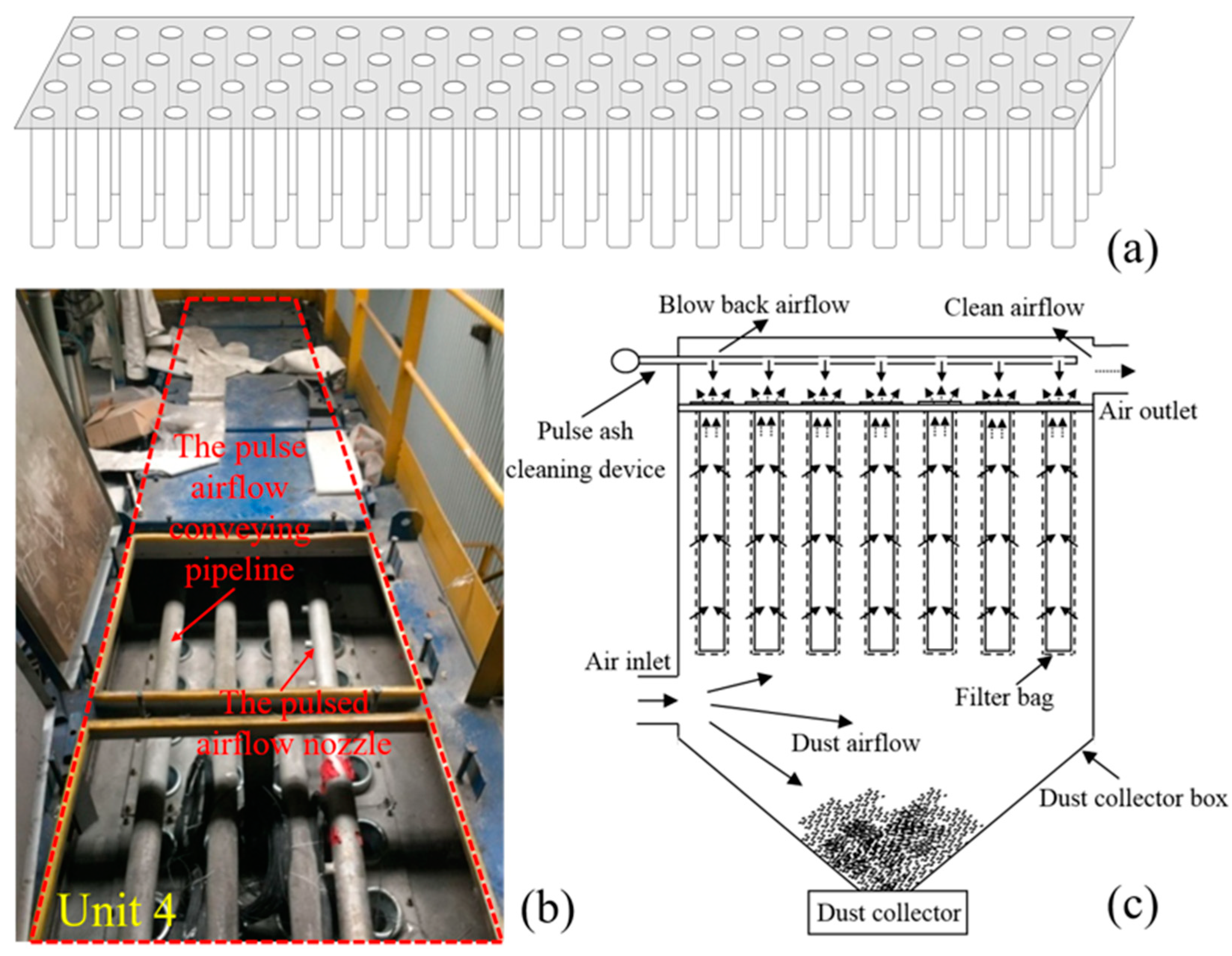
The external structure of the bag dust collector is shown in Figure 1a. The dust collector box is divided into four independent dust-cleaning chamber units, each containing 96 filter bags, which are made of acrylic needled felt. Due to the effect of pulse-jet dust-cleaning airflow, the filter bag will be damaged after a period of use, as shown in Figure 1b. The filter bag is suspended in an array within a dust-cleaning chamber unit, as shown in Figure 2a. For pulse-jet dust-cleaning bag dust collectors, an airflow pulse nozzle is usually installed above the mouth of each filter bag to clean the dust particles adhering to the filter bag’s outer wall. As shown in Figure 2b, a pulse airflow conveying duct is installed above each row of filter bags. Along the duct, an airflow pulse nozzle is installed above the mouth of each filter bag.
Figure 2c depicts the working principle of the dust collector. When the experimental device works, due to the semi-permeability of the filter cloth, airflow can pass through the filter cloth, but dust particles cannot. When the filter bag is laid inside the fiber, the airflow inside the filter bag makes the fiber cable swing, and the fiber cable is subjected to strain. This strain will be transmitted to the fiber [28,29,30], resulting in a change in the phase of the coherent optical signal inside the fiber, which produces a coherent optical signal with certain characteristics. In this paper, such a vibration signal is defined as a good bag signal. When the filter bag has a broken hole, the original airflow field inside the bag will be destroyed, the cable will be subjected to strain changes, and the phase of the coherent optical signal inside the optical fiber will also change, resulting in another kind of coherent optical signal with certain characteristics. We call this kind of vibration signal the damaged bag signal, which varies with the size and position of the broken hole. The airflow nozzle will periodically eject airflow into the mouth of the filter bag.
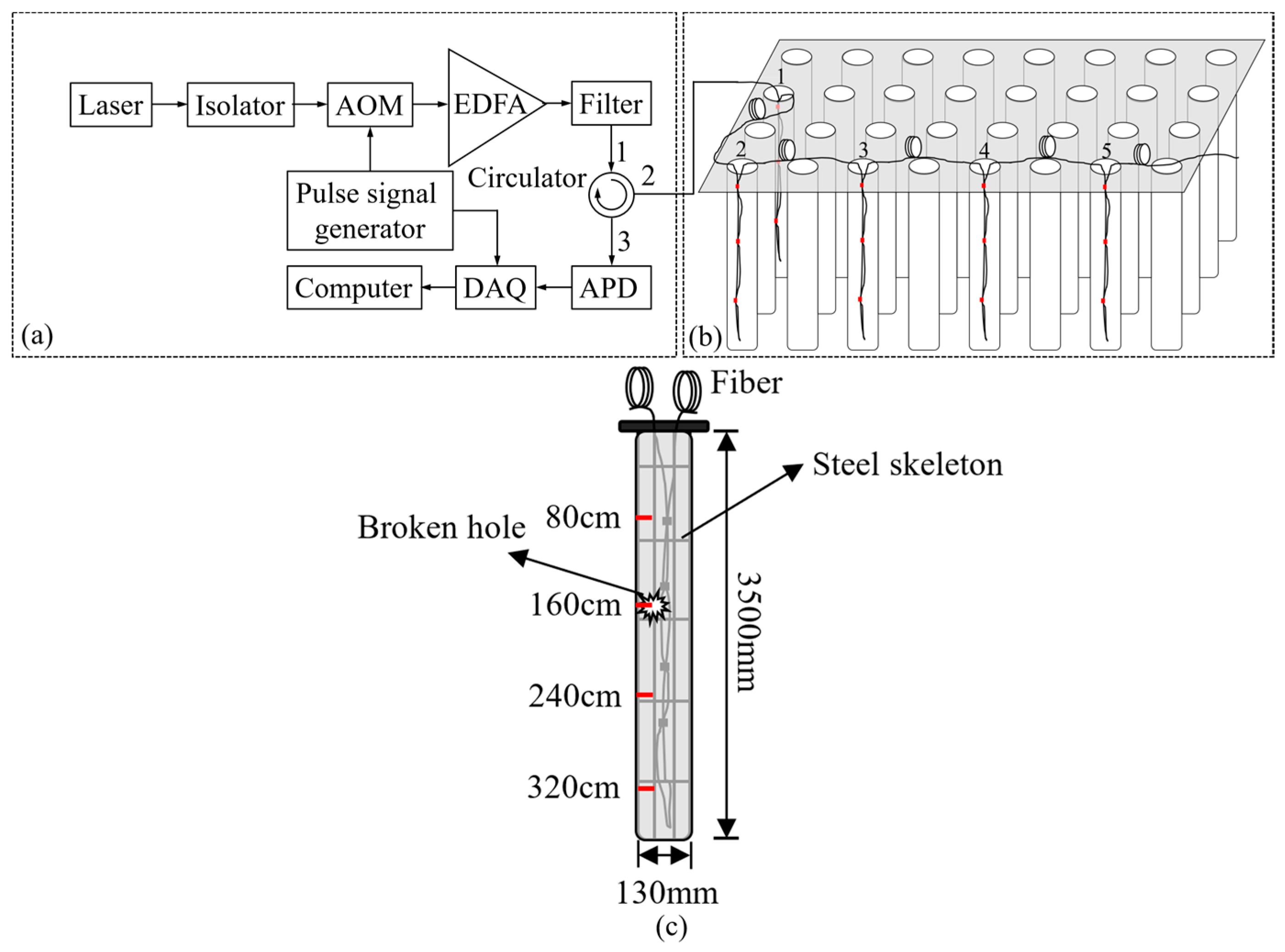
The Φ-OTDR-distributed fiber vibration sensor experimental setup is shown in Figure 3a. In order to improve the signal-to-noise ratio and localization accuracy of the Φ-OTDR sensor, our experimental setup uses a narrow linewidth laser (Koheras Basik Mikro E15, NKT Photonics, Copenhagen, Denmark), which has a low-frequency drift and a long coherence length. The laser emits continuous waves (CWs) light. After passing through the isolator, the CWs light is modulated by the acousto-optic modulator (AOM) (T-M200-0.1C2J-3-F2S, Gooch & Houseg, Ilminster, UK, AOM driver model A35200-S-1/50-P4K7u) into pulsed light. The pulsed light signal is amplified using an erbium-doped fiber amplifier (EDFA) and shaped by the filter so that it can be transmitted over longer distances in the fiber. After transferring from port 1 of the circulator, the pulsed light signal enters a 3 km long vibration fiber (SMF-28, Corning, NY, USA). Due to the Rayleigh scattering effect, the pulsed light signal will scatter CWs light in all directions. Since this scattered light signal is coherent, it will interfere and form a continuous coherent light signal. The backward coherent light signals will propagate in the reverse direction along the fiber. After entering port 2 of the circulator, they will emit from port 3 of the circulator and transform into an electronic signal via the photodetector (APD) (MODEL2053, NewFocus, San Jose, CA, USA). Finally, the signals will be collected by a customized data acquisition card (DAQ) (AD-Link PCIe-9852) and processed by the computer. The driving pulse signal required by the AOM and DAQ in the Φ-OTDR vibration signal sensor is provided by the pulse generator. When there is an intrusive interference signal along the sensing fiber link, such as various types of vibration signals, the phase of the scattered light signal at the location of the intrusive interference signal in the sensing fiber will change, resulting in a change in its coherent light intensity. After processing by a computer, the interference position can be detected. Figure 3b shows the schematic diagram of the arrangement of sensing fibers in the bag dust collector. The filter bags are arranged in an array in the dust collection box. The fibers are laid sequentially inside the filter bags, with a total of five filter bags, labeled 1, 2, 3, 4, and 5. As shown in Figure 3c, the filter bag is made of semi-permeable fabric with a diameter of 130 mm and a length of 3500 mm and is supported by a steel wire skeleton. A section of optical fiber with a length of 6 to 7 m was folded in half and secured with tape, and it was then suspended inside the filter bag being tested. The theoretical spatial resolution of the proposed sensing system is 20 m, while the actual spatial resolution measured by the experiment is 23.7 m [23]. The fiber length retained between the two filter bags must be at least 23.7 m so that the sensing system can locate each filter bag.
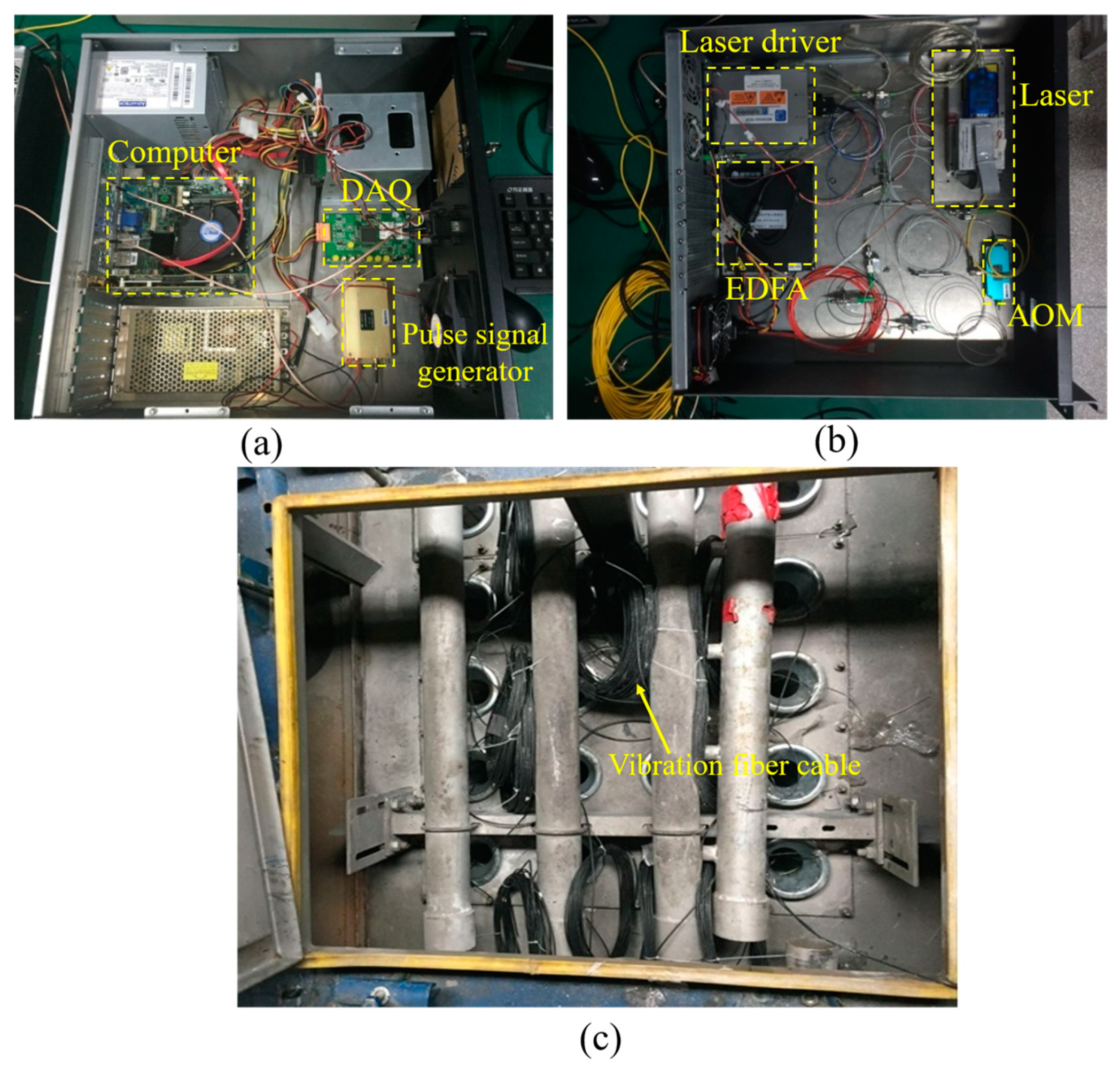
Figure 4a,b show the picture of the Φ-OTDR-distributed vibration sensor we used in our experiment. The operating wavelength and pulse width of the Φ-OTDR-distributed vibration sensor are set at 1550.12 nm and 200 ns, respectively. In order to improve the frequency response range of the detected signal, according to the Nyquist sampling theorem, the pulse-triggering repetition frequency is set to 30 kHz, and the sampling rate of the DAQ is 100 MHz. Our field test experiment was completed in a pulse-jet dust-cleaning bag dust collector test platform (Hefei Cement Research & Design Institute Corporation Ltd., Hefei, China). Figure 4c shows the picture of a dust-cleaning chamber unit in the bag dust collector test platform with vibration fiber cables laid inside each filter bag.
In our experiments, we acquired different types of filter bag vibration signals, including good bag signals and damaged bag signals with different damage states, such as different hole sizes and positions. The hole sizes are 1 cm × 10 cm, 2 cm × 10 cm, 3 cm × 10 cm, 2 cm × 8 cm, and 2 cm × 12 cm at a position of 160 cm of the filter bag. Then, we tested holes 2 cm × 10 cm in size at different positions of the filter bag, such as 80 cm, 160 cm, 240 cm, and 320 cm. The original signals of these types of filter bags are shown in Figure 5.

3. Signal Feature Analysis and Recognition

In order to identify whether a filter bag in a bag dust collector is damaged or not, we analyzed the characteristics of the undamaged bag signals and the damaged bag signals, obtained their feature differences, and then used a classifier for recognition.

3.1. Signal Feature Analysis

Compared to good bags, damaged bags are more easily penetrated by airflow, resulting in stronger vibration signals. Therefore, information energy and information entropy are used as characteristic parameters to distinguish the signal difference between a good bag and a damaged bag; the workflow of its extraction is shown in Figure 6.
The EMD algorithm is often used to analyze some non-stationary signals [31,32]. Due to the complex airflow environment inside the filter bag, the filter bag signal has obvious non-stationary characteristics, so this method is used to conduct a feature analysis of the filter bag signal, which can decompose the signal into several component IMFs. The formula can be expressed as:
x ( T n ) = i = 1 m c i ( T n ) + r ( T n )
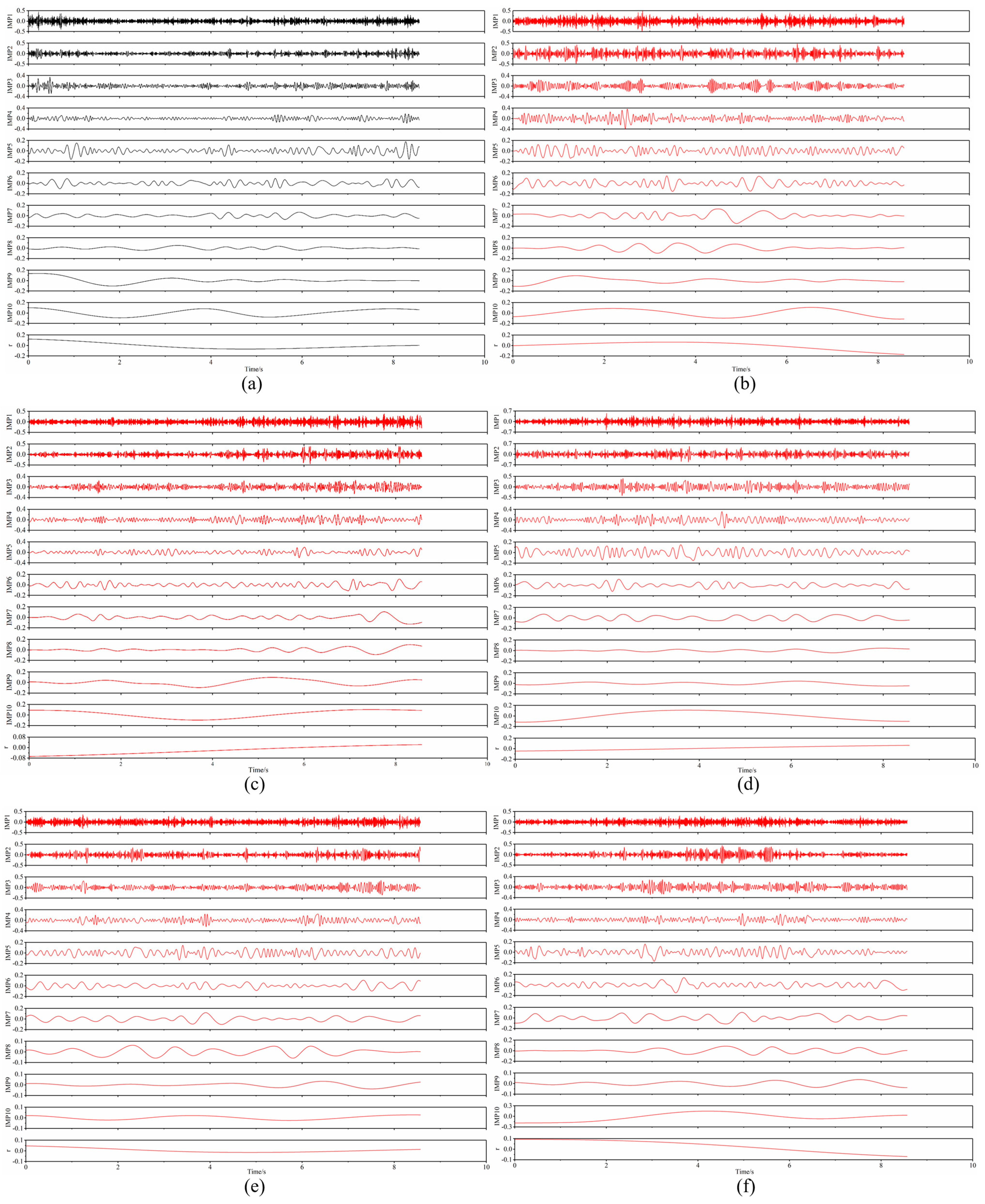
where n is the sampling index of the signal and T is the sampling period. r(Tn) is the residual error, which represents the global trend of signal x(Tn). The IMFs are denoted as c1(Tn), c2(Tn), …cm(Tn), which means that the frequencies of these mode components are sorted from high to low. Figure 7 shows the decomposition results of the good bag signal (Figure 7a) and the damaged bag signals (Figure 7b–f). There are hole sizes of 1 cm × 10 cm, 2 cm × 10 cm, 3 cm × 10 cm, 2 cm × 8 cm, and 2 cm × 12 cm, respectively, and the location is at 160 cm.
The information energy of each mode component can be expressed by Formula (2):
E i = n = 1 N c i ( T n ) 2
where N is the length of the sequence. The energy spectrum is obtained, which can be expressed as [ E 1 , E 2 , E m ] . The sum of the information energy of all mode components can be expressed as:
E s u m = i = 1 m E i
The information energy ratio is defined as the ratio of the information energy of a component to the total information energy, and the information energy ratio pi of the ith component can be expressed as:
p i = E i E s u m
Information entropy H is an important physical quantity in informatics, often used to describe the uncertainty of signals [33]. This is used to characterize the filter bag signal:
H ( x ) = i = 1 n p i log 10 p i ,   p i [ 0 , 1 ]
The unit of information entropy is dit. The information energy of each decomposition component of the good bag signal and the damaged bag signal with a broken hole size of 2 cm × 10 cm and located at 160 cm were calculated and compared. The comparison results of the information energy are shown in Figure 8. Whether it is a good bag signal or a damaged bag signal, from the high-frequency band to the low-frequency band, the trend of information energy is the same, i.e., it decreases first and then increases. Since both the good bag and the damaged bag are in the same airflow field and the filter bag is semi-permeable to airflow, the characteristics of the good bag signal and the damaged bag signal are similar. Overall, the information energy of the damaged bag signal is greater than that of the good bag signal because when the filter bag is damaged, more airflow enters inside the filter bag, so the energy of the airflow signal detected by optical fiber is higher. In addition, among all the IMF components, the information energy of the good bag signal is greater than that of the damaged bag signal only when i = 9. The reason for this result is that leakage holes cause the airflow field inside the filter bag to change, resulting in the signal characteristics of the good bag being different from those of the damaged bag. In addition, the leakage holes also significantly reduce the pressure difference between the inside and outside of the filter bag. Moreover, the EMD decomposition method will adaptively divide the frequency band of the signal according to the inherent characteristics of the signal, and the bandwidth occupied by each IMF component is not artificially determined but rather depends on the characteristics of the original signal itself. Therefore, when the signal is decomposed, the information energy of the good bag signal is higher than that of the damaged bag signal in the low band IMF9. The information entropy for both was calculated using Equation (5) and found to be 1.70 and 2.06, respectively. This indicates that the damaged bag signal is more unstable and uncertain than the good bag signal, because the holes complicate the airflow inside the filter bag.
To minimize the effect of noise, e.g., fading noise, on damaged bag recognition, a certain component is selected as the feature signal instead of using all components as feature signals. To obtain the best recognition rate, the information energy of the IMF6 component is selected as the feature parameter. An eigenvector V is constructed using the information entropy and information energy of the sixth band mode component (IMF6) of the sampled signal. This eigenvector is used to describe the characteristics of the good bag signal sample set and damaged bag signal sample set. According to the above analysis method, the eigenvalues of 150 good bag signal samples and 150 damaged bag signal samples, including each type of damaged bag, were calculated, and their distributions are shown in Figure 9. Each sub-graph in Figure 9 shows the comparison results of the vibration signal characteristics between the good filter bag and a certain type of damaged filter bag. Blue dots represent good bag signal characteristics, and red dots represent a certain type of damaged bag signal characteristics. Due to the protection of the filter bag, the airflow inside the narrow space of the good bag is more stable and definite compared to the airflow outside the filter bag. When the filter bag is damaged, the airflow inside the damaged filter bag is seriously affected by the airflow outside the filter bag, resulting in a more unstable and uncertain airflow signal inside the damaged filter bag. Therefore, in general, the information entropy of the damaged filter bag signal is higher than that of the good filter bag signal. We can see evident differences in the characteristics between them.

3.2. Filter Bag Recognition

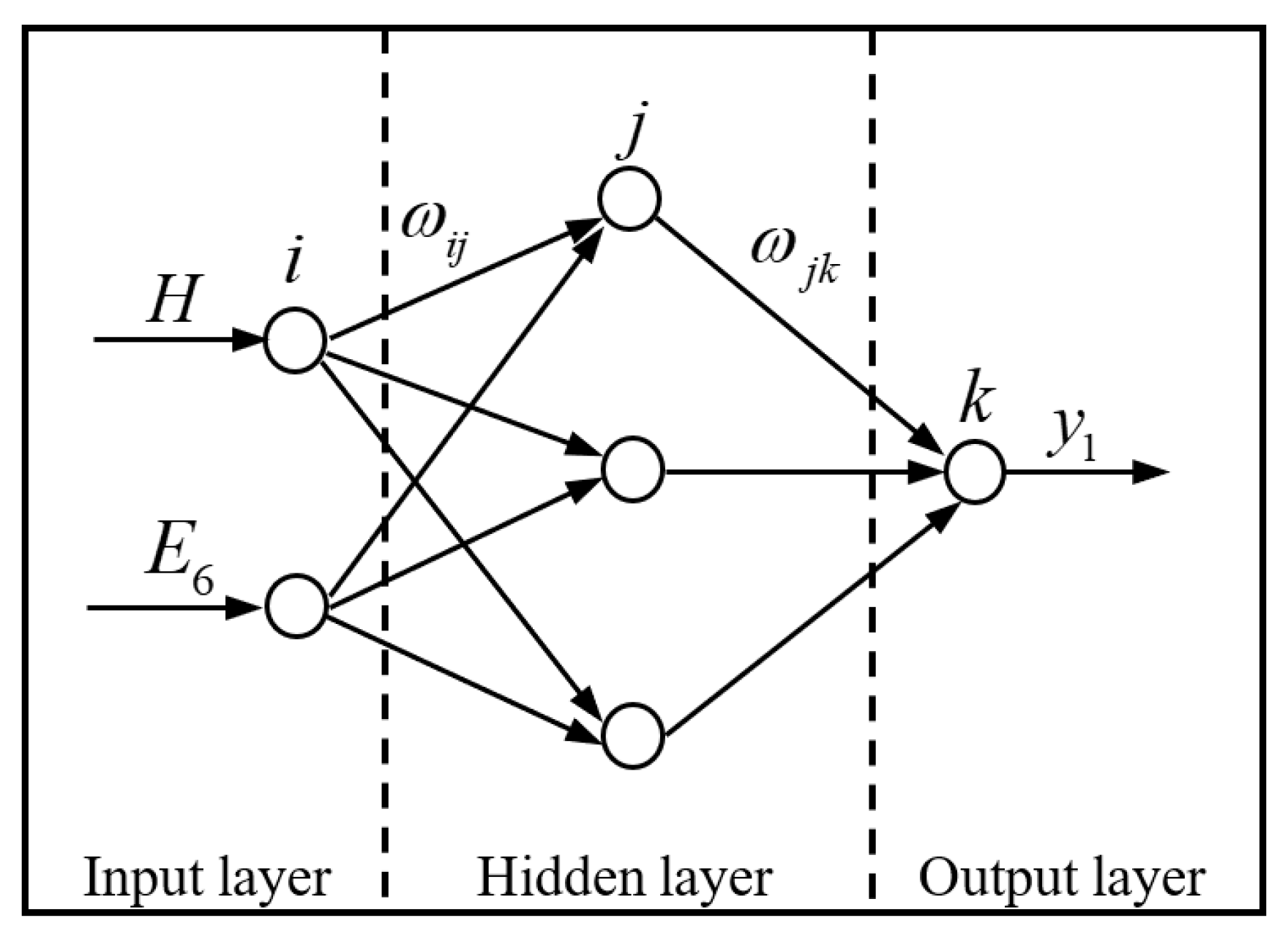
The BP neural network algorithm is used to identify good and broken filter bags in this research. As shown in Figure 10, the BP neural network adopts a three-level network topology structure, i.e., it includes an input level, a concealment level, and an output level. The input level has two neurons, which represent the information entropy and the information energy of the sixth band mode component (IMF6) of the sampled signal. The choice of two-dimensional parameters is based on the conclusions analyzed from the above results. In the concealed level, we set up three neurons. wij denotes the connection weight from the ith point in the input level to the jth point to the concealed level. The output level has one neuron, representing the filter bag recognition result output by the network. The filter bag recognition rate refers to the ratio of the number of filter bag feature samples correctly recognized by the recognition classifier to the total number of filter bag feature samples input to the recognition classifier. The number of filter bag feature samples includes the number of damaged bag feature samples and the number of good bag feature samples. wjk denotes the connection weight from the jth point in the concealed level to the kth point in the output level. For the comparative analysis, we also used an SVM classifier to recognize the filter bags. In the recognition process, SVM and BP algorithms are used on the same samples during training and testing, i.e., the same training sample set is input into the SVM and BP models for training, and the same test sample set is input into the SVM and BP models for recognition.
We used SVM and BP classifiers to analyze the sample set contained in each data map in Figure 9. In order to calculate the recognition rate of damaged filter bags, a training sample set consisting of 100 samples was randomly extracted from the total sample set of 300 samples, which consisted of 50 good bag samples and 50 damaged bag samples. These samples were used to train the recognition classifier. After good training, the 200 remaining test samples, including 100 good bag samples and 100 damaged bag samples, were fed into the classifier for pattern recognition.
In the recognition test, in order to make the recognition results more credible when calculating the recognition rate of each filter bag sample, the samples were analyzed 10 times consecutively, and then their average value was calculated. This value is called the average identification rate. The detailed identification results of each type of filter bag are shown in Table 1 and Table 2. It can be seen from the two tables that the BP neural network has a higher average identification rate of filter bags compared to the SVM classifier, with an average recognition rate of up to 97.3% for the proposed method. As shown in Table 1, the average bag recognition rate is below 90% when the SVM classifier is used, while the average bag recognition rate is more than 90% when the BP neural network is used. When the length or width remains unchanged, the larger the size of the hole, the higher the recognition rate. Moreover, the length of the filter bag has a greater impact on the recognition rate compared to the width of the filter bag.
In Table 2, when the size of the hole remains unchanged and its position is closer to the filter bag bottom, a higher recognition rate can be achieved. Since the fiber is suspended on the filter bag, it induces a single pendulum vibration under the action of airflow. Under the same conditions of airflow pressure, compared to the circumferential disturbance factor of the leaky hole, the axial disturbance factor has a greater impact on the single pendulum vibration for the cylindrical filter bag. Longer and lower hole positions will cause more severe vibration of the fiber pendulum, resulting in higher recognition rates.

3.3. Damaged Filter Bag Localization and Alarm Method

Fiber can be laid inside a bag dust collector in two ways. As shown in Figure 11a, one method is to use a single fiber to connect all filter bags, which is also the method used in this paper. The other method is to lay the fibers in parallel inside the bag dust collector, where all the bags in the same row or column are connected in series with a single fiber. All these fibers are connected to the Φ-OTDR distributed fiber vibration sensing system via a fiber interface scanning switch. During operation, the sensing system sequentially scans the filter bags on each row or column, as shown in Figure 11b.
When locating the damaged filter bag, each filter bag is numbered and noted as 1, 2, …, I, which all correspond one-to-one with a location point on the sensing fiber, and the distances corresponding to the position points of each filter bag along the fiber link are recorded as L1 m, L2 m, …, Li m, respectively. When the filter bag is broken, the vibration signal of the fiber placed inside the filter bag will change. The Rayleigh trace curve after multiple overlays will show a peak at the location of the filter bag [25]. We choose the time-domain vibration signal of the peak position point to characterize the filter bag signal. For example, in this paper, the distance of the filter bag is 1526 m when the filter bag signal is collected. The fiber distance between any two filter bags must be greater than the actual spatial resolution of the sensing system. The filter bag can be monitored in real-time using either the serial scanning method or the parallel scanning method. As shown in Figure 12a, when using the serial scanning method, the data processing program scans each marked position point along the sensing fiber line one by one. Assuming the fiber position point corresponding to the filter bag is marked as i, when the data processing program scans the position point, it extracts the time-domain vibration signal of the fiber position point for some time and divides it into several equal parts according to time, forming a large number of vibration signal samples. The time-domain vibration signal samples are recognized according to the feature extraction and pattern recognition algorithm proposed in this paper, and the average recognition rate is output. Set the alarm threshold according to the engineering application requirements. If the average recognition rate is less than the threshold, the system does not alarm, indicating that the filter bag is not damaged in the bag dust collector at this time; if the average recognition rate is greater than the threshold, the system alarms, indicating that the filter bag is broken in the bag dust collector at this time. After processing the ith position point, continue to process the i + 1th fiber position point, and so on. When using the parallel scanning method, the data processing program synchronously scans each marked position point along the sensing fiber line, synchronously extracts the time-domain vibration signal of each position point for some time, processes it, outputs the average recognition rate, and alarms in the same way as the serial method.

4. Discussion

To further validate the practicability of the filter bag identification scheme proposed in this paper, the leaky bag identification rate was further analyzed using quantitative analysis. The mixed filter bag signal samples can be divided into three categories. Type I is defined as a mixed filter bag signal sample, including good bag signals and damaged bag signals, where the hole widths vary between 1 cm, 2 cm, and 3 cm, while the hole length and location remain unchanged, at 10 cm and 160 cm, respectively. Type II is defined as a mixed filter bag signal sample, including good bag signals and damaged bag signals, where the broken hole lengths vary between 8 cm, 10 cm, and 12 cm, respectively, while its width and location remain unchanged, at 2 cm and 160 cm, respectively. Type III is defined as a mixed filter bag signal sample, including good bag signals and damaged bag signals, where the broken hole locations vary between 80 cm, 160 cm, 240 cm, and 320 cm, respectively, while its length and width remain unchanged, at 10 cm and 2 cm, respectively. For each type of event in the recognition process, 100 samples, including 50 good bag samples and 50 damaged bag samples, were used as training samples, and the remaining samples were used for testing. Each mixed filter bag signal sample was analyzed 10 times, and then the average value was calculated. Table 3 outlines the identification results.
Finally, to demonstrate the versatility of the proposed filter bag identification program, 100 mixed filter bag training samples, including 50 damaged bag training samples and 50 good bag training samples, were used to train the recognition classifier. The hole size and hole location of the damaged bag training samples are 2 cm × 10 cm and 80 cm, respectively. All the remaining filter bag samples were mixed to form a mixed-test sample called Type VI. The recognition results obtained by inputting the mixed-test sample into the SVM classifier and the BP neural network are shown in Table 3. It can be seen that the BP neural network can still recognize the filter bag efficiently. The BP neural network is also more efficient than the SVM classifier, with an average recognition rate of up to 95.9%. This shows that the method has some versatility in baghouse filter bag identification.

5. Conclusions

In summary, a method for detecting and recognizing rectangular damaged filter bags in pulse-jet dust-cleaning bag dust collectors has been proposed. Different filter bag signals were decomposed using EMD. The information energy and information entropy of the signals were calculated and used as the feature parameters to comparatively analyze the signal feature differences between good filter bags and leaky filter bags with different rectangular hole sizes and locations. The results show that the two-dimensional feature parameter combined with the information energy of the sixth component and signal information entropy is the best feature difference parameter. An SVM and a BP neural network were used to recognize different types of filter bag signals, and the comparison results show that the BP neural network algorithm can better recognize different types of filter bags, obtaining the highest recognition rate of 97.3%. The length and position of a hole have a great influence on the recognition rate; the width of the hole has a smaller effect on the recognition rate. This identification method has some reference value in the engineering application of using Φ-OTDR-distributed fiber vibration sensors to identify damaged bags in pulse-jet dust-cleaning bag dust collectors. In future research, we will focus on two aspects. First, we will optimize the structure of the sensing system to enhance its performance. Second, we will improve the algorithm to eliminate the influence of noise on the detection signal, enhance its signal-to-noise ratio, and improve the quality of the feature differences between the good bag signal and the broken bag signal. For example, using the Variational Mode Decomposition (VMD) algorithm to process the detection signal more deeply.

Author Contributions

Conceptualization, X.L., Z.Z., Y.T. and S.Y.; methodology, X.L. and Z.Z.; software, X.L.; investigation, X.L. and S.Y.; resources, X.L., Z.Z., Y.T. and S.Y.; data curation, X.L. and Z.H.; writing—original draft preparation, X.L.; writing—review and editing, X.L., Z.Z. and Y.X.; supervision, X.L. and Z.Z.; project administration, X.L., Y.T., S.Y. and Z.H.; funding acquisition, X.L., S.Y. and Y.X. All authors have read and agreed to the published version of the manuscript.

Funding

This research was funded by the Natural Science Research Project of Anhui Province Education Department, grant numbers 2022AH051958 and 2022AH051957. The Start-up Fund of Huangshan University, grant number 2020xkjq015. The Teaching Quality Project of Mount Huangshan University, grant number 2022JXYJ36. The Hefei Municipal Natural Science Foundation—National Natural Science Foundation of Hefei, grant numbers 202331, 202335, and 202339. The “Spark” Fund Project of Hefei Institutes of Physics Science, Chinese Academy Sciences, grant number YZJJ2022QN02. And the Open Project Program of Guangdong Provincial Key Laboratory of Intelligent Disaster Prevention and Emergency Technologies for Urban Lifeline Engineering, grant number 2022ZA03.

Institutional Review Board Statement

Not applicable.

Informed Consent Statement

Not applicable.

Data Availability Statement

All data are provided in full in the Results section of this paper.

Acknowledgments

The authors would like to thank their supervisors and colleagues who have helped considerably with this research.

Conflicts of Interest

The authors declare no conflicts of interest.

References

  1. Zhang, M.; Li, Y.; Chen, J.; Song, Y.; Zhang, J.; Wang, M. Event detection method comparison for distributed acoustic sensors using φ-OTDR. Opt. Fiber Technol. 2019, 52, 101980–101986. [Google Scholar] [CrossRef]
  2. Li, Z.; Zhang, J.; Wang, M.; Chai, J.; Wu, Y.; Peng, F. An anti-noise ϕ-OTDR based distributed acoustic sensing system for high-speed railway intrusion detection. Laser Phys. 2020, 30, 085103–085110. [Google Scholar] [CrossRef]
  3. Marie, T.F.B.; Bin, Y.; Dezhi, H.; Bowen, A. Principle and Application State of Fully Distributed Fiber Optic Vibration Detection Technology Based on Φ-OTDR: A Review. IEEE Sens. J. 2021, 21, 16428–16442. [Google Scholar] [CrossRef]
  4. Wang, Z.; Lu, B.; Ye, Q.; Cai, H. Recent progress in distributed fiber acoustic sensing with Φ-OTDR. Sensors 2020, 20, 6594. [Google Scholar] [CrossRef] [PubMed]
  5. Zhu, H.; Pan, C.; Sun, X. Vibration pattern recognition and classification in OTDR based distributed optical-fiber vibration sensing system. In Proceedings of the SPIE, San Diego, CA, USA, 9–13 March 2014; Volume 9062, p. 906205. [Google Scholar] [CrossRef]
  6. Zhang, Y.; Lou, S.; Liang, S.; Wang, P. Study of pattern recognition based on multi-characteristic parameters for Φ-OTDR distributed optical fiber sensing system. Chin. J. Lasers 2015, 42, 1105005–1105013. [Google Scholar] [CrossRef]
  7. Xu, W.; Yu, F.; Liu, S.; Xiao, D.; Hu, J.; Zhao, F.; Lin, W.; Wang, G.; Shen, X.; Wang, W.; et al. Real-Time Multi-Class Disturbance Detection for Φ-OTDR Based on YOLO Algorithm. Sensors 2022, 22, 1994. [Google Scholar] [CrossRef]
  8. Yang, N.; Zhao, Y.; Chen, J.; Wang, F. Real-time classification for Φ-OTDR vibration events in the case of small sample size datasets. Opt. Fiber Technol. 2023, 76, 103217–103228. [Google Scholar] [CrossRef]
  9. Wu, H.; Liu, X.; Xiao, Y.; Rao, Y.-J. A Dynamic Time Sequence Recognition and Knowledge Mining Method Based on the Hidden Markov Models (HMMs) for Pipeline Safety Monitoring with Φ-OTDR. J. Light. Technol. 2019, 37, 4991–5000. [Google Scholar] [CrossRef]
  10. Stajanca, P.; Chruscicki, S.; Homann, T.; Seifert, S.; Schmidt, D.; Habib, A. Detection of Leak-Induced Pipeline Vibrations Using Fiber-Optic Distributed Acoustic Sensing. Sensors 2018, 18, 2841. [Google Scholar] [CrossRef]
  11. Tejedor, J.; Macias-Guarasa, J.; Martins, H.F.; Piote, D.; Pastor-Graells, J.; Martin-Lopez, S.; Corredera, P.; Gonzalez-Herraez, M. A Novel Fiber Optic Based Surveillance System for Prevention of Pipeline Integrity Threats. Sensors 2017, 17, 355. [Google Scholar] [CrossRef]
  12. Peng, F.; Duan, N.; Rao, Y.-J.; Li, J. Real-Time Position and Speed Monitoring of Trains Using Phase-Sensitive OTDR. IEEE Photonics Technol. Lett. 2014, 26, 2055–2057. [Google Scholar] [CrossRef]
  13. Wang, Z.; Zheng, H.; Li, L.; Liang, J.; Wang, X.; Lu, B.; Ye, Q.; Qu, R.; Cai, H. Practical multi-class event classification approach for distributed vibration sensing using deep dual-path network. Opt. Express 2019, 27, 23682–23692. [Google Scholar] [CrossRef]
  14. Milne, D.; Masoudi, A.; Ferro, E.; Watson, G.; Le Pen, L. An analysis of railway track behavior based on distributed optical fiber acoustic sensing. Mech. Syst. Signal Process. 2020, 142, 106769–106790. [Google Scholar] [CrossRef]
  15. Yang, N.; Zhao, Y.; Chen, J. Real-Time Φ-OTDR Vibration Event Recognition Based on Image Target Detection. Sensors 2022, 22, 1127. [Google Scholar] [CrossRef]
  16. Xie, Y.; Wang, M.; Zhong, Y.; Deng, L.; Zhang, J. Label-Free Anomaly Detection Using Distributed Optical Fiber Acoustic Sensing. Sensors 2023, 23, 4094. [Google Scholar] [CrossRef] [PubMed]
  17. Fernández-Ruiz, M.R.; Soto, M.A.; Williams, E.F.; Martin-Lopez, S.; Zhan, Z.; Gonzalez-Herraez, M.; Martins, H.F. Distributed acoustic sensing for seismic activity monitoring. APL Photonics 2020, 5, 030901–030917. [Google Scholar] [CrossRef]
  18. Daley, T.; Miller, D.; Dodds, K.; Cook, P.; Freifeld, B. Field testing of modular borehole monitoring with simultaneous distributed acoustic sensing and geophone vertical seismic profiles at Citronelle, Alabama. Geophys. Prospect. 2016, 64, 1318–1334. [Google Scholar] [CrossRef]
  19. Byerley, G.; Monk, D.; Aaron, P.; Yates, M. Time-lapse seismic monitoring of individual hydraulic frac stages using a downhole DAS array. Lead. Edge 2018, 37, 802–810. [Google Scholar] [CrossRef]
  20. Hubbard, P.G.; Xu, J.; Zhang, S.; Dejong, M.; Luo, L.; Soga, K.; Papa, C.; Zulberti, C.; Malara, D.; Fugazzotto, F.; et al. Dynamic structural health monitoring of a model wind turbine tower using distributed acoustic sensing (DAS). J. Civil. Struct. Health Monit. 2021, 11, 833–849. [Google Scholar] [CrossRef]
  21. Zahoor, R.; Cerri, E.; Vallifuoco, R.; Zeni, L.; De Luca, A.; Caputo, F.; Minardo, A. Lamb Wave Detection for Structural Health Monitoring Using a ϕ-OTDR System. Sensors 2022, 22, 5962. [Google Scholar] [CrossRef] [PubMed]
  22. Zahoor, R.; Catalano, E.; Vallifuoco, R.; Zeni, L.; Minardo, A. Automated Damage Detection Using Lamb Wave-Based Phase-Sensitive OTDR and Support Vector Machines. Sensors 2023, 23, 1099. [Google Scholar] [CrossRef] [PubMed]
  23. Gao, G.; Li, J.; Liu, X.; Shi, B.; Tang, Y.; Pang, T.; Zheng, Q.; Sun, L.; Dong, F. Bag Filter Leak Detection and Location Based on Phase-Sensitive Optical Time Domain Reflectometry. ACTA Opt. Sin. 2018, 38, 0706001–0706009. [Google Scholar] [CrossRef]
  24. Li, J.; Lu, X.; Wang, W. Leak monitoring and localization in baghouse filtration system using a distributed optical fiber dynamic air pressure sensor. Opt. Fiber Technol. 2020, 57, 102218–102229. [Google Scholar] [CrossRef]
  25. Liu, X.; Li, J.; Shi, B.; Ding, G.; Dong, F.; Zhang, Z. Intelligent detection technology for leakage bag of baghouse based on distributed optical fiber sensor. Opt. Fiber Technol. 2019, 52, 101947–101955. [Google Scholar] [CrossRef]
  26. Mukhopadhyay, A.; Mahawar, G. Effect of leaks on performance of a fabric filter in pulse jet cleaning assisted filtration system. Indian J. Fibre Text. Res. (IJFTR) 2020, 45, 326–331. [Google Scholar] [CrossRef]
  27. Zhou, R.; Shen, H.; Zhao, M. Simulation studies on protector of pulse-jet cleaning filter bag. Energy Procedia 2012, 16, 426–431. [Google Scholar] [CrossRef]
  28. Wang, H.; Xiang, P.; Jiang, L. Strain transfer theory of industrialized optical fiber-based sensors in civil engineering: A review on measurement accuracy, design and calibration. Sens. Actuators A Phys. 2019, 285, 414–426. [Google Scholar] [CrossRef]
  29. Wang, H.; Jiang, L.; Xiang, P. Improving the durability of the optical fiber sensor based on strain transfer analysis. Opt. Fiber Technol. 2018, 42, 97–104. [Google Scholar] [CrossRef]
  30. Wang, H.; Jiang, L.; Xiang, P. Priority design parameters of industrialized optical fiber sensors in civil engineering. Opt. Laser Technol. 2018, 100, 119–128. [Google Scholar] [CrossRef]
  31. Huang, N.E.; Shen, Z.; Long, S.R.; Wu, M.C.; Shih, H.H.; Zheng, Q.; Yen, N.-C.; Tung, C.C.; Liu, H.H. The empirical mode decomposition and Hilbert spectrum for non-linear and non-stationary time series analysis. Proc. R. Soc. A 1998, 454, 903–995. [Google Scholar] [CrossRef]
  32. Rehman, N.U.; Mandic, D.P. Empirical Mode Decomposition for Trivariate Signals. IEEE Trans. Signal Process. 2010, 58, 1059–1068. [Google Scholar] [CrossRef]
  33. Huang, J.; Hu, X.; Geng, X. An intelligent fault diagnosis method of high voltage circuit breaker based on improved EMD energy entropy and multi-class support vector machine. Electr. Power Syst. Res. 2011, 81, 400–407. [Google Scholar] [CrossRef]
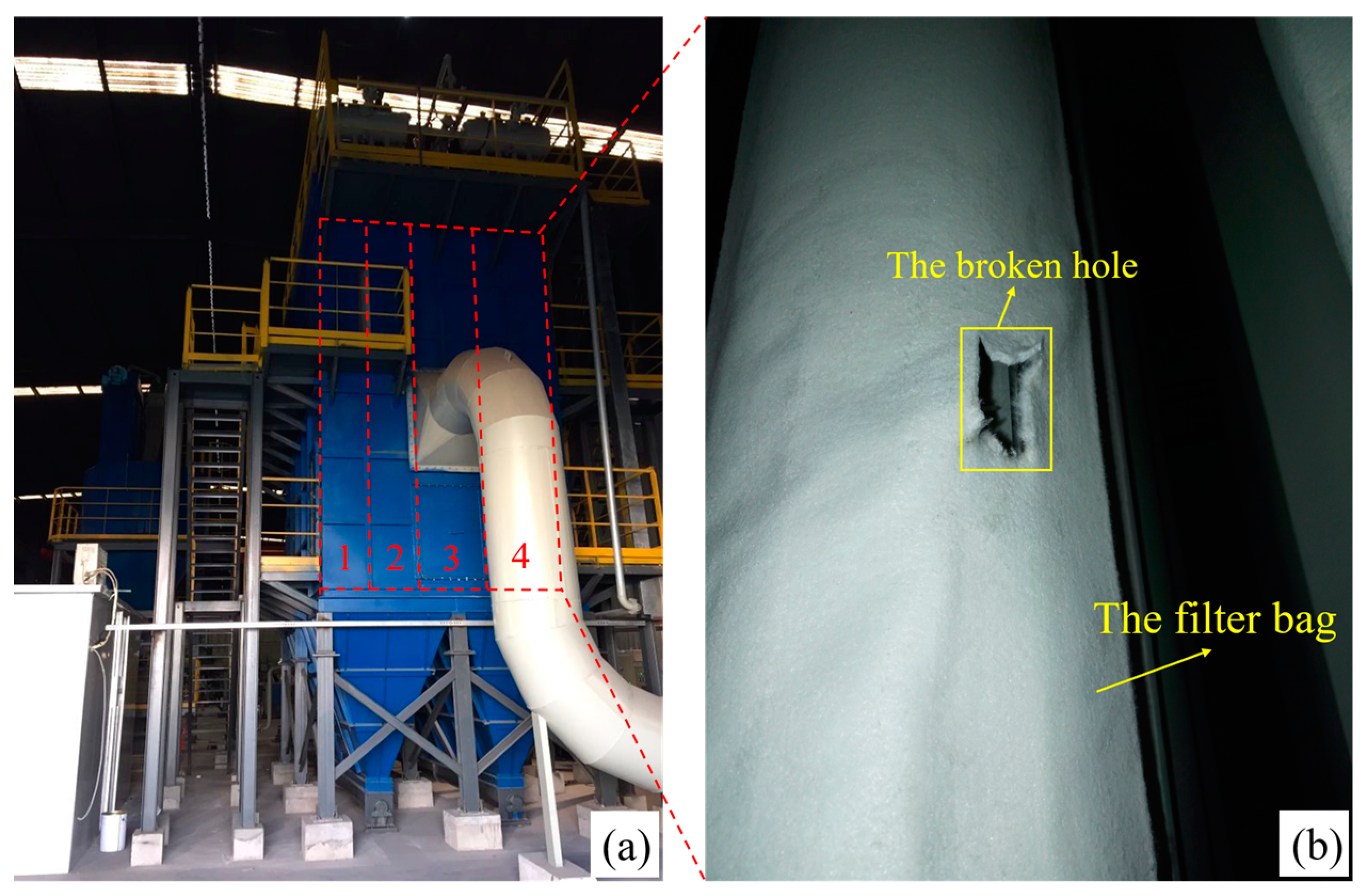
Figure 1. (a) The external structure of the bag dust collector used in this experiment. (b) The filter bags and the broken hole of a filter bag in a dust-cleaning chamber unit of the dust collector.
Photonics 11 00152 g001
Figure 2. (a) Schematic diagram of the filter bag in a dust-cleaning chamber unit. (b) Picture of dust-cleaning chamber unit 4 used in the experiment. (c) Working principle diagram of the pulse-jet dust-cleaning bag dust collector.
Photonics 11 00152 g002
Figure 3. (a) The Φ-OTDR-distributed fiber vibration sensor experimental setup. AOM: acoustic optical modulator; EDFA: erbium-doped fiber amplifier; APD: avalanche photodiode; DAQ: data acquisition. (b) Schematic diagram of the Φ-OTDR vibration signal sensor deployment method in the bag dust collector. (c) Schematic diagram of the filter bag structure we used in this experiment.
Photonics 11 00152 g003
Figure 4. (a,b) Pictures of the Φ-OTDR-distributed fiber vibration sensor experimental setup. (c) Picture of a dust-cleaning chamber unit in the bag dust collector test platform with vibration fiber cables laid inside each filter bag at Hefei Cement Research & Design Institute Corporation Ltd. test platform.
Photonics 11 00152 g004
Figure 5. The original vibration signal sampled by the experimental setup. (a) Good bag; (bi) different kinds of damaged bag.
Photonics 11 00152 g005
Figure 6. Processing flow of energy spectrum and information entropy extraction based on EMD.
Photonics 11 00152 g006
Figure 7. The IMF components of the sampled fiber vibration signals decomposed by the EMD method. (a) Good bag; (bf) damaged bag. There are broken hole sizes of 1 cm × 10 cm, 2 cm × 10 cm, 3 cm × 10 cm, 2 cm × 8 cm, and 2 cm × 12 cm, respectively, and the location is at 160 cm.
Photonics 11 00152 g007
Figure 8. Comparison of the information energy of the good bag versus the damaged bag. The bro hole size is 2 cm × 10 cm, and the location is 160 cm.
Photonics 11 00152 g008
Figure 9. Distribution of vibration signal characteristic parameters of good bag with 150 samples and different types of damaged bag with 150 samples, and the parameters of the broken holes are as follows: (a) the hole size is 2 cm × 8 cm, and the location is 160 cm; (b) the hole size is 2 cm × 10 cm, and the location is 160 cm; (c) the hole size is 2 cm × 12 cm, and the location is 160 cm; (d) the hole size is 1 cm × 10 cm, and the location is 160 cm; (e) the hole size is 3 cm × 10 cm, and the location is 160 cm; (f) the hole size is 2 cm × 10 cm, and the location is 80 cm; (g) the hole size is 2 cm × 10 cm, and the location is 240 cm; and (h) the hole size is 2 cm × 10 cm, and the location is 320 cm.
Photonics 11 00152 g009aPhotonics 11 00152 g009b
Figure 10. Three-layer BP neural network for filter bag classification.
Photonics 11 00152 g010
Figure 11. (a) Schematic diagram of single fiber laid in series. (b) Schematic diagram of multiple fibers laid in parallel.
Photonics 11 00152 g011
Figure 12. Flowchart for locating, identifying, and alarming damaged filter bags. (a) The serial scanning method. (b) The parallel scanning method.
Photonics 11 00152 g012
Table 1. The filter bag recognition rates for different broken hole sizes at the position of 160 cm.
Filter Bag2 cm × 8 cm2 cm × 10 cm2 cm × 12 cm1 cm × 10 cm3 cm × 10 cm
Recognition
rate
SVMBPSVMBPSVMBPSVMBPSVMBP
87.5%93.5%88%94%89.5%94.5%80%94.5%82.5%93.5%
88.5%91%82%93.5%90.5%96.5%86%94.5%89.5%96%
85%90%88.5%95.5%89%97.5%90%95%83%93.5%
83.5%94%83%94%91.5%98.5%87.5%94%87%95.5%
89.5%91.5%86.5%91.5%87.5%94.5%84%94.5%90%95%
81.5%95%89%95.5%87.5%98%91%92%86%95.5%
83%91.5%87%93.5%90%96.5%86%92%81.5%95.5%
82.5%91.5%81.5%94%90.5%95%83.5%94.5%84.5%92%
89%91%88.5%96.5%91%97.5%91.5%94%90.5%95%
81%92.5%87%95.5%86%94%87%94%89.5%96%
Average recognition rate85.1%92.2%86.1%94.4%89.3%96.3%86.7%93.9%86.4%94.8%
Table 2. The filter bag recognition rates for different broken hole positions with a broken hole size of 2 cm × 10 cm.
Filter Bag80 cm160 cm240 cm320 cm
Recognition
rate
SVMBPSVMBPSVMBPSVMBP
86.5%93.5%88%94%86.5%96.5%91.5%99%
86.5%91.5%82%93.5%88%96%91%99%
87.5%91.5%88.5%95.5%90%96%90.5%95.5%
90%93.5%83%94%92%96%90.5%98.5%
91.5%92%86.5%91.5%90%93%92.5%97.5%
85.5%92.5%89%95.5%86.5%94.5%90.5%98%
86.5%94%87%93.5%91.5%96.5%90%99%
82.5%92.5%81.5%94%86.5%95%93%97%
87.5%92%88.5%96.5%87.5%96%89.5%92%
84.5%92.5%87%95.5%94%97.5%88.5%97.5%
Average recognition rate86.9%92.6%86.1%94.4%89.3%95.7%90.8%97.3%
Table 3. The filter bag recognition rate of mixed samples with different leakage states.
Mixed Filter BagIIIIIIIV
Recognition
rate
SVMBPSVMBPSVMBPSVMBP
90.1%92.6%83%95.8%92.5%92.3%90.4%95.3%
86.9%95.4%87%96.4%87.2%92.5%90.8%96%
90.9%94.2%88%96.8%88.3%95.8%89.2%96.3%
89%92.6%89.4%96.8%90.5%92.8%89%94%
89.4%95.8%89.8%97.6%91.1%94.5%90.4%95.6%
90.4%91.8%87.1%96.4%90.4%95.4%88.9%96.5%
90.9%93%84.8%93.6%90%95.5%87.3%95.5%
88.5%92.4%84.4%95.8%89.3%96.2%88.6%96.3%
87.9%91.8%89.1%93.2%88.1%94.9%89.5%95.6%
87%93%87.9%96.8%88.5%96.6%88.5%97.3%
Average recognition rate89.1%93.3%87.1%95.9%89.6%94.7%89.3%95.8%
I: Type I—samples of good filter bags and damaged filter bags with different hole widths and same length and location; II: Type II—samples of good filter bags and damaged filter bags with different hole lengths and same width and location; III: Type III—samples of good filter bags and damaged filter bags with different hole locations and same width and length; IV: Type IV—samples of good filter bags and damaged filter bags with different hole locations, widths, and length.
Disclaimer/Publisher’s Note: The statements, opinions and data contained in all publications are solely those of the individual author(s) and contributor(s) and not of MDPI and/or the editor(s). MDPI and/or the editor(s) disclaim responsibility for any injury to people or property resulting from any ideas, methods, instructions or products referred to in the content.