Abstract
Boosting the harmonic generation of light in nanostructures through efficiently enhancing the light–matter interaction has received enormous attention and applications. Low-index dielectric nanoparticles, as one of the crucial members of nanophotonics, have not been successful in nonlinear enhancement due to weak Mie resonance and poor light confinement. Here, we designed efficient third harmonic generation (THG) in low-index dielectric nanopillars sandwiched by double layers of metal dressing (Au/polymer/Au), where the polymer offers essential nonlinear susceptibility. The resonance of the low-index nanopillars significantly enhanced the scattering and had a strong magnetic response that could boost the THG effect. We predict that the THG efficiency reaches up to 3 × 10⁻⁶ (six orders of enhancement) at a third harmonic wavelength of 300 nm. The efficient THG in low-index dielectric nanopillars may open the possibility for the development of a new type of efficient nonlinear coherent source.
1. Introduction
Nonlinear nanophotonics has attracted a lot of attention and benefits applications [1] including nanolasers [2], nonlinear spectroscopy [3], biosensing [4,5], optoelectronic devices [6], and quantum information processing [7]. Due to the high field enhancement and strong resonances, the small volume of nanoparticles like metallic and high-index dielectric ones can achieve a strong nonlinear response [8,9,10,11]. For plasmonic nanostructures, enhanced nonlinear effects originate from several effects or their combinations [12,13], including localized surface plasmon resonances enhancement [14,15], symmetry breaking [16,17], and surface lattice resonance [18]. High Ohmic losses, however, prevent the advancement of plasmonics. High-index dielectric nanoparticles serve as a platform for nonlinear effects due to the intrinsic low absorption losses and the capacity to support localized electric and magnetic Mie-type modes [9,19,20]. Third harmonic generation (THG) has been substantially improved in nanostructures constructed from high-index semiconductors, such as Si [21,22], Ge [23], and TiO2 [24]. The high nonlinear efficiency has been driven by electric and magnetic Mie-type resonances [25], bound states in the continuum on dielectric metasurfaces [26,27,28], and nonradiating anapole excitations [24,29]. Additionally, hybrid structures that combine dielectric and metal materials enable one to avoid restrictions and show promise as a superior platform for a variety of nonlinear optical processes [30,31,32,33].
Low-index dielectric nanoparticles are currently a basic intense research topic, along with SiO2 and polystyrene nanoparticles, and they have more applications than their metallic and high-index dielectric counterparts. The application scope covers drug delivery [34,35], biology [36,37], superhydrophobic nanocoatings [38,39], and others and has easy and low-cost large-scale preparation characteristics. However, because of poor light confinement brought on by small index contrast with the surrounding environment, it is typically difficult for low-index dielectric nanoparticles to sustain efficient resonant scattering characteristics. In 2018, W. Li et al. experimentally demonstrated strong Mie resonance in low-index nanoparticles by partial metal dressing [40]. The work overcame the restriction of low-efficient Mie resonance in low-index nanoparticles and opened up a wider range of potential uses. Utilizing the switchable Mie resonance mode, all-state switching has recently been accomplished in conductive polymer nanospheres [41]. These results significantly broaden the uses of low-index dielectric nanoparticles as fundamental optical components [42]. Nonlinear effects from low-index dielectric material have been studied in an organic conjugated polymer [43] and hybrid organic–plasmonic nanoantennas [44]. However, there is limited research on nonlinear effects in low-index nanoparticles. Compact and ultrafast optical systems will become possible by advancing the linear optical effect in low-index dielectric nanoparticles to nonlinear areas.
In this study, nonlinear harmonic generation in low-index nanoparticles with strong resonances was investigated, and we theoretically demonstrate that THG can significantly increase efficiency by sandwiching low-index polymer nanopillars between two layers of metal dressing. The nonlinear polymer (refractive index n = 1.5, χ(3) = 4 × 10⁻¹⁸ m2/V2 at wavelength 900 nm) offers the necessary nonlinear susceptibility. The metal dressing provides the high-reflection boundary and can improve the light confinement (scattering) as optical antennas. The power of fundamental frequency light (λ = 900 nm) can easily couple with the low-index nanopillars via their effective resonance. The Fabry–Perot (FP) cavity in the vertical direction, which is dependent on the thickness of the polymer spacer, is the key factor affecting the resonance. Under the optimum resonance state, there is an improvement of six orders of magnitude over the unpatterned case by varying the radius and height of nanopillars. As a result, an efficient THG efficiency as high as 3 × 10⁻⁶ is achieved at a pump power density of 0.01 GW/cm2. We believe that this study will make it possible to use low-index dielectric nanoparticles more extensively in nonlinear optics.
2. Technical Design
We first calculated the pillar arrays’ reflection spectra (Figure 1a). Numerical simulations on the electromagnetic properties as well as the spectral responses of the sandwiched nanopillars were performed using three-dimensional finite-difference time-domain (3D-FDTD) simulations. The incident field was linearly x-polarized plane waves propagating normally to the substrate surface. Anti-symmetric boundary conditions in the x-direction and symmetric boundary conditions in the y-direction were used. Perfectly matched layers were used as the z-boundary conditions. The geometric parameters of arrays used in the simulation were a radius of the unit cell pillar of 400 nm, a height of 620 nm, a thickness of the upper gold dress and bottom Au film of 50 nm, and periods along both directions of Λ = 1.5 μm. The resonance mode appeared at a wavelength of 900 nm and exhibited a significant resonant dip in the reflection spectrum. The full width at half maximum (FWHM) of the resonance was 14 nm, corresponding to a Q-factor of 64. We calculated averaged intensity enhancement within the polymer nanopillar using the following expression:
where V is the volume of the polymer disk and |E0| is the amplitude of the incident electric field. The intensity enhancement factor F (purple curve) shows sharp peaks at the valley of the reflection spectrum. Compared with the non-resonant wavelength, the largest field enhancement occurs around 900 nm and results in a 23-fold increase in field enhancement. Figure S1 presents the enhanced factor spectra with different polymers. The refractive index of dielectric is increased from 1.2 to 1.8 with the step 0.1. The sensing capabilities have a sensitivity S = Δλ/Δn = 560 nm and a figure of merit FOM = 47, which shows the sensing potential.
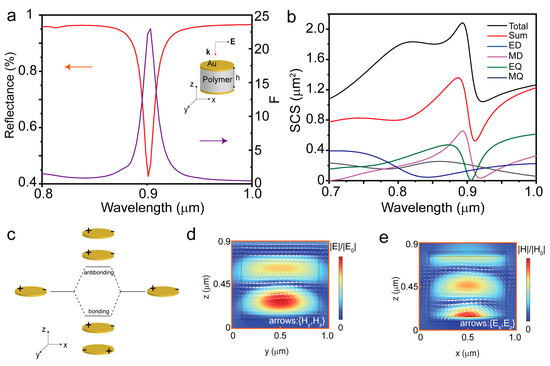
Figure 1.
(a) Reflection spectrum (orange line) of the array for the pillar radius of 400 nm and height of 50 nm (Au dressing)/620 nm (polymer pillar)/50 nm (Au substrate). The period of the array is 1.5 μm. The purple curve in panel a describes the normalized electric field intensity averaged within the polymer nanopillar (F). A schematic of the hybrid pillar is shown in the inset. (b) Spectra of the scattering cross-section, decomposed in magnetic dipole (MD), electric dipole (ED), magnetic quadrupole (MQ), and electric quadrupole (EQ) contributions. “Sum” is the sum of multipoles’ contributions, and “Total” is a scattering cross section obtained via direct numerical simulation. (c) Plasmon hybridization scheme of gold disk dimer. (d) Normalized electric field distributions for the single pillar in the y–z plane in the resonance state (λ = 900 nm). The arrows represent scattered in-plane magnetic field vector (Hy, Hz) on the y-z plane. (e) The color represents the modulus of the magnetic field normalized to the incident field |H/H0|. The arrows represent the in-plane electric field vector (Ex, Ez).
To figure out the origin of the large field enhancement at the dip wavelength of the reflection spectra, a multipolar decomposition was performed. The multipole expansion of the scattering cross section, calculated by applying the method in [45], is shown in Figure 1b. The total scattering cross-section has some deviation from the sum of all the multipoles’ contributions. When the size of the nanopillar (radius 150 nm, Tau = 50 nm, h = 80 nm) is small in Figure S2, this deviation can be negligible. Other higher-order multipoles’ contributions increase with an increase in size. These metal-based nanostructures can be understood as the plasmon hybridization model of the gold disk dimer [46]. It results in one antibonding mode with high energy and one bonding mode with lower energy, as shown in Figure 1c. The equivalent dipoles oscillate in phase and out of phase, respectively, resulting in a higher energy antibonding and a lower energy bonding resonance. Additionally, the out-of-phase oscillating for bonding resonance results in a circular loop-shaped electric field in the x–z plane in Figure 1e and mainly in the y-direction magnetic field in Figure 1d. The sandwiched structure serves as an FP cavity with high reflecting boundaries that are provided by a coated gold disk and film. The covered gold disk also serves as an antenna for boosting the resonance. The resonance condition will benefit more from its thickness, which is greater than 40 nm. In addition, almost-total covering (rau = 400 nm) will be better for this structure, as illustrated in Supplement S2. The optical response at the resonance is not a pure MD response because the lobes at the polymer/Au interface are caused by the induced currents in the metal. The light power is mainly confined in the polymer pillars by the strong enhanced resonance that will be beneficial for studying the efficient generation of the nonlinear harmonic in the low-index dielectric nanostructure.
3. Fabry–Pérot Resonance in the Hybrid Pillar
Next, we investigated the dependence of the total energy stored in the low-index pillar on the pillar height and incident wavelength at the fundamental frequency. The color map in Figure 2a displays the simulated results. As the pillar height becomes larger, the resonant wavelength is red-shifted. In the vertical direction, the sandwiched pillar is composed of two reflecting metal mirrors separated by a dielectric spacer that can support FP resonance under the condition h = mλ/2n, where h is the height of the cavity, n is the refractive index of the spacer, m is the integer, and λ is the effective wavelength. Considering that the wavelength is 900 nm and the refractive index of the polymer is 1.5, pillars with heights of ~0.6 μm, ~0.9 μm, ~1.2 μm, and ~1.5 μm would have the greatest ability to confine energy. The dashed white lines show the various orders of FP resonances where the height fits m/3 wavelengths inside the cavity created by the sandwiched structure. There is some deviation between the simulation and the formula, which may be caused by omitting the reflection phase shift term in the metasurface etalon multilayer system [47,48]. If the particle array is replaced by a simple film mirror, the resonance condition agrees well with the Fabry–Pérot resonance condition, as shown in Supplement S3.
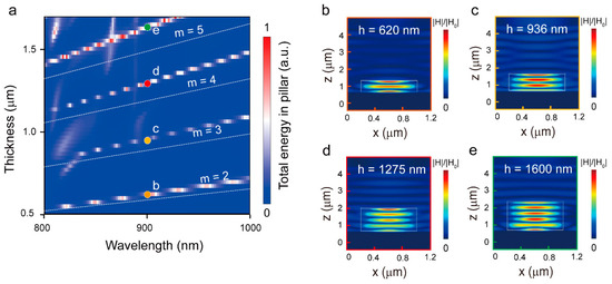
Figure 2.
(a) Simulation results for the total energy stored in the pillar for different values of pillar heights and incident wavelengths. The dashed white lines indicate the pillar heights necessary to fit m/3 wavelengths into the cavity formed by the sandwiched structure. (b–e) Magnetic field distributions for selected wavelengths (λ = 900 nm) and spacer heights 620 nm (b), 936 nm (c), 1275 nm (d), 1600 nm (e), indicated by the colored and labeled dots in (a).
To further analyze the orders of the FP resonance, we computed the magnetic field distribution in various pillar heights (Figure 2b–e) at the excitation wavelength of 900 nm. As expected, it displays the pattern of the MD resonant mode within the low-index dielectric. Orders 2–5 of the MD mode increase with the pillar height, which is a standing wave (FP resonance) that occurs within the cavity formed by the two metal mirrors. Additionally, we calculated the reflection spectra as a function of the antenna radius in Figure S3. The flexibility of this device is also demonstrated because by varying the pillar height (Figure 2a) or radius (Figure S4), the resonances shift. The large energy losses from the surrounding metal are effectively avoided by confining the energy of the fundamental frequency light inside the polymer pillar rather than the metal surface.
4. Third Harmonic Generation
In the nonlinear simulation, the electric polarization can be written as where χ(3)E2 ≪ χ(1) should guarantee the convergence of the FDTD model. The peak pump intensity of the incident pulse can be found from the relation [49]:
where ,,, and are the constants of the electric and magnetic permittivities of the medium and free space. Assuming , , and , the pump intensity is set to I0 = 0.01 GW/cm2, which corresponds to the incident electric field amplitude of 1 × 10⁷ V/m. Referring to the MD resonance wavelength obtained by linear scattering, the central wavelength of the source is selected at 900 nm with a full width at half maximum (FWHM) of 4.9 THz and a pulse duration of 90 fs. The source intensity of 0.01 GW/cm2 is a safe power density and will not harm the sample considering the damage threshold (2.7 TW/cm2 for a pulse duration of 90 fs) [50]. Polymers such as polydimethoxy-paraphenylenevinylene offer a reasonable third-order susceptibility [51] with χ(3) = 4 × 10⁻¹⁸ m2/V2. The optical properties of Au were taken from the JC model, and the third-order nonlinear susceptibility for gold [52] is approximately χ(3) = 7.56 × 10⁻¹⁹ m2/V2. A broadband monitor covering 0.2–1.2 μm was used to calculate the average output power by integrating the Poynting vector to obtain the average output power.
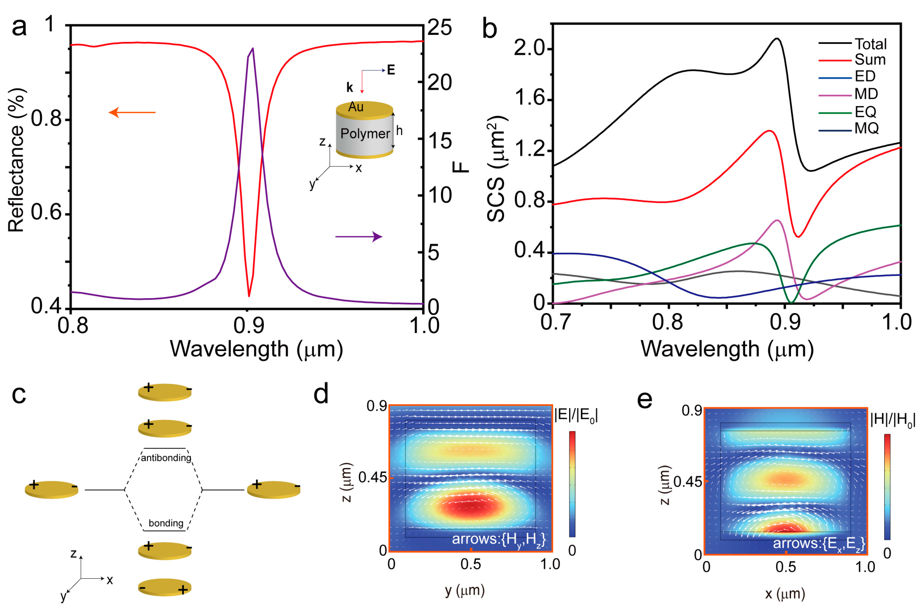
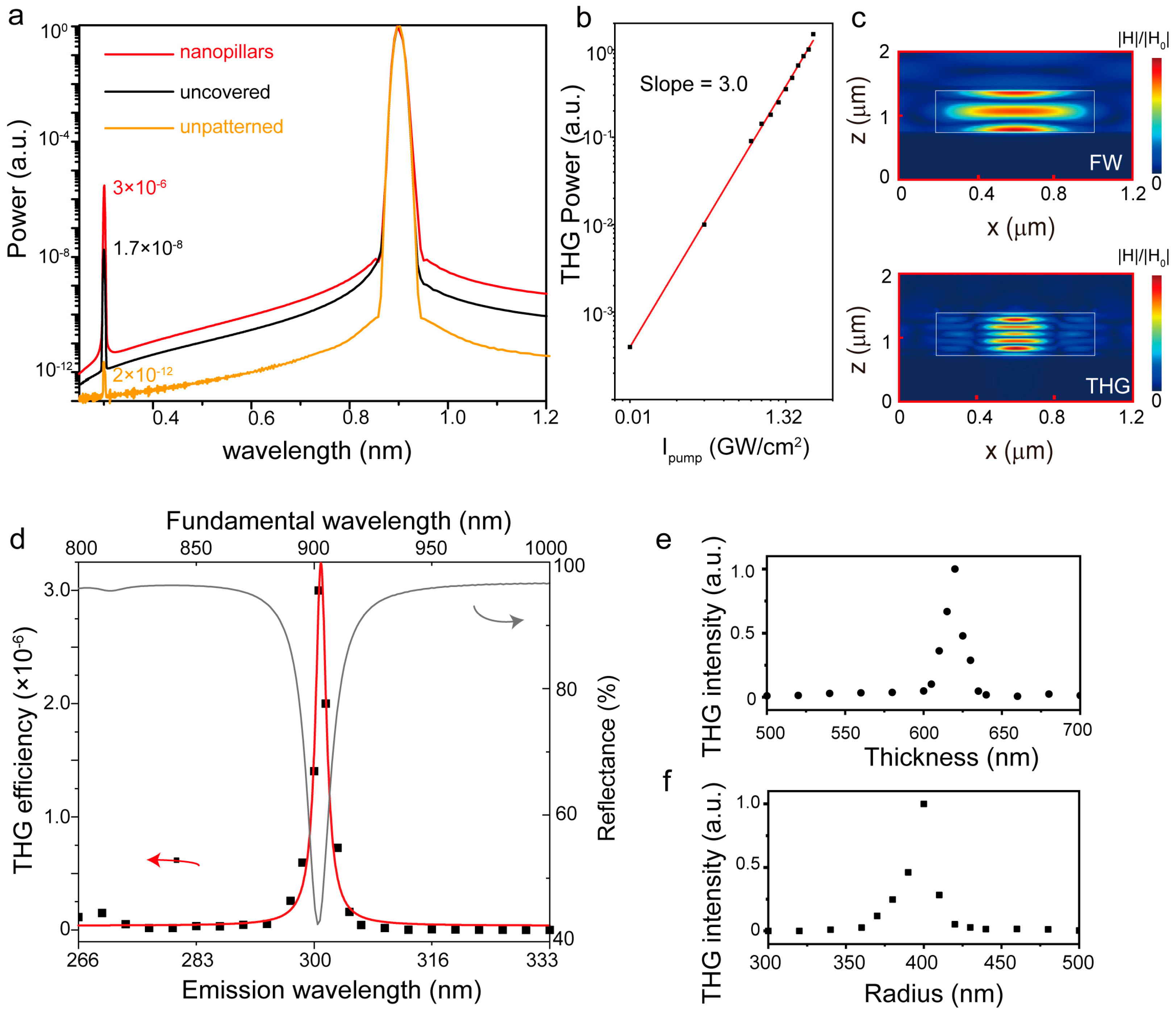
Figure 3a shows the far-field power spectrum from the sandwiched pillars with a radius of 400 nm and height of 620 nm, and there are two peaks corresponding to the pump (λ = 900 nm) and third harmonic (TH, λ = 300 nm), respectively. The THG conversion efficiency is estimated via the equation that follows:
PFF (PTH) is the power of the fundamental wavelength (third harmonic wavelength) by integrating the Poynting vector. The THG conversion efficiency obtained in Figure 3a reaches up to 3 × 10⁻⁶ at a pump power density of 0.01 GW/cm2, which is higher than the case of some other configurations, such as nanoantennas and metasurfaces (Table S1 in Supporting Information S5) This efficiency is about two orders of the pillars without Au dressing, coming from the strong resonance by utilizing the Au dressing. Compared with the unpatterned Au/polymer/Au film, the sandwiched pillar array has an efficient THG with an enhancement factor of 1.5 × 10⁶. The THG power of the nanopillars as a function of the pump power is plotted in Figure 3b. With the increased pump power, the THG power increases following the cubic law. Figure 3c shows the magnetic field at the fundamental and THG frequencies, and the field distributions are confined in nanopillars, which presents FP resonance characters with various orders. In Figure S5, it is evident that the optimal pulse duration lies at approximately 90 fs, leading to a THG conversion efficiency of up to 3 × 10⁻⁶. Beyond this duration, the THG conversion efficiency plateaus and gradually approaches saturation, which is a typical characteristic of cavity phenomena [53,54].
ηTH = PTH/PFF,

Figure 3.
(a) THG spectra from the patterned nanopillars (r = 400 nm, h = 620 nm), Au disk uncovered pillars, and the unpatterned Au/Polymer/Au film on the same substrate. (b) THG conversion efficiency as a function of pump light peak intensity. Fitting to these data produces a black line with a slope of 3.0 considering the expected cubic dependence. (c) Normalized field intensity distributions in the x–z plane at fundamental and TH wavelengths, respectively. The white solid lines depict the x–y cross-sections of the proposed polymer nanopillar. (d) THG enhancement as a function of the laser excitation wavelength with a height of 620 nm and a radius of 400 nm. The black dot is the simulation data, and the red line is the Lorentz fitting curve. The gray line is the fundamental reflection spectra. (e,f) THG enhancement as a function of the nanopillar height (e) and radius (f) at the fixed excitation wavelength λ = 900 nm.
The THG enhancement was then investigated using various excitation wavelengths (800–1000 nm), pillar heights (500–700 nm), and pillar radii (300–500 nm). Figure 3d shows the THG enhancement spectrum for the sandwiched pillar with a height of 620 nm and a radius of 400 nm. An enhancement peak of THG at around 300 nm is observed, corresponding to the valley of the reflection spectrum where the field enhancement inside the nanopillar is maximized (Figure 1a). The dependence of the maximum-intensity THG wavelength on the pillar height and radius is shown in Figure 3e,f. THG reaches its local maxima for the sandwiched pillar array at a height of 620 nm and a radius of 400 nm when the excitation wavelength is fixed at 900 nm. The sandwiched pillar structures serve as an effective example of the THG platform with multiple adjustable degrees of freedom.
5. Conclusions
In summary, we designed and proved in theory a low-index dielectric nanopillar array that is an efficient THG platform. The sandwiched metal dressing of polymer nanopillars helps support strong resonance that will improve the light power confinement in polymer and the interaction between the confined energy in the nanopillars and the far field. The resonance polymer nanopillars could achieve an enhancement of six orders of magnitude of the nonlinear harmonic conversion. The THG efficiency reaches up to 3 × 10⁻⁶ at a third harmonic wavelength of 300 nm at a pump power intensity of 0.01 GW/cm2. Additionally, we demonstrated that the THG platform has several degrees of freedom that may be adjusted, including the excitation wavelength and physical parameters (radius or height of pillars). Utilizing the sandwiched low-index dielectric nanopillar array to enhance the THG may provide a new idea for nonlinear optical conversion.
Supplementary Materials
The following supporting information can be downloaded at: https://www.mdpi.com/article/10.3390/photonics11020159/s1, S1: Influence from polymer with different refractive index; S2: Influence on the reflection spectra from the size of the covered Au disk; S3: The resonance condition for the Au/polymer/Au film; S4: Influence on the reflection spectra from polymer pillar radius; S5: Comparisons of the THG conversion efficiency; S6: THG conversion efficiency versus different pump light pulse durations.
Author Contributions
Conceptualization, X.H. and J.S.; methodology, J.S. and R.X.; software, R.X. and W.W.; validation, R.X., X.H. and J.S.; formal analysis, R.X. and J.S.; investigation, R.X. and J.S.; resources, R.X. and J.S.; data curation, R.X. and J.S.; writing—R.X.; writing—review and editing, R.X.; visualization, J.S.; supervision, X.H., L.Z. and J.S.; project administration, X.H., L.Z. and J.S.; funding acquisition, X.H., L.Z. and J.S. All authors have read and agreed to the published version of the manuscript.
Funding
This work was supported by the National Natural Science Foundation of China (Grant Nos. 12004223, 12004222, 12274270) and the Postdoctoral Science Foundation of China (Grant Nos. 2020M682223, 2020M682224).
Institutional Review Board Statement
Not applicable.
Informed Consent Statement
Not applicable.
Data Availability Statement
Data are contained within the article.
Conflicts of Interest
The authors declare no conflict of interest.
References
- Boyd, R.W. Nonlinear Optics, 3rd ed.; Elsevier: Burlington, VT, USA, 2008. [Google Scholar]
- Ma, R.-M.; Oulton, R.F. Applications of nanolasers. Nat. Nanotechnol. 2019, 14, 12–22. [Google Scholar] [CrossRef]
- Rodrigues, S.P.; Lan, S.; Kang, L.; Cui, Y.; Cai, W. Nonlinear Imaging and Spectroscopy of Chiral Metamaterials. Adv. Mater. 2014, 26, 6157–6162. [Google Scholar] [CrossRef]
- Kotov, N. The only way is up. Nat. Mater. 2011, 10, 903–904. [Google Scholar] [CrossRef]
- Tran, R.J.; Sly, K.L.; Conboy, J.C. Applications of Surface Second Harmonic Generation in Biological Sensing. Annu. Rev. Anal. Chem. 2017, 10, 387–414. [Google Scholar] [CrossRef]
- Menon, V.M.; Deych, L.I.; Lisyansky, A.A. Towards polaritonic logic circuits. Nat. Photonics 2010, 4, 345–346. [Google Scholar] [CrossRef]
- Li, G.; Zhang, S.; Zentgraf, T. Nonlinear photonic metasurfaces. Nat. Rev. Mater. 2017, 2, 17010. [Google Scholar] [CrossRef]
- Gramotnev, D.K.; Bozhevolnyi, S.I. Plasmonics beyond the diffraction limit. Nat. Photonics 2010, 4, 83–91. [Google Scholar] [CrossRef]
- Kuznetsov, A.I.; Miroshnichenko, A.E.; Brongersma, M.L.; Kivshar, Y.S.; Luk’yanchuk, B. Optically resonant dielectric nanostructures. Science 2016, 354, aag2472. [Google Scholar] [CrossRef] [PubMed]
- Xu, H. Nanophotonics: Manipulating Light with Plasmons; Pan Stanford: Singapore, 2017. [Google Scholar]
- Tseng, M.L.; Semmlinger, M.; Zhang, M.; Arndt, C.; Huang, T.T.; Yang, J.; Kuo, H.Y.; Su, V.C.; Chen, M.K.; Chu, C.H.; et al. Vacuum ultraviolet nonlinear metalens. Sci. Adv. 2022, 8, eabn5644. [Google Scholar] [CrossRef] [PubMed]
- Kauranen, M.; Zayats, A.V. Nonlinear plasmonics. Nat. Photonics 2012, 6, 737–748. [Google Scholar] [CrossRef]
- Li, Y.; Kang, M.; Shi, J.; Wu, K.; Zhang, S.; Xu, H. Transversely Divergent Second Harmonic Generation by Surface Plasmon Polaritons on Single Metallic Nanowires. Nano Lett. 2017, 17, 7803–7808. [Google Scholar] [CrossRef] [PubMed]
- Butet, J.; Brevet, P.-F.; Martin, O.J.F. Optical Second Harmonic Generation in Plasmonic Nanostructures: From Fundamental Principles to Advanced Applications. ACS Nano 2015, 9, 10545–10562. [Google Scholar] [CrossRef]
- Kim, S.; Jin, J.; Kim, Y.-J.; Park, I.-Y.; Kim, Y.; Kim, S.-W. High-harmonic generation by resonant plasmon field enhancement. Nature 2008, 453, 757–760. [Google Scholar] [CrossRef]
- Berthelot, J.; Bachelier, G.; Song, M.; Rai, P.; Colas des Francs, G.; Dereux, A.; Bouhelier, A. Silencing and enhancement of second-harmonic generation in optical gap antennas. Opt. Express 2012, 20, 10498–10508. [Google Scholar] [CrossRef] [PubMed]
- Zhang, X.; Cao, Q.-T.; Wang, Z.; Liu, Y.-X.; Qiu, C.-W.; Yang, L.; Gong, Q.; Xiao, Y.-F. Symmetry-breaking-induced nonlinear optics at a microcavity surface. Nat. Photonics 2018, 13, 21–24. [Google Scholar] [CrossRef]
- Michaeli, L.; Keren-Zur, S.; Avayu, O.; Suchowski, H.; Ellenbogen, T. Nonlinear surface lattice resonance in plasmonic nanoparticle arrays. Phys. Rev. Lett. 2017, 118, 243904. [Google Scholar] [CrossRef]
- Staude, I.; Pertsch, T.; Kivshar, Y.S. All-dielectric resonant meta-optics lightens up. ACS Photonics 2019, 6, 802–814. [Google Scholar] [CrossRef]
- Koshelev, K.; Kruk, S.; Melik-Gaykazyan, E.; Choi, J.-H.; Bogdanov, A.; Park, H.-G.; Kivshar, Y. Subwavelength dielectric resonators for nonlinear nanophotonics. Science 2020, 367, 288–292. [Google Scholar] [CrossRef]
- Shcherbakov, M.R.; Neshev, D.N.; Hopkins, B.; Shorokhov, A.S.; Staude, I.; Melik-Gaykazyan, E.V.; Decker, M.; Ezhov, A.A.; Miroshnichenko, A.E.; Brener, I. Enhanced third-harmonic generation in silicon nanoparticles driven by magnetic response. Nano Lett. 2014, 14, 6488–6492. [Google Scholar] [CrossRef]
- Shibanuma, T.; Grinblat, G.; Albella, P.; Maier, S.A. Efficient Third Harmonic Generation from Metal–Dielectric Hybrid Nanoantennas. Nano Lett. 2017, 17, 2647–2651. [Google Scholar] [CrossRef]
- Grinblat, G.; Li, Y.; Nielsen, M.P.; Oulton, R.F.; Maier, S.A. Enhanced Third Harmonic Generation in Single Germanium Nanodisks Excited at the Anapole Mode. Nano Lett. 2016, 16, 4635–4640. [Google Scholar] [CrossRef] [PubMed]
- Semmlinger, M.; Zhang, M.; Tseng, M.L.; Huang, T.-T.; Yang, J.; Tsai, D.P.; Nordlander, P.; Halas, N.J. Generating Third Harmonic Vacuum Ultraviolet Light with a TiO2 Metasurface. Nano Lett. 2019, 19, 8972–8978. [Google Scholar] [CrossRef] [PubMed]
- Sain, B.; Meier, C.; Zentgraf, T. Nonlinear optics in all-dielectric nanoantennas and metasurfaces: A review. Adv. Photonics 2019, 1, 024002. [Google Scholar] [CrossRef]
- Liu, Z.; Xu, Y.; Lin, Y.; Xiang, J.; Feng, T.; Cao, Q.; Li, J.; Lan, S.; Liu, J. High-Q quasibound states in the continuum for nonlinear metasurfaces. Phys. Rev. Lett. 2019, 123, 253901. [Google Scholar] [CrossRef] [PubMed]
- Koshelev, K.; Tang, Y.; Li, K.; Choi, D.-Y.; Li, G.; Kivshar, Y. Nonlinear Metasurfaces Governed by Bound States in the Continuum. ACS Photonics 2019, 6, 1639–1644. [Google Scholar] [CrossRef]
- Yang, G.; Dev, S.U.; Allen, M.S.; Allen, J.W.; Harutyunyan, H. Optical Bound States in the Continuum Enabled by Magnetic Resonances Coupled to a Mirror. Nano Lett. 2022, 22, 2001–2008. [Google Scholar] [CrossRef] [PubMed]
- Xu, L.; Rahmani, M.; Zangeneh Kamali, K.; Lamprianidis, A.; Ghirardini, L.; Sautter, J.; Camacho-Morales, R.; Chen, H.; Parry, M.; Staude, I.; et al. Boosting third-harmonic generation by a mirror-enhanced anapole resonator. Light Sci. Appl. 2018, 7, 44. [Google Scholar] [CrossRef]
- Shi, J.; Li, Y.; Kang, M.; He, X.; Halas, N.J.; Nordlander, P.; Zhang, S.; Xu, H. Efficient Second Harmonic Generation in a Hybrid Plasmonic Waveguide by Mode Interactions. Nano Lett. 2019, 19, 3838–3845. [Google Scholar] [CrossRef]
- Shi, J.; Guo, Q.; Shi, Z.; Zhang, S.; Xu, H. Nonlinear nanophotonics based on surface plasmon polaritons. Appl. Phys. Lett. 2021, 119, 130501. [Google Scholar] [CrossRef]
- Shi, J.; He, X.; Chen, W.; Li, Y.; Kang, M.; Cai, Y.; Xu, H. Remote Dual-Cavity Enhanced Second Harmonic Generation in a Hybrid Plasmonic Waveguide. Nano Lett. 2022, 22, 688–694. [Google Scholar] [CrossRef]
- Li, Y.; Zhang, G.; Tang, Y.; Zhang, X.; Cai, W.; Liu, Y.; Cao, T.; Li, G. Third harmonic generation from the gold/amorphous silicon hybrid metasurface. Nanophotonics 2022, 11, 2245–2251. [Google Scholar] [CrossRef]
- Slowing, I.I.; Trewyn, B.G.; Giri, S.; Lin, V.S.Y. Mesoporous Silica Nanoparticles for Drug Delivery and Biosensing Applications. Adv. Funct. Mater. 2007, 17, 1225–1236. [Google Scholar] [CrossRef]
- Liong, M.; Lu, J.; Kovochich, M.; Xia, T.; Ruehm, S.G.; Nel, A.E.; Tamanoi, F.; Zink, J.I. Multifunctional Inorganic Nanoparticles for Imaging, Targeting, and Drug Delivery. ACS Nano 2008, 2, 889–896. [Google Scholar] [CrossRef]
- De, M.; Ghosh, P.S.; Rotello, V.M. Applications of Nanoparticles in Biology. Adv. Mater. 2008, 20, 4225–4241. [Google Scholar] [CrossRef]
- Yu, T.; Malugin, A.; Ghandehari, H. Impact of Silica Nanoparticle Design on Cellular Toxicity and Hemolytic Activity. ACS Nano 2011, 5, 5717–5728. [Google Scholar] [CrossRef]
- Si, Y.; Guo, Z. Superhydrophobic nanocoatings: From materials to fabrications and to applications. Nanoscale 2015, 7, 5922–5946. [Google Scholar] [CrossRef] [PubMed]
- Manca, M.; Cannavale, A.; De Marco, L.; Aricò, A.S.; Cingolani, R.; Gigli, G. Durable Superhydrophobic and Antireflective Surfaces by Trimethylsilanized Silica Nanoparticles-Based Sol−Gel Processing. Langmuir 2009, 25, 6357–6362. [Google Scholar] [CrossRef] [PubMed]
- Zhou, J.; Panday, A.; Xu, Y.; Chen, X.; Chen, L.; Ji, C.; Guo, L.J. Visualizing Mie Resonances in Low-Index Dielectric Nanoparticles. Phys. Rev. Lett. 2018, 120, 253902. [Google Scholar] [CrossRef] [PubMed]
- Lu, Y.; Lam, S.H.; Lu, W.; Shao, L.; Chow, T.H.; Wang, J. All-State Switching of the Mie Resonance of Conductive Polyaniline Nanospheres. Nano Lett. 2022, 22, 1406–1414. [Google Scholar] [CrossRef] [PubMed]
- Ao, X.; Wang, D.; Odom, T.W. Enhanced Fields in Mirror-Backed Low-Index Dielectric Structures. ACS Photonics 2019, 6, 2612–2617. [Google Scholar] [CrossRef]
- Chen, S.; Li, K.F.; Li, G.; Cheah, K.W.; Zhang, S. Gigantic electric-field-induced second harmonic generation from an organic conjugated polymer enhanced by a band-edge effect. Light Sci. Appl. 2019, 8, 17. [Google Scholar] [CrossRef]
- Albrecht, G.; Hentschel, M.; Kaiser, S.; Giessen, H. Hybrid organic-plasmonic nanoantennas with enhanced third-harmonic generation. ACS Omega 2017, 2, 2577–2582. [Google Scholar] [CrossRef]
- Evlyukhin, A.B.; Fischer, T.; Reinhardt, C.; Chichkov, B.N. Optical theorem and multipole scattering of light by arbitrarily shaped nanoparticles. Phys. Rev. B 2016, 94, 205434. [Google Scholar] [CrossRef]
- Nordlander, P.; Oubre, C.; Prodan, E.; Li, K.; Stockman, M.I. Plasmon Hybridization in Nanoparticle Dimers. Nano Lett. 2004, 4, 899–903. [Google Scholar] [CrossRef]
- Kwadrin, A.; Osorio, C.I.; Koenderink, A.F. Backaction in metasurface etalons. Phys. Rev. B 2016, 93, 104301. [Google Scholar] [CrossRef]
- Berkhout, A.; Koenderink, A.F. Perfect absorption and phase singularities in plasmon antenna array etalons. ACS Photonics 2019, 6, 2917–2925. [Google Scholar] [CrossRef]
- Vaičaitis, V.; Paulikas, Š. Conical four-wave mixing in sodium vapour excited by femtosecond laser pulses. Appl. Phys. B 2007, 89, 267–273. [Google Scholar] [CrossRef]
- Summers, A.M.; Ramm, A.S.; Paneru, G.; Kling, M.F.; Flanders, B.N.; Trallero-Herrero, C.A. Optical damage threshold of Au nanowires in strong femtosecond laser fields. Opt. Express 2014, 22, 4235–4246. [Google Scholar] [CrossRef] [PubMed]
- Nie, W. Optical nonlinearity: Phenomena, applications, and materials. Adv. Mater. 1993, 5, 520–545. [Google Scholar] [CrossRef]
- Li, K.; Li, X.; Yuan Lei, D.; Wu, S.; Zhan, Y. Plasmon gap mode-assisted third-harmonic generation from metal film-coupled nanowires. Appl. Phys. Lett. 2014, 104, 261105. [Google Scholar] [CrossRef]
- Vincenti, M.A.; de Ceglia, D.; Roppo, V.; Scalora, M. Harmonic generation in metallic, GaAs-filled nanocavities in the enhanced transmission regime at visible and UV wavelengths. Opt. Express 2011, 19, 2064–2078. [Google Scholar] [CrossRef] [PubMed]
- Li, Y.; Huang, Z.; Sui, Z.; Chen, H.; Zhang, X.; Huang, W.; Guan, H.; Qiu, W.; Dong, J.; Zhu, W.; et al. Optical anapole mode in nanostructured lithium niobate for enhancing second harmonic generation. Nanophotonics 2020, 9, 3575–3585. [Google Scholar] [CrossRef]

Disclaimer/Publisher’s Note: The statements, opinions and data contained in all publications are solely those of the individual author(s) and contributor(s) and not of MDPI and/or the editor(s). MDPI and/or the editor(s) disclaim responsibility for any injury to people or property resulting from any ideas, methods, instructions or products referred to in the content. |
© 2024 by the authors. Licensee MDPI, Basel, Switzerland. This article is an open access article distributed under the terms and conditions of the Creative Commons Attribution (CC BY) license (https://creativecommons.org/licenses/by/4.0/).