1. Introduction
New techniques for short-reach optical transmission applications such as optical access networks, data centers, and super-computer interconnects are being used to break the current bandwidth bottleneck [
1]. In addition to wavelength-division multiplexing, mode-division multiplexing (MDM) based on few-mode fiber (FMF) is a promising technique that utilizes linearly polarized (LP) modes as spatial transmission channels [
2,
3]. Since modal crosstalk is not suppressed in strongly coupled MDM transmission systems, coherent detection and multiple-input multiple-output (MIMO) digital signal processing (DSP) are always required at the receiver [
4,
5]. However, their huge computational complexity is not suitable for short-reach transmission scenarios, where simple and low-cost intensity modulation and direct detection (IM/DD) approaches without DSP are preferred. Consequently, weakly coupled MDM transmission techniques have been proposed, in which the modal crosstalk is suppressed as much as possible for the overall transmission system including the fibers, optical components, and the coupling between them [
6,
7]. In weakly coupled MDM systems, high compatibility with conventional IM/DD optical transceivers is expected.
Two kinds of modal crosstalk need to be handled to achieve IM/DD MDM transmission in circular-core FMFs. The first one is the inter-LP-mode crosstalk, which is inversely related to the modal effective refractive index difference (∆
neff) between two LP modes. The overall modal-crosstalk performance of a weakly coupled MDM system is mainly determined by the minimum |∆
neff| (min|∆
neff|) among all the LP modes. As is known, the min|∆
neff| could be enlarged by increasing the core–cladding index difference or decreasing the core radius. These changes will inevitably yield high fiber nonlinearities, large attenuation, and severe modal birefringence [
8]. A more effective approach is adopting perturbed ring areas in the fiber core to adjust the
neff of all LP modes to approach equal spacing as much as possible [
9,
10]. The second modal crosstalk is the intra-LP-mode crosstalk between each pair of degenerate modes (LP
lma and LP
lmb,
l ≥ 1). Because of random perturbations and imperfect fiber fabrications, the modal field of the degenerate modes will rotate randomly along the FMF propagation [
11]. Since the two degenerate modes cannot be distinguished at the end of the FMF, 4 × 4 MIMO DSP is needed to handle the mode degeneracy and polarization [
12,
13]. IM/DD MDM transmissions less than 1 km can utilize elliptical-core FMFs to break the modal degeneracy [
14]. However, non-circular-core FMFs may meet problems when expending to longer transmission distances and more modes. Therefore, circular-core FMFs are required in IM/DD MDM transmission longer than 1 km with more than one pair of degenerate modes. In order to avoid any DSP including the 4 × 4 MIMO processing, it is necessary to utilize the two degenerate modes as a whole LP mode. Consequently, the whole system is actually an LP-mode MDM transmission link. However, regular mode demultiplexers for non-circular-symmetric LP modes can only convert the mode with a certain spatial orientation to the fundamental mode of a single-mode fiber (SMF) [
15]. Optical powers in modes with other spatial orientations will be abandoned at the receiver, which will induce severe power fluctuation. At a given coordinate, non-circular-symmetric LP
lm modes with any angular rotation can be regarded as the linear combination of the degenerate LP
lma and LP
lmb modes [
16]. Therefore, optical powers in both degenerate modes should be collected to ensure a stable reception. Several reception schemes for degenerate modes have been proposed so far. For instance, a photonic lantern is employed to demultiplex signals in two degenerate modes into two SMFs, respectively. Then, the optical powers in the two SMFs are combined and converted by another photonic lantern to an FMF output [
17]. Multi-plane light conversion is also used to deal with the mode degeneracy by converting each pair of higher-order degenerate modes to a different lower-order mode and coupling the optical powers to a multimode fiber pigtail [
18,
19,
20]. Another possible approach is based on angularly multiplexed volume holograms [
21,
22]. However, the modal selectivity and demultiplexing efficiency of this scheme need to be improved in order to achieve DSP-free IM/DD MDM transmission.
In this paper, we review our recent studies on degenerate-mode-reception schemes for DSP-free IM/DD LP-mode MDM transmission. A low-modal-crosstalk orthogonal combined reception scheme for degenerate mode demultiplexing is firstly investigated [
23]. Then, a degenerate-mode-selective coupler (DMSC) is proposed, which could simplify the demultiplexer [
24]. The two schemes are realized by tapering and side-polishing techniques. The fabricated demultiplexers are characterized and the results are discussed. Compared to other degenerate-mode-reception schemes, the two approaches proposed in this paper are based on all-fiber modal couplers, which have the advantages of insertion loss, modal selectivity, and fabrication complexity.
2. Demultiplexers Based on All-Fiber Mode-Selective Couplers
In a polar coordinate, transverse field components of the LP
lm mode of a FMF are as follows:
where
Al is the amplitude of the transverse field components,
Jl is the Bessel function of the first kind,
Kl is the modified Bessel function of the second kind, a is the radius of the core,
l is the azimuthal mode number, and
u and
w are the transverse propagation constants in the core and cladding, respectively.
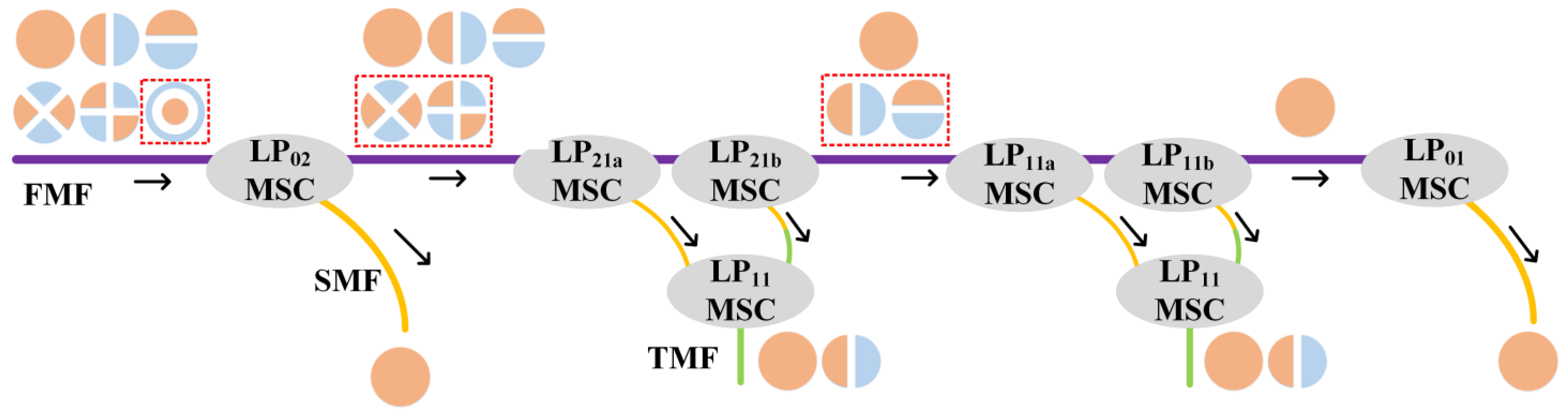
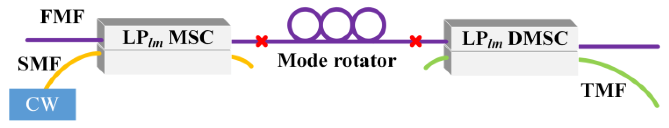
The structure of the proposed all-fiber mode demultiplexers for LP-mode MDM transmission is shown in
Figure 1. Regular mode-selective couplers (MSCs) are adopted for the reception of circular–symmetric LP modes. Since a single MSC can only demultiplex degenerate LP modes with one spatial orientation, two orthogonally cascaded MSCs for a pair of degenerate LP modes are utilized to demultiplex the two degenerate modes into the LP
01 mode of two SMFs. However, utilizing a 3 dB optical coupler to combine the two signals into an SMF will induce additional loss. Therefore, an LP
11 MSC is followed as a combiner to multiplex the optical power in two SMFs into mutually orthogonal LP
01 and LP
11 modes of a two-mode fiber (TMF) to achieve degenerate-mode reception. The outputs of the mode demultiplexer are commonly followed by photo detectors (PDs) for detection. The PDs could be spatially coupled or have a few-mode/multimode pigtail fiber to detect the optical power in LP
01 and LP
11 modes. It should be noted that the two branches before combining should have identical length to avoid temporal broadening of signal.
The 4-LP mode demultiplexer consisting of four kinds of regular MSCs and a combiner LP
11 MSC are fabricated based on taper and polish method [
25]. Regular MSCs are fabricated utilizing 4-LP-mode FMFs and SMFs, while the combiner MSCs are fabricated using TMFs and SMFs.
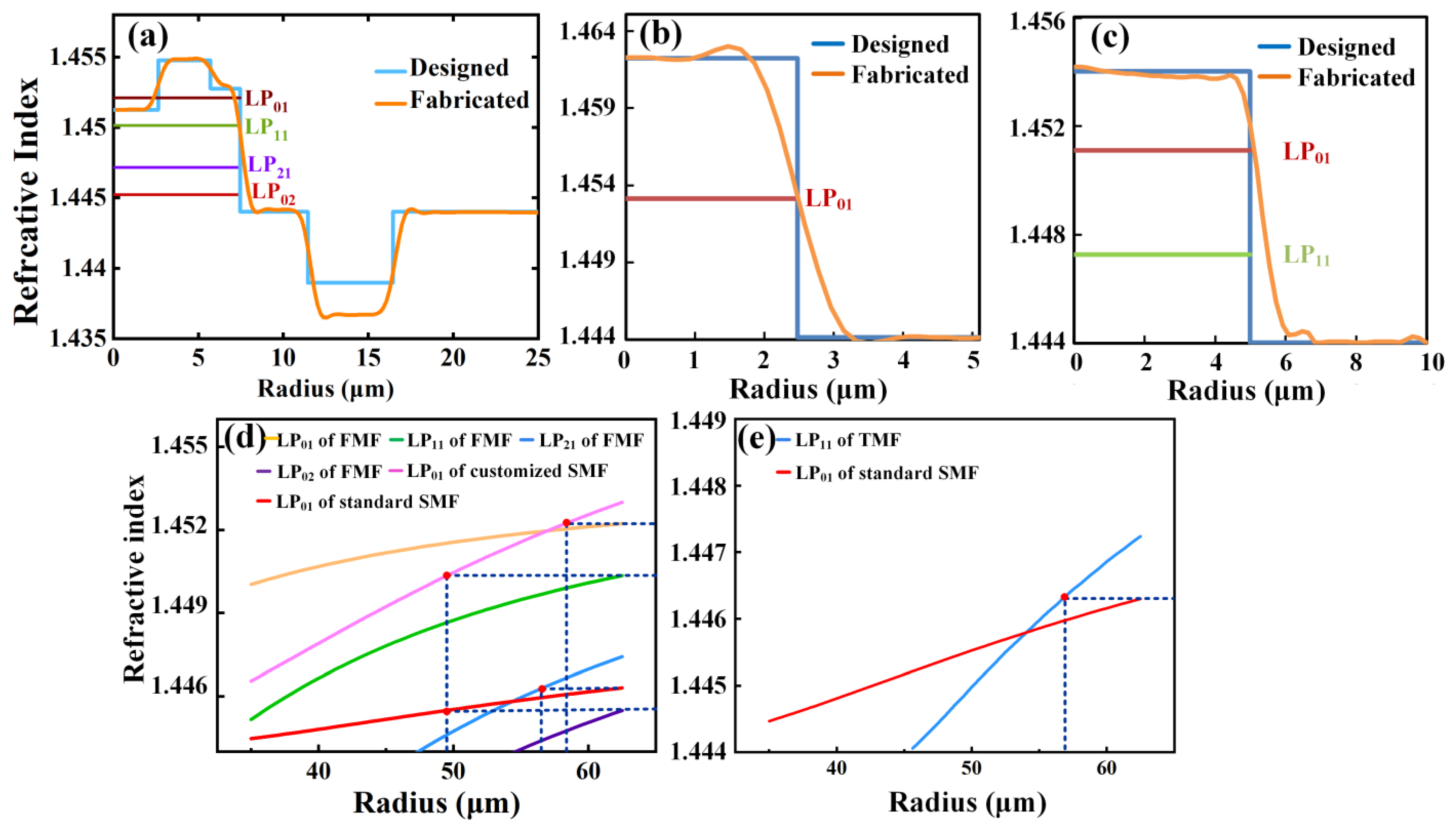
Figure 2a depicts the refractive index profiles of the 4-LP-mode fiber. It supports 4 LP modes with a normalized frequency
V of 4.8 and a refractive index difference (Δ
n) between the fiber core and cladding of 0.6% at 1550 nm. Three perturbed ring areas are applied to enlarge the mode spacing and a min|Δ
neff| up to 1.89 × 10
−3 is achieved. A fluorine-doped trench is applied in the cladding to reduce the attenuation and bending loss. An SMF with Δ
n of 1.23% at 1550 nm is customized for the fabrication of LP
01 and LP
11 MSCs. It has a step index profile which is depicted in
Figure 2b. The core and cladding radii of the SMF are 2.48 and 62.5 μm, respectively. A standard SMF is adopted for the fabrication of LP
21 and LP
02 MSCs. For the combiner LP
11 MSC, a TMF with core/cladding radius of 5/62.5 μm and Δ
n of 0.688% at 1550 nm is adopted, whose index profiles are depicted in
Figure 2c.
In order to be phase-matched, some fibers should be tapered on a biconical taper station to decrease the
neff of the desired modes.
Figure 2d shows the
neff of all the LP modes in the standard SMF, customized SMF, and FMF as functions of the tapered radii. The intersections of two dotted lines illustrate the desired radii for the fabrication of different MSCs. The radius of customized SMF should be tapered to 58.5 and 49.2 μm, respectively, for the LP
01 and LP
11 MSCs, while the radius of the FMF is supposed to be tapered to 57 μm for the LP
21 MSCs. For the LP
02 MSC, the radius of the standard SMF should be tapered to 49 μm. After the tapering process, the FMFs and SMFs are, respectively, inserted into a quartz substrate and polished on a grinding platform. The two coupler halves are matched together to form the all-fiber MSC. The LP
11 MSCs acting as combiners are fabricated similarly. The
neff of the LP
11 mode in the TMF and the LP
01 mode in the standard SMF versus the taper radius are shown in
Figure 2e. The radius of the TMF was tapered to 57 μm for the MSCs, which are used as power combiners.
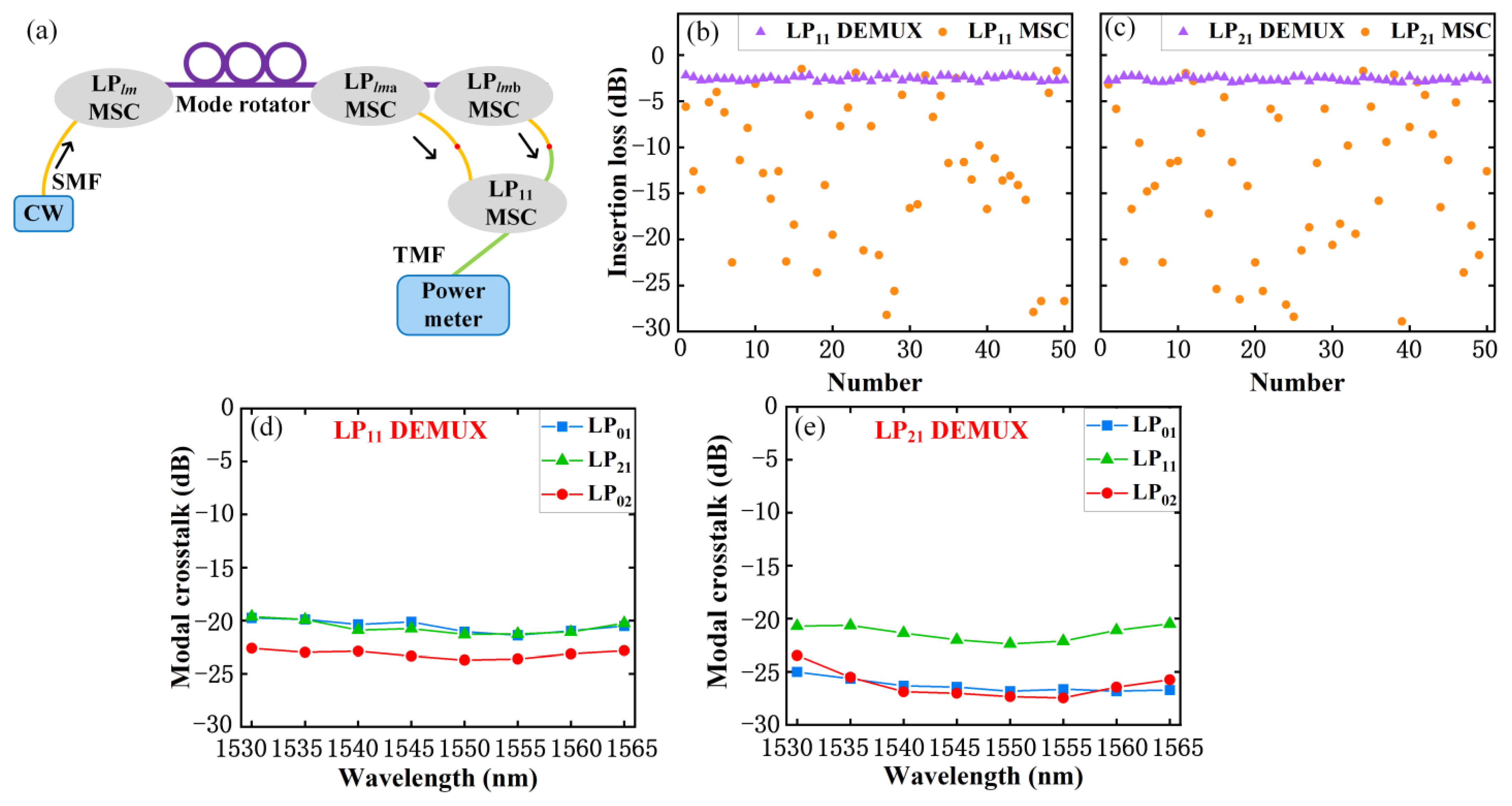
The demultiplexing stability for LP
11 and LP
21 modes are investigated with the setup shown in
Figure 3a. The two LP
11 (LP
21) MSCs are cascaded by fusion splice and the orthogonality is achieved by adjusting the FMF between them. The combiner LP
11 MSC is also connected by fusion splice. The lengths of the two input pigtail fibers of the combiner LP
11 MSC are precisely controlled to ensure the two branches before the combiner are identical. Optical power is launched through an LP
11 (LP
21) MSC stimulated by a tunable continuous-wave (CW) laser. The mode rotator is inserted before the demultiplexer to rotate the lobe orientations as well as polarization of input modes, and the output power of the demultiplexer is measured by a power meter. The mode rotator is a three-paddle polarization controller wound by the FMF. The insertion loss (IL) and power stability of regular MSCs for mode demultiplexing are also measured for comparison. IL is measured 50 times by randomly adjusting the mode rotator and the results are shown in
Figure 3b,c. Only slight power fluctuation is observed for the proposed degenerate mode demultiplexers, while the power fluctuation for regular MSCs is quite large. The modal selectivity is evaluated by exciting each of the other three LP modes one by one. The wavelength of probe signal is tuned over the C-band and the results are shown in
Figure 3d,e. The modal crosstalk of all modes is lower than −21 dB at 1550 nm and lower than −19.6 dB over the C-band.
3. Degenerate-Mode-Selective Fiber Couplers for Degenerate-Mode Reception
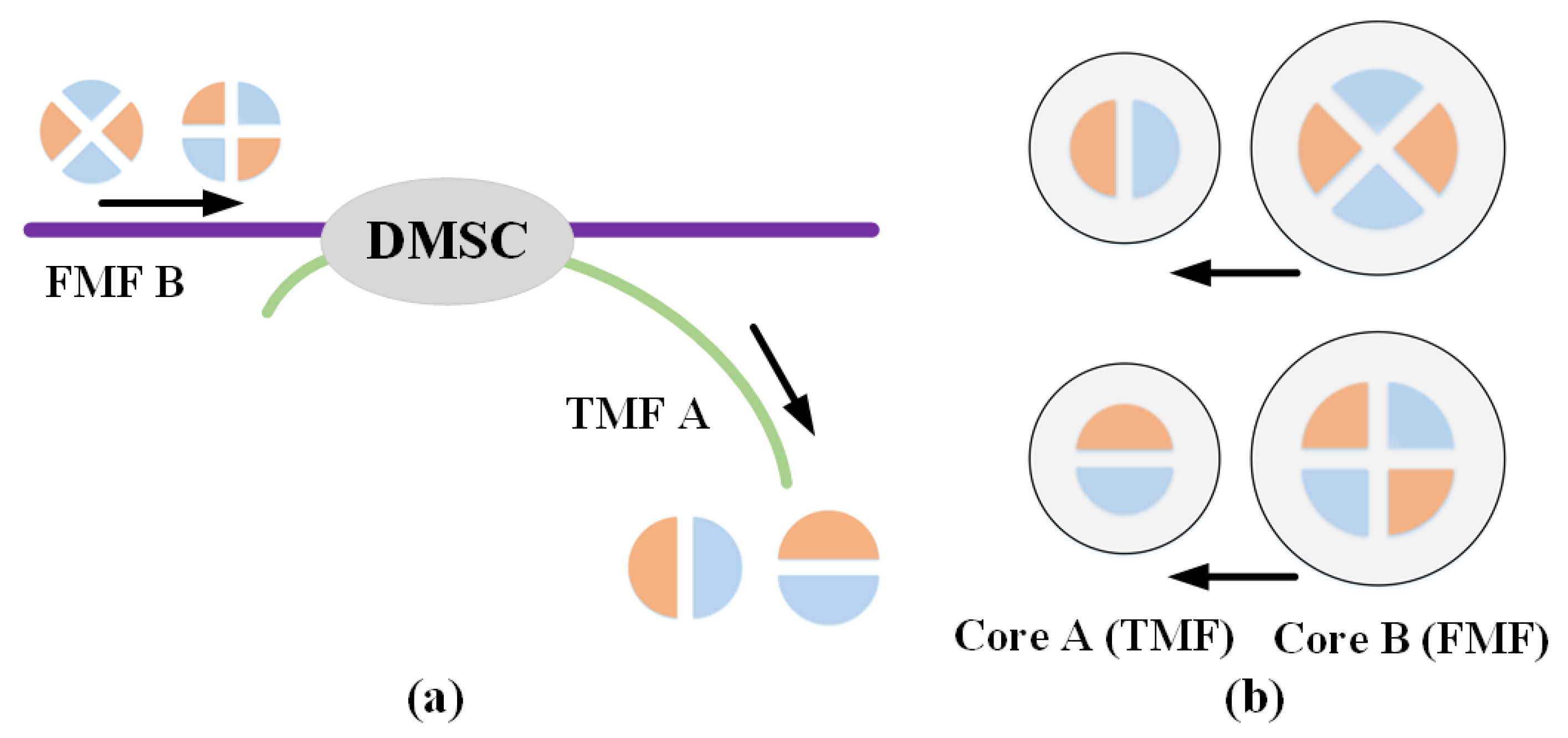
The scheme based on all MSCs requires a two-step process of converting and combining which will inevitably introduce external IL. In addition, the length of the optical paths of the two branches should be strictly identical during the combining so as to avoid temporal delay. In order to solve these problems, a degenerate-mode-selective fiber coupler is proposed for the reception of the degenerate modes. From the perspective of dimensions, if the optical powers in both degenerate modes are converted by the DMSC into a single output fiber, the fiber should sustain at least two spatial degrees of freedom. Consequently, the output fiber has to be an FMF. A straightforward approach is to make the output fiber the same as the original FMF. Then, the DMSC will be a symmetric two-core few-mode fiber coupler. However, this is not the best solution. On one hand, the modal selectivity of the DMSC will vanish by using two identical fibers. This is because the phase-matching conditions are always satisfied between two identical FMFs and the DMSC will inevitably extract energy from unwanted modes. On the other hand, the output fiber of the DMSC is commonly coupled to a PD for optoelectronic conversion. Fibers with smaller core diameters are easier to couple to high-speed PDs with smaller effective areas. Because all degenerate modes only have the same two-fold degeneracy, utilizing a TMF as the output fiber will provide enough dimensionalities and be very useful. Consequently, the DMSC is an asymmetric few-mode fiber coupler which consists of an input FMF and an output TMF, as shown in
Figure 4a. In addition, since the LP
lma and LP
lmb modes can only couple to the same kind of degenerate modes, the proposed LP
lm DMSC functions as two independent few-mode couplers. As can be seen in
Figure 4b, the LP
lma mode of the core B couples to the LP
11a mode of core A, and the LP
lmb mode of the core B couples to the LP
11b mode of the core A.
The necessary conditions of the DMSC are investigated. Assuming that the FMF initially carries unit optical power in LP
lma mode and no power was exited in the TMF, the power transfers for the FMF and TMF are as follows:
where
Plma(
z) is the normalized optical power carried by LP
lma mode in the FMF (as functions of the axial distance
z along the coupler);
P11a(
z) is the normalized optical power carried by LP
11a mode in the TMF.
Fa is the normalized peak power and
Ca is the power coupling coefficient. The power transfers for the LP
lmb and LP
11b modes are similarly. Provided the LP
lm mode of the FMF is phase-matched to the LP
11 mode of TMF, the power in the LP
lma and LP
lmb modes of FMF B can completely couple to the LP
11a and LP
11b modes of TMF A, respectively, when
are simultaneously satisfied (where
κa is the coupling coefficient between the LP
lma mode of the FMF B and the LP
11a mode of the TMF A).
κb is the coupling coefficient between the LP
lmb mode of the FMF B and the LP
11b mode of the TMF A.
L is the coupling length,
Equations (1) and (2) can be satisfied by tuning the core-to-core distance
d and the coupling length
L.
In this paper, the LP
11, LP
21 and LP
31 DMSCs are firstly designed using the beam propagation method. We adopt an FMF with a min|Δ
neff| up to 1.49 × 10
−3 among all LP modes [
26]. The radii of the core and cladding of the FMF are 8.25 and 62.5 μm, respectively. The Δ
n of the FMF is 0.748%. The radii of the core and cladding of the TMF are 5 and 62.5 μm, respectively. The Δ
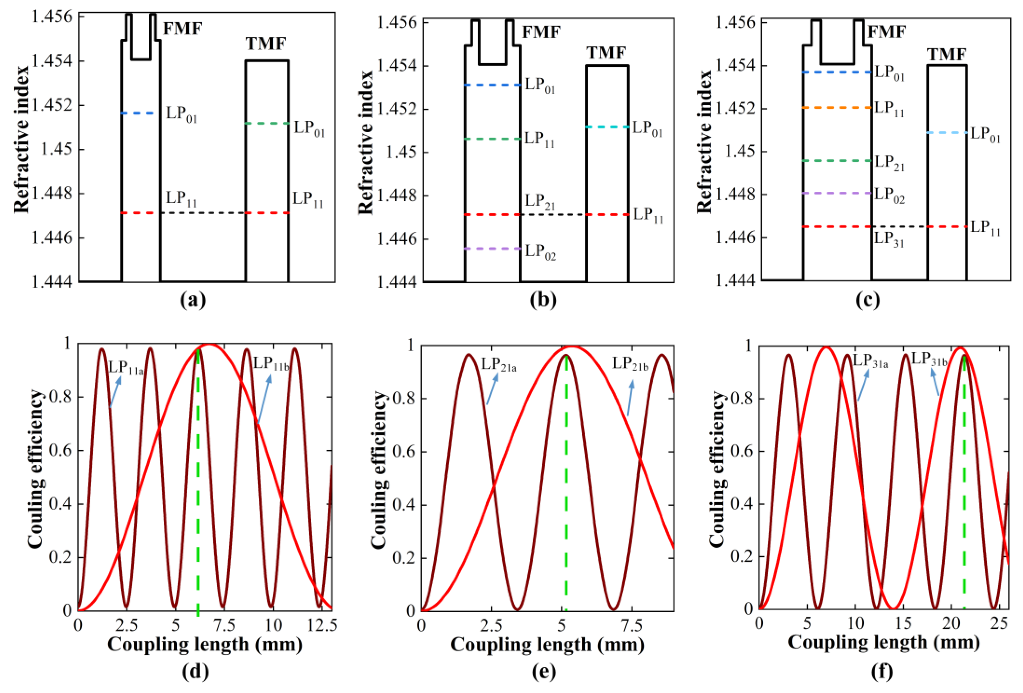
n of the TMF is 0.688%. In order to achieve the functions of DMSC, the phase-matching condition should be satisfied by tapering the FMF or the TMF. For the LP
11 and LP
21 DMSCs, the radii of the FMF should be tapered to 34.3 and 50.2 μm, respectively. For the LP
31 DMSC, the radius of the TMF needs to be tapered to 58.5 μm. The index profiles of the two fibers of the LP
11, LP
21, and LP
31 DMSCs after tapering are illustrated in
Figure 5a–c, respectively. The coupling length
L and the core-to-core distances
d are designed by parameter sweeping. The coupling efficiencies versus
L for both degenerate modes are calculated for each value of
d. After the optimization, the core-to-core distances
d are set to 12.53, 14.42 and 16.63 μm for the LP
11, LP
21, and LP
31 DMSCs, respectively. The coupling lengths
L are set to 6.17, 5.18 and 21.33 mm for the LP
11, LP
21, and LP
31 DMSCs, respectively. In this case, the coupling efficiencies of both degenerate modes will reach the maximum simultaneously, as depicted in
Figure 5d–f.
Similar to the regular all-fiber MSCs, the designed LP
11, LP
21 and LP
31 DMSCs are also fabricated utilizing the taper and polish method. We measured the power stability and IL of the three DMSCs using the setup shown in
Figure 6. The optical power in the target LP mode is generated by a regular MSC. A mode rotator is employed to adjust the orientations of the modal field before the DMSC. The demultiplexing performances of the LP
11, LP
21 and LP
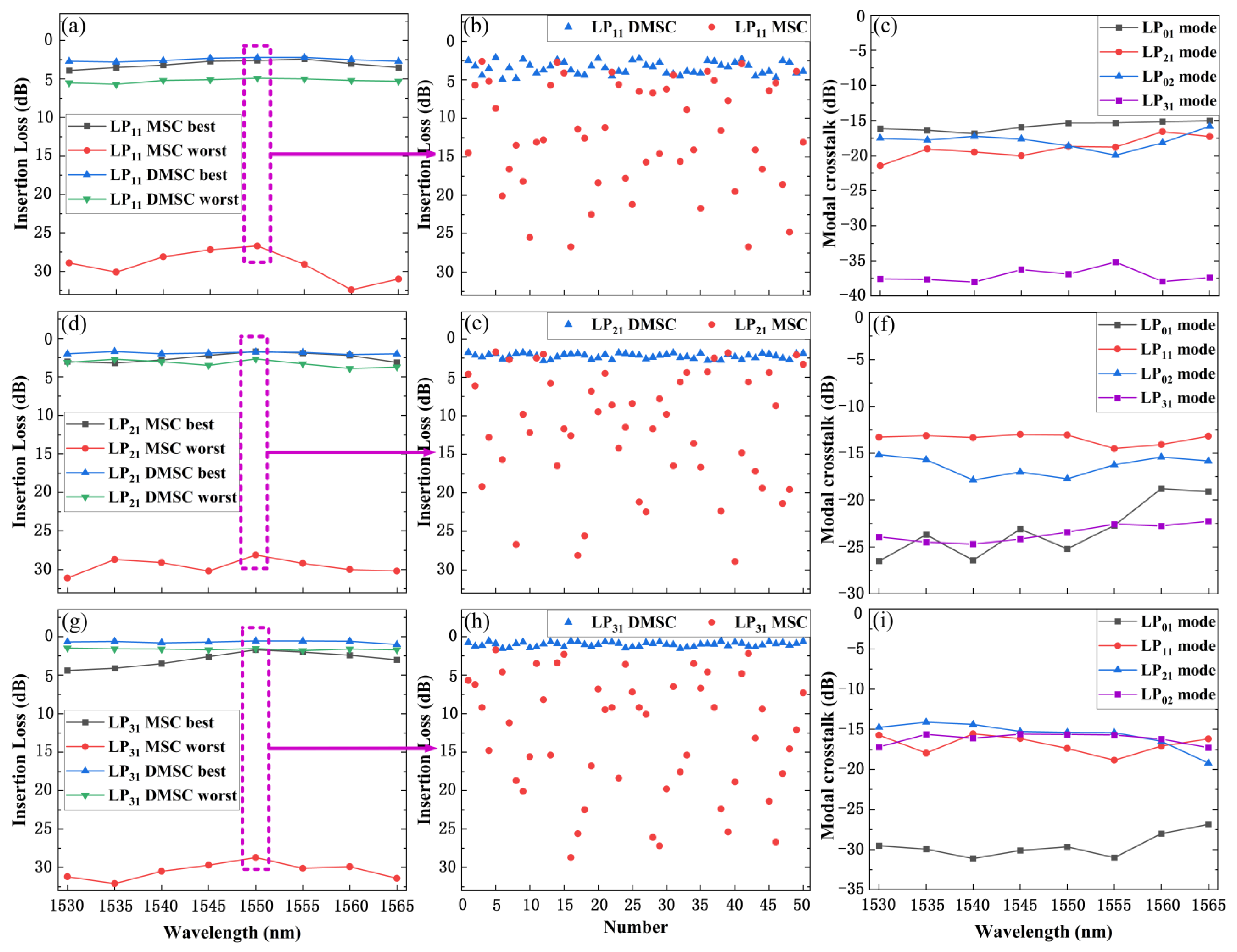
31 MSCs are also characterized as a contrast. The wavelength of the light source over the C band is tuned and the output optical power of the TMF of the DMSC (the SMF of the MSC) is recorded. As can be seen, the best and worst insertion loss for the LP
11, LP
21 and LP
31 DMSCs(MSCs) after a 50 random adjustments of the modal field over the C band are shown in
Figure 7a,d,g. The results of the insertion loss measurements at 1550 nm are illustrated in
Figure 7b,e,h, respectively. It can be seen that the variation in the IL of the LP
11, LP
21 and LP
31 MSCs is quite severe, and only minor variation happens in the proposed DMSCs. The fluctuations of the optical power are all lager than 20 dB for three regular MSCs over the C band. Meanwhile, the average variations are 2.7, 1.9 and 3.3 dB for the LP
11, LP
21 and LP
31 DMSCs, respectively.
The modal crosstalk performance of the DMSCs is characterized by inputting the optical power of the other three modes, respectively. The experimental results for the LP
11, LP
21, and LP
31 DMSCs are shown in
Figure 7c,f,i. Over the C-band, the largest modal crosstalk for the LP
11 DMSC is −15.7 dB, while it is −13.4 and −15.4 dB for the LP
21 and LP
31 DMSCs, respectively. The modal crosstalk comes from phase mismatch during the fabrication. Moreover, other LP modes may slightly couple to the LP
01 mode of the output TMF. The modal selectivity performance can be optimized during the manufacturing process by more precisely phase-matching the conditions.

