Article

Analysis of Interference Effect in Double Optomechanically Induced Transparency System

School of Physics and Electronics, Shandong Normal University, Jinan 250014, China
*
Author to whom correspondence should be addressed.
Photonics 2024, 11(4), 289; https://doi.org/10.3390/photonics11040289
Submission received: 27 February 2024 / Revised: 15 March 2024 / Accepted: 21 March 2024 / Published: 22 March 2024
(This article belongs to the Section Quantum Photonics and Technologies)

Abstract

:
We propose a scheme to investigate the interference properties of a double optomechanically induced transparency system, which involves two charged nanomechanical resonators, coupled via Coulomb interaction. The results show that the opening of transparency windows is caused by a destructive interference effect only in the weak optical coupling region. For strong optical coupling, normal mode splitting dominates the transparency phenomenon. In the intermediate region, both destructive interference and normal mode splitting contribute to the transparency windows. When the Coulomb coupling is much weaker than the optical coupling, the Coulomb interaction strength linearly determines the distance between the two transparency windows, and has nearly no influence on the destructive interference effect. Otherwise, the system will work in a nonlinear region.

1. Introduction

Optomechanically induced transparency (OMIT) has recently attracted significant attention as a phenomenon of interference resulting from the resonant interaction between the mechanical vibrations and the optical fields in the optomechanical systems [1,2,3,4,5]. This effect leads to a substantial suppression of probe field absorption in the cavity. Such phenomenon is of interest in fundamental physics research because it involves the marvelous interaction between photons and phonons. Furthermore, in practical applications [6,7,8], it also provides a means of controlling the interaction between light and mechanical vibrations, such as ultra-fast and ultra-low light propagation [9,10,11], quantum routing [12,13,14], precision measurements [15,16,17], optical storage [18,19], and so on.
Double OMIT, which involves two nanomechanical resonators interacting with a single optical cavity, produces complex interference patterns that can significantly affect the transmission of light through the cavity [20,21,22]. This phenomenon has huge potential in the field of precision measurement, which basically realized by changing the interaction type and strength between the two mechanical resonators [20,23]. Its applications are also very diverse; for example, it can be used to measure the Coulomb interaction [24] to measure ambient temperature [25], and to realize the optical buffering, amplification, and filtering of microwave optical signals via double-OMIT systems [26], and so on.
Interference occurring in OMIT has been discussed by Agarwal et al. [27], by decomposing the output field, they prove that, when the coupling power is less than the critical power, coherent oscillation between the photon and phonon leads to anti-Stokes scattering at frequency of the probe field and interferes destructively with the probe field, which leads to huge suppression of absorption of the probe field [28,29,30]. However, when the coupling power is larger than the critical power, the doublet absorption spectrum is produce by normal mode splitting [31,32]. However, such analysis of interference effect in double-OMIT systems is still absence, especially effects when the interaction between the two nanomechanical resonators is taken into account.
In addition, double-OMIT is usually working in the linear region to realize precision measurements [24,33], i.e., the distance between the two transparency windows and the interaction strength between the two nanomechanical resonators are linearly dependent. A detailed analysis of interference effect in double-OMIT can be also helpful to clarify the conditions under which the system works in the linear region, and can aid in determining where the measurement limitation lies.
Based on the absorption spectrum decomposition method that is well developed in discerning electromagnetically induced transparency (EIT) and Autler–Townes splitting (ATS) in coherent optics [34,35,36,37,38,39], we propose a scheme to study the interference properties of a double-OMIT system, which consisting of two charged nanomechanical resonators coupled to each other through Coulomb interaction. The results show that, in the weak optical coupling region, the opening of the transparency window is mainly induced by the destructive interference effect; meanwhile, in the strong optical coupling region, normal mode splitting dominates; in the intermediate region, both destructive interference and mode splitting contribute to the opening of the transparency window. In addition, we also find that the Coulomb interaction strength determines the distance between the two transparency windows linearly, when the Coulomb coupling in the system is much weaker than the optical coupling, and the Coulomb interaction strength has almost no effect on the destructive interference effect. If the Coulomb coupling is comparable or even lager than optical coupling, the system will work in the nonlinear region, the Hamiltonian interaction in previous research need to be modified.
The rest of the article is arranged as follows. In Section 2, we introduce our theoretical model. In Section 3, solutions and the double-OMIT phenomenon are given. In Section 4, analysis models of interference effect in the system and dependence of interference effect on coupling field power and Coulomb interaction strength are discussed. In Section 5, we summarize the main results obtained in this work.

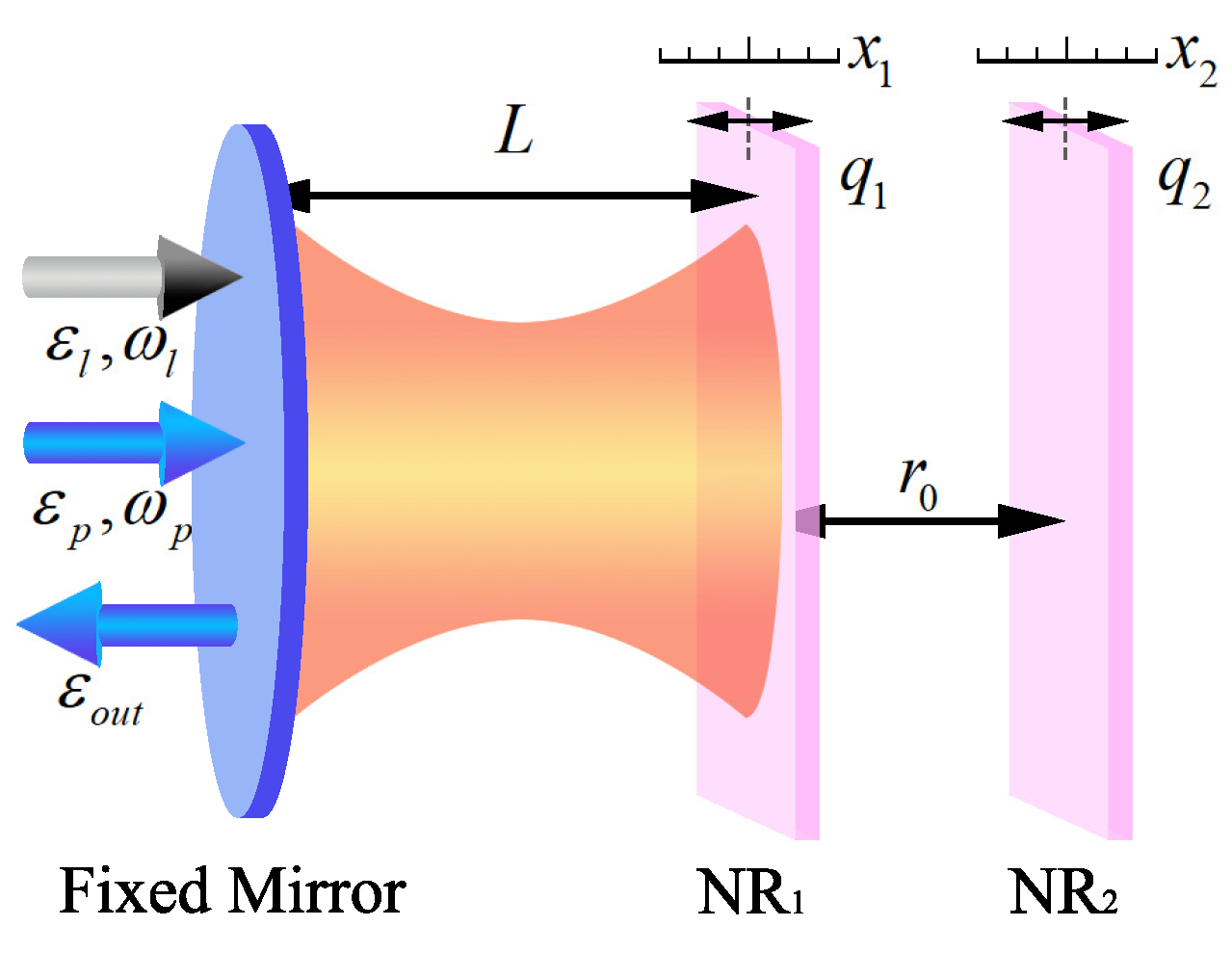
2. Theoretical Model

The model under study is an optomechanical system which consists of a fixed mirror and two nanomechanical resonators (NR1 and NR2), as shown in Figure 1. NR1 is coupled to the cavity field via radiation pressure, and coupled to the extracavity NR2 with tunable Coulomb interaction. To produce the tunable Coulomb interaction, NR1 and NR2 are charged by the bias gate voltage with q 1 and q 2 , respectively. NR1 and NR2 are separated by a distance r 0 , and the small displacements of which respect to their equilibrium positions are denoted by x 1 and x 2 , respectively. The optomechanical cavity with length L is driven by a strong coupling field E l with frequency ω l and a weak probe field E p with frequency ω p . The output field due to the interacting process is denoted by E out .
The Hamiltonian of the optomechanical system is given by
H ^ = H ^ opt + H ^ mech + H ^ int + H ^ C + H ^ drive ,
where H ^ opt is the Hamiltonian of the single-mode cavity, H ^ mech describes the mechanical vibration of NR 1 and NR 2 , H ^ int is the Hamiltonian of the interaction between the cavity field and NR 1 caused by radiation pressure, H ^ C represents the Coulomb interaction between the charged NR 1 and NR 2 , and H ^ drive is the Hamiltonian of the optical field driving the cavity. Specific expressions of the above Hamiltonian read
H ^ opt = ω c c c ,
H ^ mech = p 1 2 2 m 1 + 1 2 m 1 ω 1 2 x 1 2 + p 2 2 2 m 2 + 1 2 m 2 ω 2 2 x 2 2 ,
H ^ int = g c c x 1 ,
H ^ C = λ x 1 x 2 ,
H ^ drive = i η c κ C i n t c C i n * t c ,
where ω c is the frequency of the single-mode cavity field, c c is the annihilation (creation) operator, NRj are approximated as damped harmonic oscillators with effective mass m j , resonance frequency ω j , decay rate Γ j , and momentum operator p j ( j = 1 , 2 ), g = ω c / L is the coupling strength between NR1 and the cavity field due to radiation pressure, λ = q 1 q 2 / ( 2 π ε 0 r 0 3 ) , κ is the cavity decay rate, C i n ( t ) is the amplitude of the input flux of the cavity, and η c is the coupling parameter that can be continuously adjusted.
Based on the Heisenberg–Langgevin equation, A / t = 1 / i [ A , H ] + Λ A , in which A is a mechanic quantity, Λ A is a noise term, and in a frame rotating at the coupling frequency ω l , ı.e., A = A ˜ e i ω l t , we can obtain
x ˙ 1 = p 1 m 1 ,
p ˙ 1 = m 1 ω 1 2 x 1 λ x 2 + g c c Γ 1 p 1 + δ F 1 t ,
x ˙ 2 = p 2 m 2 ,
p ˙ 2 = m 2 ω 2 2 x 2 λ x 1 Γ 2 p 2 + δ F 2 t ,
c ˙ = κ 2 + i Δ c g x 1 c + η c κ C i n e i ω l t + ( 1 η c ) κ δ S t ,
where Δ c = ω c ω l is the detuning of the coupling field to the bare cavity, Γ j are the decay rates of NRj ( j = 1 , 2 ), δ F 1 , δ F 2 and δ S are quantum and Brownian noise with zero mean value.
The cavity is driven by a strong coupling field and a weak probe field; thus, the input flux amplitude can be expressed as C i n ( t ) = C ¯ i n + δ C i n t e i ω l t , with C ¯ i n = C l and δ C i n ( t ) = C p e i ω p ω l t , where C j = E j / ω j , ( j = l , p ), C l ( C p ) is the amplitude of the strong coupling (weak probe) field, E l ( E p ) is the power of the strong coupling (weak probe) field.

3. Solutions and Double OMIT

We focus on the steady-state response of the system; thus, the mean-field approximation Q c = Q c can be adopted; then, the mean value equations of Equation (3) are given by
x ˙ 1 = p 1 m 1 ,
p ˙ 1 = m 1 ω 1 2 x 1 λ x 2 + g c c Γ 1 p 1 ,
x ˙ 2 = p 2 m 2 ,
p ˙ 2 = m 2 ω 2 2 x 2 λ x 1 Γ 2 p 2 ,
c ˙ = κ 2 + i Δ c g x 1 c + η c κ C i n e i ω l t ,
which is a set of nonlinear equations, and the steady-state response of the system in the frequency domain is composed of many frequency components. To investigate response of the probe field, we use a standard procedure in the sideband theory and assume the solutions with the following form [14]
x 1 = x 1 s + x 1 + e i δ t + x 1 e i δ t ,
p 1 = p 1 s + p 1 + e i δ t + p 1 e i δ t ,
x 2 = x 2 s + x 2 + e i δ t + x 2 e i δ t ,
p 2 = p 2 s + p 2 + e i δ t + p 2 e i δ t ,
c = c s + c + e i δ t + c e i δ t ,
where δ = ω p ω l , each quantity contains three items O s , O + , O (with O x 1 , p 1 , x 2 , p 2 , c ), corresponding to the responses at the frequencies ω l , ω p , and 2 ω l ω p in the original frame, respectively. In the case of O s O ± , Equation (4) can be solved by treating O ± as perturbations. After substituting Equation (5) into Equation (4), and ignoring the second-order terms, we obtain the steady-state mean values of the system as
p 1 s = p 2 s = 0 , x 1 s = g c s 2 m 1 ω 1 2 + λ u , x 2 s = u x 1 s , c s = η c κ i Δ + κ / 2 C l ,
with Δ = Δ c g x 1 s and u = λ / ( m 2 ω 2 2 ) .
When frequency difference δ between the coupling and probe fields is close to the resonant frequency ω 1 of NR 1 , coherent oscillations occur, i.e., photons and phonons are coupled due to radiation pressure, which in turn causes Stokes scattering and anti-Stokes scattering. Stokes scattering is strongly suppressed when the system is operated in the resolved sideband κ ω 1 region; thus, we assume that only anti-Stokes scattering exists in the optical resonant cavity [24,40,41], which means c 0 , the term in Equation (5e) corresponding to the response at frequency ω p in the original frame is reserved, and reads
c + = η c κ C p i Δ δ + κ 2 + 2 i β ω 1 ξ 1 G ,
in which β = | c s | 2 g 2 / ( 2 m 1 ω 1 ) , ξ 1 = δ 2 ω 1 2 + i δ Γ 1 , ξ 2 = δ 2 ω 2 2 + i δ Γ 2 and G = 2 λ 2 / ( m 1 m 2 ξ 2 ) .
Using input-output relation of the cavity, we obtain
C out ( t ) = C in t η c κ c t , = S l e i ω l t + S p e i ω p t η c κ c e i 2 ω l ω p t ,
with S l = C l η c κ c s , S p = C p η c κ c + corresponding to amplitude of the output field at frequency ω l and ω p , respectively. For the convenience of using spectral decomposition method to analyze the interference effect of the system, we define the dimensionless absorption function of the probe field as t a = 1 S p / C p , which reads
t a = η c κ i Δ δ + κ 2 + 2 i β ω 1 ξ 1 G ,
and absorption of the probe field in the system can be described by | t a | 2 .
Shown in Figure 2 is the absorption | t a | 2 as a function of δ ω and coupling power E l . δ ω = ( δ ω 1 ) / ω 1 is the dimensionless detuning from the central frequency of the sideband in units of ω 1 . System parameters are given by λ l = 1064 nm, L = 25 mm, r 0 = 50 μ m, ω 1 = ω 2 = 2 π × 947 × 10 3 Hz, the quality factor Q 1 = ω 1 / Γ 1 ( = Q 2 = ω 2 / Γ 2 ) = 6700 , m 1 = m 2 = 145 ng , κ = 2 π × 215 × 10 3 Hz , and η c = 1 / 2 in critical coupling [33,42].
The strength change of | t a | 2 is on the bottom surface, and three solid lines are absorption spectra for three typical coupling powers E l = 2 × 10 4 W, 2 × 10 2 W, and 1 × 10 1 W. When the Coulomb interaction is absent ( λ = 0 ), as shown in Figure 2a, we can see that a transparency window is opened at the center of the spectrum, and the width of the transparency increases with increasing coupling power; thus, the OMIT occurs. The physics behind this phenomenon is that the coupling and probe fields generate a radiation pressure oscillating at frequency δ . When δ is close to the resonance frequency ω 1 of NR1, coherent oscillation between the photon and phonon leads to anti-Stokes scattering at frequency ω p which interferes destructively with the probe field, absorption at δ ω = 0 is hugely suppressed. When NR2 coupling with NR1 via Coulomb interaction, as shown in Figure 2b for Coulomb coupling strength λ = 8 × 10 36 Hz / m 2 , a absorption peak is produced at the center of the absorption spectrum compared to the spectrum in Figure 2b. Thus, the single transparency window is split into two transparency windows, i.e., double-OMIT occurs.

4. Analysis of Interference Effect in Double OMIT

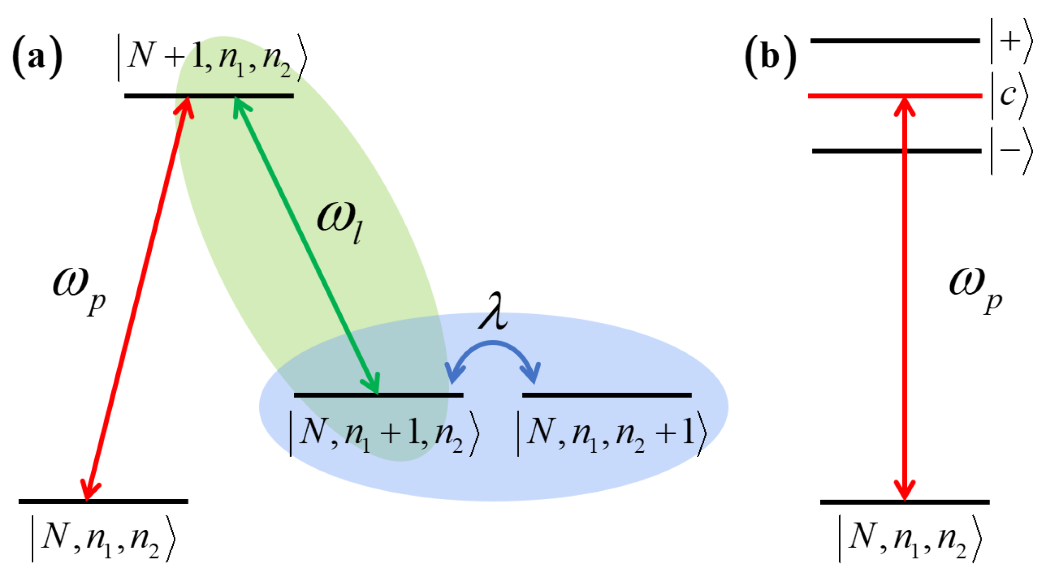
4.1. Dressed States Analysis and Numerical Models

To further explore the nature of interference effect in double OMIT, we demonstrate a detailed absorption spectrum decomposition method based on a qualitative analysis of energy-level diagram of the system and a numerical method well developed in study of EIT.
Shown in Figure 3a is the energy-level diagram of the optomechanical system, | N , n 1 , n 2 is coupled to | N , n 1 + 1 , n 2 via a two-photon process, and transition | N , n 1 + 1 , n 2 | N , n 1 , n 2 + 1 is induced by the Coulomb interaction. The optical tunnel | N , n 1 + 1 , n 2 | N + 1 , n 1 , n 2 and acoustic tunnel | N , n 1 + 1 , n 2 | N , n 1 , n 2 + 1 can be resolved as three states | + , | c and | in dressed state picture, as shown in Figure 3b. The energy gap between the three dressed states is depending on both E l and λ , but the strength of the optical coupling is much larger compared to the Coulomb interaction. Therefore, we can assume that contribution of E l is much larger than λ (which will be proved later in Figure 5a). Thus, three regions can be divided according to the coupling power based on the spectrum decomposition method.
First, when the coupling power is low, distance between the three dressed states is small, and the dressed states share a reservoir. The double-OMIT spectrum comprises one broad and positive Lorentzian centered at the origin, and two narrow and negative Lorentzians symmetrically located on both sides of the central one. Thus, the absorption spectrum in this region can be expressed as
A EIT = s 2 δ ω 2 + γ 2 s int 2 ( δ ω δ int ) 2 + γ int 2 s int 2 ( δ ω + δ int ) 2 + γ int 2 ,
where ± δ int are the positions where interference occurs, and the last two terms are the interference terms, s, γ , s int , with γ int being parameters of corresponding Lorentzians.
Second, when the coupling power is high, distance between the three dressed states is large, the dressed states decay into distinct reservoirs. The absorption spectrum can be treated as ATS, which comprises three Lorentzians at positions corresponding to states | c , | + , and | , and can be expressed as
A ATS = s c 2 δ ω 2 + γ c 2 + s + 2 ( δ ω δ + ) 2 + γ + 2 + s 2 ( δ ω + δ ) 2 + γ 2 ,
where s j , γ j , δ j ( j = c , + , ) are parameters of corresponding Lorentzians, and due to the symmetrical contributions of states | ± , one can assume that s + = s , δ + = δ , and γ + = γ for simplicity.
At last, in the intermediate region, the dressed states reservoirs are only partially distinct, the absorption spectrum has both contributions of interference effect and ATS effect.

4.2. Analysis of Interference Effect with E l

In the next step, based on Equations (10) and (11), a set of typical E l is chosen to analyze the interference effect in the double-OMIT system. Shown in Figure 4 are fitting results of the absorption spectrum via models A EIT ( s int , δ int , γ int , s , γ ) , and A ATS ( s + , δ + , γ + , s c , γ c ) in different regions, system parameters are the same as those given in Figure 2b.
In Figure 4a, the blue solid line is the absorption profile for E l = 2 × 10 4 W, and a relatively perfectly fitting result (red dashed–dotted line) can be obtained by using fitting model A EIT . To understand the detail of the interference effect, we also plot the interference terms in Equation (10) as the green dashed line in the figure. It can be seen that the opening of the double transparency windows only depends on the destructive interference effect at ± δ int . In the intermediate region, e.g., E l = 2 × 10 2 W, as shown Figure 4b, the absorption profile has a good fit to A ATS model (red dashed–dotted line). The gray filled region is contribution by the interference, and the difference is negative in the range of the transparency windows. Thus, we can obtain that the opening of the double transparency windows is contributed by both the destructive interference effect and normal mode splitting. At last, when the coupling power is large enough, e.g., E l = 1 × 10 1 W, we can obtain a relatively perfect fit by using the A ATS model, shown as a red dashed–dotted line in Figure 4c. The contribution of the interference effect at the transparency windows can be neglected, and the opening of the transparency windows mainly depends on mode splitting induced by the coupling field.
To verify our fitting results, we also demonstrate a test based on Akaike’s information criterion (AIC) [36] to determine whether A EIT or A ATS are dominant in different coupling power regions. The Akaike weights w i = e I i / 2 / N j = 1 e I j / 2 , where I i = 2 log L i + 2 k i , with L i being the maximum likelihood of the candidate model A i , and 2 k i being responsible for the penalty on the number of parameters used in the fitting number of penalties. There are only two models ( N = 2 ) involved in our study; thus, we can rewrite w i as w EIT = e I EIT / 2 / ( e I EIT / 2 + e I ATS / 2 ) with w EIT + w ATS = 1 .
The per-point weights w i as a function of the coupling field power E l are shown in Figure 4d. It can be observed that the A EIT model dominates first, and rapidly reduces to zero with increasing of E l , and the A ATS model dominates gradually on the contrary. This proves that our fitting results above are solid.

4.3. Analysis of Interference Effect with λ

In addition, the double-OMIT system can be used to realize precision measurement of Coulomb interaction, force sensing, etc. [24,33], due to that width between the two transparency windows changes following change of the interaction strength. Thus, it is also very important to clarify the influence of the Coulomb interaction strength λ on the interference effect in the system.
As shown in Figure 5a, with increasing of the Coulomb interaction strength λ , the absorption profile | t a | 2 turns from a single transparency window to double transparency windows. We can clearly observe that width of the central absorption peak is broadening; however, the width of the absorption peaks on both sides are gradually narrowing. As a result, the distance between the two transparency windows D linearly increases, as shown in Figure 5b, this property has significant for precision measurement. In addition, the distance between the absorption peaks on both sides change slightly, which indirectly proves the assumption about influence of λ on energy gap between the dressed states when proposing the fitting model.
Shown in Figure 6 are results of interference analysis in the system, and to make the results more obvious, we let the system works in the intermediate region with E l = 2 × 10 2 W . We choose two typical λ , from Figure 6a,b, we can see that the absorption profiles for two λ all fit well to the A ATS model, and destructive interference occurs in the transparency window regions. However, as shown in the color-filled area of the two figures, the contributions of the destructive interference for the suppression of absorption are basically the same. Thus, we can reach the conclusion that, when the optical tunnel | N , n 1 + 1 , n 2 | N + 1 , n 1 , n 2 is stronger than the acoustic tunnel | N , n 1 + 1 , n 2 | N , n 1 , n 2 + 1 , the Coulomb interaction strength λ has almost no effect on the interference effect of the system, it only determines the position of the dips. In addition, it must be mentioned that the absorption peaks in Figure 6b exhibit slight deformation compared to the Lorentzian for a strong Coulomb interaction. If λ is large enough to be comparable to optical coupling, the system will work in nonlinear region, i.e., λ not only determines positions of the transparency, but also affects splitting of the dressed states, which will cause distance between the two transparency windows to change nonlinearly. In other words, it exceeds the measurement limit. To deal with this situation, one needs to modify the interaction Hamiltonian H ^ int in a theoretical description.

5. Discussion

In conclusion, we have demonstrated a detailed investigation of the nature of the interference effects in the double-OMIT system. Based on the spectrum decomposition method, we have divided three regions according to the coupling field power, and found that the opening of transparency windows is dominated by the destructive interference in the weak coupling power region, but by normal mode splitting in the strong coupling power region. In the intermediate region, both destructive interference and normal mode splitting make contributions. In addition, we have also found that the linear correlation between the Coulomb interaction strength and the distance between the two transparency windows can be kept when the Coulomb coupling is much weaker than the optical coupling in the system. Otherwise, the system would work in the nonlinear region. These results obtained here not only provide a more detailed understanding of the interference properties in optomechanical systems, but also have certain significance for precise measurements via optomechanical systems.

Author Contributions

Conceptualization, C.T.; methodology, C.T.; software, S.L.; validation, S.L.; formal analysis, S.L. and C.T.; investigation, S.L. and Z.H.; resources, S.L.; data curation, S.L.; writing— original draft preparation, S.L.; writing—review and editing, S.L., D.L. and C.T.; visualization, S.L.; supervision, C.T.; project administration, C.T.; funding acquisition, C.T. All authors have read and agreed to the published version of the manuscript.

Funding

This research was funded by Natural Science Foundation of Shandong (Grant No. ZR2021MA035), Shandong Province Higher Educational Youth Innovation Team Development Program (No. 2023RW065).

Institutional Review Board Statement

Not applicable.

Informed Consent Statement

Not applicable.

Data Availability Statement

Data underlying the results presented and the original calculation draft in this paper are not publicly available at this time but may be obtained from the authors upon reasonable request.

Conflicts of Interest

The authors declare no conflicts of interest.

References

  1. Weis, S.; Rivière, R.; Deléglise, S.; Gavartin, E.; Arcizet, O.; Schliesser, A.; Kippenberg, T.J. Optomechanically induced transparency. Science 2010, 330, 1520–1523. [Google Scholar] [CrossRef]
  2. Huang, S.M.; Agarwal, G.S. Normal-mode splitting and antibunching in Stokes and anti-Stokes processes in cavity optomechanics: Radiation-pressure-induced four-wave-mixing cavity optomechanics. Phys. Rev. A 2010, 81, 033830. [Google Scholar] [CrossRef]
  3. Safavi-Naeini, A.H.; Alegre, T.M.; Chan, J.; Eichenfield, M.; Winger, M.; Lin, Q.; Hill, J.T.; Chang, D.E.; Painter, O. Electromagnetically induced transparency and slow light with optomechanics. Nature 2011, 472, 69–73. [Google Scholar] [CrossRef] [PubMed]
  4. Han, Y.; Cheng, J.; Zhou, L. Electromagnetically induced transparency in a cavity optomechanical system with an atomic medium. J. Phys. B At. Mol. Opt. Pys. 2011, 44, 165505. [Google Scholar] [CrossRef]
  5. Aspelmeyer, M.; Kippenberg, T.J.; Marquardt, F. Cavity optomechanics. Rev. Mod. Phys. 2014, 86, 1391–1452. [Google Scholar] [CrossRef]
  6. Liu, Y.C.; Li, B.B.; Xiao, Y.F. Electromagnetically induced transparency in optical microcavities. Nanophotonics 2017, 6, 789–811. [Google Scholar] [CrossRef]
  7. Xiong, H.; Wu, Y. Fundamentals and applications of optomechanically induced transparency. Appl. Phys. Rev. 2018, 5, 031305. [Google Scholar] [CrossRef]
  8. Wang, C.Q.; Jiang, X.F.; Zhao, G.G.; Zhang, M.Z.; Hsu, C.W.; Peng, B.; Stone, A.D.; Jiang, L.; Yang, L. Electromagnetically induced transparency at a chiral exceptional point. Nat. Phys. 2020, 16, 334–340. [Google Scholar] [CrossRef]
  9. Tarhan, D.; Huang, S.M.; Müstecaplıoğlu, O.E. Superluminal and ultraslow light propagation in optomechanical systems. Phys. Rev. A 2013, 87, 013824. [Google Scholar] [CrossRef]
  10. Jing, H.; Özdemir, Ş.K.; Geng, Z.; Zhang, J.; Lü, X.Y.; Peng, B.; Yang, L.; Nori, F. Optomechanically-induced transparency in parity-time-symmetric microresonators. Sci. Rep. 2015, 5, 9663. [Google Scholar] [CrossRef]
  11. Lü, H.; Wang, C.Q.; Yang, L.; Jing, H. Optomechanically Induced Transparency at Exceptional Points. Phys. Rev. Appl. 2018, 10, 014006. [Google Scholar] [CrossRef]
  12. Agarwal, G.S.; Huang, S.M. Optomechanical systems as single-photon routers. Phys. Rev. A 2012, 85, 021801. [Google Scholar] [CrossRef]
  13. Du, L.; Liu, Y.M.; Jiang, B.; Zhang, Y. All-optical photon switching, router and amplifier using a passive-active optomechanical system. EPL 2018, 122, 24001. [Google Scholar] [CrossRef]
  14. Zhang, J.Q.; Li, Y.; Feng, M.; Xu, Y. Precision measurement of electrical charge with optomechanically induced transparency. Phys. Rev. A 2012, 86, 053806. [Google Scholar] [CrossRef]
  15. Zhang, Y.W.; Chen, G. Nonlinear effects in a Floquet-driven optomechanical system. Phys. Rev. A 2023, 107, 023520. [Google Scholar] [CrossRef]
  16. Jiménez-Marín, E.; Torres-Torres, C.; Mercado-Zú niga, C.; Vargas-García, J.; Trejo-Valdez, M.; Cervantes-Sodi, F.; Torres-Martínez, R. Interferometrically-controlled electrical currents in carbon nanotubes coated by platinum nanoparticles. Opt. Laser Technol. 2016, 85, 35–40. [Google Scholar] [CrossRef]
  17. Pan, G.; Yu, G.; Xiao, R.; Zhai, C. Tunable multiple optomechanically induced transparency and slow/fast light via optical parametric amplifiers in a distant electro-optical system. Eur. Phys. J. D 2024, 78, 1–8. [Google Scholar] [CrossRef]
  18. Huang, S.M.; Agarwal, G.S. Electromagnetically induced transparency with quantized fields in optocavity mechanics. Phys. Rev. A 2011, 83, 043826. [Google Scholar] [CrossRef]
  19. Fiore, V.; Dong, C.H.; Kuzyk, M.C.; Wang, H.L. Optomechanical light storage in a silica microresonator. Phys. Rev. A 2013, 87, 023812. [Google Scholar] [CrossRef]
  20. Wen, J.G.; Zhen, Y. Double optomechanically induced transparency in coupled-resonator system. Opt. Commun. 2014, 333, 261–264. [Google Scholar]
  21. Feng, L.J.; Gong, S.Q. Two-photon blockade generated and enhanced by mechanical squeezing. Phys. Rev. A 2021, 103, 043509. [Google Scholar] [CrossRef]
  22. Kalita, S.; Kumar, P.; Kanamoto, R.; Bhattacharya, M.; Sarma, A.K. Pump-probe cavity optomechanics with a rotating atomic superfluid in a ring. Phys. Rev. A 2023, 107, 013525. [Google Scholar] [CrossRef]
  23. Qu, K.; Agarwal, G.S. Fano resonances and their control in optomechanics. Phys. Rev. A 2013, 87, 063813. [Google Scholar] [CrossRef]
  24. Ma, P.C.; Zhang, J.Q.; Xiao, Y.; Feng, M.; Zhang, Z.M. Tunable double optomechanically induced transparency in an optomechanical system. Phys. Rev. A 2014, 90, 043825. [Google Scholar] [CrossRef]
  25. Wang, Q.; Zhang, J.Q.; Ma, P.C.; Yao, C.M.; Feng, M. Precision measurement of the environmental temperature by tunable double optomechanically induced transparency with a squeezed field. Phys. Rev. A 2015, 91, 063827. [Google Scholar] [CrossRef]
  26. Zhang, X.Y.; Zhou, Y.H.; Guo, Y.Q.; Yi, X.X. Double optomechanically induced transparency and absorption in parity-time-symmetric optomechanical systems. Phys. Rev. A 2018, 98, 033832. [Google Scholar] [CrossRef]
  27. Agarwal, G.S.; Huang, S.M. Electromagnetically induced transparency in mechanical effects of light. Phys. Rev. A 2010, 81, 041803. [Google Scholar] [CrossRef]
  28. Xiong, H.; Si, L.G.; Lv, X.Y.; Yang, X.X.; Wu, Y. Review of cavity optomechanics in the weak-coupling regime: From linearization to intrinsic nonlinear interactions. Sci. China Phys. Mech. Astron. 2015, 58, 1–13. [Google Scholar] [CrossRef]
  29. Liu, J.H.; He, G.Q.; W, Q.; Yu, Y.F.; Wang, J.D.; Zhang, Z.M. Fraction-order sideband generation in an optomechanical system. Opt. Lett. 2020, 45, 5169–5172. [Google Scholar] [CrossRef]
  30. Zhang, J.; Peng, B.; Kim, S.; Monifi, F.; Jiang, X.F.; Li, Y.H.; Yu, P.; Liu, L.Q.; Liu, Y.X.; Alù, A.; et al. Optomechanical dissipative solitons. Nature 2021, 600, 75–80. [Google Scholar] [CrossRef]
  31. Dobrindt, J.M.; Wilson-Rae, I.; Kippenberg, T.J. Parametric Normal-Mode Splitting in Cavity Optomechanics. Phys. Rev. Lett. 2008, 101, 263602. [Google Scholar] [CrossRef] [PubMed]
  32. Gröblacher, S.; Hammerer, K.; Vanner, M.R.; Aspelmeyer, M. Observation of strong coupling between a micromechanical resonator and an optical cavity field. Nature 2009, 460, 724–727. [Google Scholar] [CrossRef] [PubMed]
  33. Huang, S.M.; Deng, L.; Chen, A.X. Electromagnetically induced transparency with quantized fields in a dissipative optomechanical system. Phys. Rev. A 2023, 107, 013524. [Google Scholar] [CrossRef]
  34. Agarwal, G.S. Nature of the quantum interference in electromagnetic-field-induced control of absorption. Phys. Rev. A 1997, 55, 2467–2470. [Google Scholar] [CrossRef]
  35. Abi-Salloum, T.Y. Electromagnetically induced transparency and Autler–Townes splitting: Two similar but distinct phenomena in two categories of three-level atomic systems. Phys. Rev. A 2010, 81, 053836. [Google Scholar] [CrossRef]
  36. Anisimov, P.M.; Dowling, J.P.; Sanders, B.C. Objectively Discerning Autler–Townes Splitting from Electromagnetically Induced Transparency. Phys. Rev. Lett. 2011, 107, 163604. [Google Scholar] [CrossRef] [PubMed]
  37. Peng, B.; Özdemir, Ş.K.; Chen, W.J.; Nori, F.; Yang, L. What is and what is not electromagnetically induced transparency in whispering-gallery microcavities. Nat. Commun. 2014, 5, 5082. [Google Scholar] [CrossRef]
  38. Zhou, Y.; Chu, L.R.; Liu, Q.; Wang, C.K.; Tan, C.H. Analysis of quantum interference properties in Λ- and V-type schemes in rare-earth-ion-doped crystal with inhomogeneous broadening. J. Opt. Soc. Am. B 2019, 36, 2534–2544. [Google Scholar] [CrossRef]
  39. Wu, H.D.; Ruan, Y.P.; Li, Z.X.; Dong, M.X.; Cai, M.; Tang, J.S.; Tang, L.; Zhang, H.; Xiao, M.; Xia, K.Y. Fundamental Distinction of Electromagnetically Induced Transparency and Autler–Townes Splitting in Breaking the Time-Reversal Symmetry. Laser Photonics Rev. 2022, 16, 2100708. [Google Scholar] [CrossRef]
  40. Xiong, H.; Si, L.G.; Zheng, A.S.; Yang, X.X.; Wu, Y. Higher-order sidebands in optomechanically induced transparency. Phys. Rev. A 2012, 86, 013815. [Google Scholar] [CrossRef]
  41. Xiong, H.; Huang, Y.M.; Wan, L.L.; Wu, Y. Vector cavity optomechanics in the parameter configuration of optomechanically induced transparency. Phys. Rev. A 2016, 94, 013816. [Google Scholar] [CrossRef]
  42. Gigan, S.; Böhm, H.; Paternostro, M.; Blaser, F.; Langer, G.; Hertzberg, J.; Schwab, K.C.; Bäuerle, D.; Aspelmeyer, M.; Zeilinger, A. Self-cooling of a micromirror by radiation pressure. Nature 2006, 444, 67–70. [Google Scholar] [CrossRef]
Figure 1. (Color online) Schematic diagram of the optomechanical system which consists of a fixed mirror and two nanomechanical resonators (NR1 and NR2). NR1 and NR2 are charged by the bias gate voltage with q 1 and q 2 , respectively. NR1 and NR2 are separated by a distance r 0 , and the small displacements of which respect to their equilibrium positions are denoted by x 1 and x 2 , respectively. The optomechanical cavity with length L is driven by a strong coupling field E l with frequency ω l and a weak probe field E p with a frequency of ω p . The output field due to the interacting process is denoted by E out .
Photonics 11 00289 g001
Figure 2. (Color online) Absorption | t a | 2 as a function of δ ω 1 and coupling power E l for (a) without the Coulomb interaction characterized by λ = 0 , (b) with the Coulomb coupling strength λ = 8 × 10 36 Hz / m 2 .
Photonics 11 00289 g002
Figure 3. (Color online) (a) Energy-level diagram of the optomechanical system, where N, n 1 , n 2 are quantum number of the cavity photon and NR1 and NR2 phonons, respectively. (b) Energy-level diagram of the optomechanical system in the dressed state picture.
Photonics 11 00289 g003
Figure 4. (Color online) (ac) Fitting results of the absorption | t a | 2 for Coulomb interaction strength λ = 8 × 10 36 Hz / m 2 via fitting models A ATS and A EIT in different regions, and only the best fitting results are kept. (a) E l = 2 × 10 4 W , with a good fit to A EIT ( 0.0001 , 0.0860 , 0.0002 , 0.1252 , 0.1262 ) . (b) E l = 2 × 10 2 W , with a good fit to A ATS ( 0.0355 , 0.1655 , 0.0337 , 0.0192 , 0.0191 ) . (c) E l = 1 × 10 1 W , with a good fit to A ATS ( 0.0439 , 0.3251 , 0.0457 , 0.0068 , 0.0069 ) . (d) Per-point weights ω i as a function of coupling field power E l .
Photonics 11 00289 g004
Figure 5. (Color online) (a) Absorption | t a | 2 as a function of δ ω and Coulomb interaction strength λ with E l = 2 × 10 2 W , the other system parameters are the same as those given above, and two solid lines are the typical absorption profiles with different λ fitted in the following. (b) The distance D between the two transparency windows as a function of λ .
Photonics 11 00289 g005
Figure 6. (Color online) Fitting results of the absorption | t a | 2 via fitting models A ATS and A EIT with different Coulomb interaction strength λ . (a) λ = 6 × 10 36 Hz / m 2 , with a good fit to A ATS ( 0.0337 , 0.1526 , 0.0331 , 0.0140 , 0.0143 ) . (b) λ = 1.2 × 10 37 Hz / m 2 , with a good fit to A ATS ( 0.0264 , 0.1944 , 0.0268 , 0.0358 , 0.0349 ) .
Photonics 11 00289 g006
Disclaimer/Publisher’s Note: The statements, opinions and data contained in all publications are solely those of the individual author(s) and contributor(s) and not of MDPI and/or the editor(s). MDPI and/or the editor(s) disclaim responsibility for any injury to people or property resulting from any ideas, methods, instructions or products referred to in the content.

