Article

Generation of Propagation-Dependent OAM Self-Torque with Chirped Spiral Gratings

by
Ruediger Grunwald
1,*,
Mathias Jurke
1,
Max Liebmann
2,
Alexander Treffer
3 and
Martin Bock
1
1
Max-Born-Institute for Nonlinear Optics and Short Pulse Spectroscopy, Max-Born-Strasse 2a, 12489 Berlin, Germany
2
HOLOEYE Photonics AG, Volmerstrasse 1, 12489 Berlin, Germany
3
SENTECH Instruments GmbH, Schwarzschildstraße 2, 12489 Berlin, Germany
*
Author to whom correspondence should be addressed.
Photonics 2024, 11(5), 463; https://doi.org/10.3390/photonics11050463
Submission received: 2 May 2024 / Revised: 11 May 2024 / Accepted: 13 May 2024 / Published: 15 May 2024
(This article belongs to the Special Issue Structured Light Beams: Science and Applications)

Abstract

:
The application of non-uniform spiral gratings to control the structure, topological parameters and propagation of orbital angular momentum (OAM) beams was studied experimentally with coherent near-infrared light. Adapted digital spiral grating structures were programmed into the phase map of a high-resolution liquid-crystal-on-silicon spatial light modulator (LCoS-SLM). It is shown that characteristic spatio-spectral anomalies related to Gouy phase shift can be used as pointers to quantify rotational beam properties. Depending on the sign and gradient of spatially variable periods of chirped spiral gratings (CSGs), variations in rotation angle and angular velocity were measured as a function of the propagation distance. Propagation-dependent self-torque is introduced in analogy to known local self-torque phenomena of OAM beams as obtained by the superposition of temporally chirped or phase-modulated wavepackets. Applications in metrology, nonlinear optics or particle trapping are conceivable.

1. Introduction

During the last few decades, the generation, detection and application of structured light [1,2] including orbital angular momentum (OAM) beams [3,4,5,6,7,8,9,10,11,12,13,14,15] have been the subject of intensive research. In particular, the wide spectral bandwidths and high intensities of ultrashort-pulsed lasers opened new prospects for optical communication, materials processing, nonlinear spectroscopy, metrology or particle manipulation. Characteristic anomalies in the spectral and spatial domains in the vicinity of singularities, so-called “spectral eyes” [16,17,18,19,20,21], result from wavelength-dependent Gouy phase shift and spectral interference [22,23,24]. Related spectral re-distribution effects were previously detected by highly resolved spectral mapping of femtosecond OAM laser pulses. The calculation of local (first-order) and global (higher-order) spectral statistical moments [25] was used to extract topological and rotational beam parameters. Moreover, the statistical formalism provides appropriate tools for advanced applications, e.g., deep encryption, imaging, ranging, selective excitation or optical processing. For the variable generation and manipulation of OAM beams by tunable phase and/or amplitude maps, the following approaches are of technical interest: (a) MEMS spiral phase plates (SPPs) [26], (b) digital mirror devices (DMD) [27], (c) liquid crystal spatial light modulators (SLMs) [28,29] and (d) cascaded [29] or combined [30,31] systems. Singularities in wave fields can be generated by phase dislocations in forked rectilinear or spiral grating structures [5,32,33,34,35]. Spiral phase gratings (SPGs) act as diffractive axicons with an axially extended focal zone and a helical wavefront [36,37,38]. SPGs were developed for THz applications [39] and for the generation of acoustic vortices with electro-mechanical transducers [40,41,42,43,44,45,46,47,48].
DMDs are of interest for high-speed spatial phase modulation in the optical range because they have an order of magnitude higher switching speed [49]. Their phase stroke, linearity, fill factor and further parameters, however, are still not satisfactory. A specific advantage of the liquid-crystal-on-silicon (LCoS)-SLM technique [50,51,52,53,54,55] consists in the large number of addressable small pixels with, at the same time, phase-shifting functionality at high dynamic range and a calibrated phase. This combination is still not fully available with DMDs. Because of the high structural flexibility, it is possible to write even complex reconfigurable diffractive optical elements (DOEs) into advanced types of SLMs.
Recently, we reported on the first proof-of-principle experiments with high-resolution phase-only LCoS-SLMs as programmable non-uniform SPGs [56]. Here, we present the results of continuing studies and a more detailed discussion. In particular, the concept of OAM self-torque is extended by a propagation-dependent acceleration or deceleration of angular rotation as an alternative approach which promises specific applications in metrology, particle manipulation, frequency conversion and other fields.

2. Spiral Phase Gratings

The mechanism of axial beam shaping with spiral DOEs is based on a radial-to-axial transformation. Radial variations of the grating period modulate the angular spectrum of interfering conical beams along the propagation path. If the rms radius of an illuminating Gaussian beam is held constant, the far-field divergence of OAM beams generated by grating dislocations scales linearly with the OAM [57]. The reflective operation of LCoS-SLMs requires either transforming the shape of the programmed optical elements into its elliptical projection as a function of the angle of incidence or working at sufficiently small incident angles. In a slightly simplified picture, one can distinguish between selected cases of planar spiral gratings with respect to their silhouette (shape of the edge):
(A)
Grating completely filling a circle;
(B)
Grating completely filling an ellipse;
(C)
Toroidal grating filling a single annulus (one ring);
(D)
Grating filling the center and annulus (center, one ring);
(E)
Multi-toroidal grating filling multiple annuli (N rings).
Furthermore, the uniformity and symmetry properties of spiral gratings can be described by the spatial distribution of the grating period p(r,θ) in polar representation with r and θ as the radial and azimuthal coordinates, respectively:
(1)
Constant grating period (uniform Archimedean grating);
(2)
Radially monotonically increasing spatial frequency (positive chirp);
(3)
Radially monotonically decreasing spatial frequency (negative chirp);
(4)
Grating period depending on θ (oscillating chirp).
Selected configurations with single spirals or composed uniaxial spirals of identical rotational orientation are, without claiming to be exhaustive, depicted in Figure 1. Recently, asymmetric elliptical gratings of type (C,1) were proposed for shaping toroidal vortex beams [58].
Previously it was demonstrated by experiments with stationary spiral axicons that the rotation of characteristic spectral features can be controlled via the grating period p(r) [23]. With SLMs, more free parameters and temporal modulation (within the limits of the cut-off frequency) became available. In particular, a continuous radial variation of p(r), as well as a discontinuous section-wise design, can be used to obtain a propagation-dependent rotation. The radial variation of the inverse period ν = p−1 is the signed spatial frequency chirp dν/dr.
The imaging properties, spectral response and diffraction efficiency of non-uniform binary gratings strongly depend on the individual phase structure of the grating, the angular spectrum of the illuminating beam, and the beam’s frequency spectrum, polarization and coherence.
The m-th-order convergence angle β of a reflective spiral axicon at small incident angles as a function of the wavelength λ and the period p(r) can be approximately described via the grating equation:
β ( r ) = sin 1 m · λ p ( r )
One should note the convention that the angle β in Equation (1) is the half-total convergence angle. For each β(r), one can define corresponding radially dependent “focal distances” f(r):
f ( r ) = r t a n sin 1 m · λ p r
A radially uniform Archimedean spiral grating axicon generates Bessel-like intensity profiles [33]. For non-uniform SPGs, the propagation characteristics depend on the individual 2D phase envelope. In the particular case (A,3), the outer parts of a continuous grating with smaller p diffract the light more strongly than the central parts. This can lead to an overlap and interference of partial beams. Case (4) is obtained by a grating transformation by linear stretching in one direction (mapping a circle to an ellipse), which is equivalent to illumination at oblique incidence [56]. In this case, p oscillates with increasing rotation angle φ and passes two maxima and two minima within every full rotational period of Δφ = 2π. Therefore, one has to expect that the rotational parameters exhibit corresponding extrema with increasing propagation distance if the angle of incidence is not fully compensated.

3. Propagation-Dependent Self-Torque

In the spatial domain, the propagation-dependent Gouy rotation of “spectral eyes” of polychromatic OAM beams around singularities [22,23,24] can be described by a local angular gradient:
Ω ( z ) = φ z
where the rotational angle φ(z) is the pointer position of a virtual connecting line between the centroids of two “spectral eyes” at propagation distance z. This gradient results from the interference of all diffracted spectral contributions. In the temporal domain, one can formally define a corresponding angular velocity at time t:
Ω t , z = φ t = c · Ω ( z )
(c = speed of light in vacuum). For an ultrashort OAM pulse, Equation (4) describes the speed of angular rotation as a function of the pulse travel time. The temporal derivative of the angular velocity is a measure of rotational acceleration or deceleration and can be interpreted as a kind of “self-torque” [56]:
ξ t , z = Ω t , z t = 2 φ t 2 = c · Ω z t
Originally, the term “self-torque” was used for the temporal acceleration of an OAM at a fixed axial coordinate obtained by the superposition of frequency-modulated wavepackets [59,60] or by interfering co-rotating wavepackets of different rotation speeds [23]. The introduction of a propagation-dependent acceleration as described by Equation (5) enables us to generalize the term “self-torque”, covering both of the following:
(i)
A local, interference-type, superposition-generated self-torque (SST);
(ii)
A nonlocal, propagation-type self-torque (PST).
In special cases, these types can also appear simultaneously, e.g., by the interference of overlapping contributions from SPGs with positive chirp, as mentioned above.
SST is relevant for OAM-selective laser–matter interaction processes on an ultrashort time scale and plays an important role, e.g., for high harmonics generation [59,60], the resonant excitation of quasi-particles by rotating ring-lattices [61], spin-to-orbit conversion, or optical spin Hall effects in focused beams [62]. PST may also stimulate specific applications which require sensibility against distances or pulse travel times.

4. Experimental Techniques

4.1. Experimental Setup

The experimental setup used for the adaptive singular optics experiments is schematically drawn in Figure 2. SPGs were programmed into the pixel matrix of a 10-megapixel (4 K) phase-only reflective LCoS-SLM (GAEA, HOLOEYE Photonics, Berlin, Germany, pixel size 3.74 µm). Phase linearity was ensured by spectral calibration of grey-scale values. Additionally, the contrast was optimized by adaptively varying the base level. The SLM was illuminated by a linearly polarized Ti/sapphire laser oscillator (center wavelength tunable between 780 and 810 nm) after expanding the beam diameter 5× to completely fill the active area of the microdisplay. A movable and rotatable near-infrared-enhanced, black-and-white CMOS camera (Thorlabs, Bergkirchen, Germany, DCC 324ONN, 1280 × 1024 pixels, pixel size 5.5 µm, 60 fps with 50× and 100× objective lenses) served as a matrix detector.
The spatial scale of the camera was adjusted and aberrations were evaluated by imaging the focal plane of a lithographically fabricated orthogonal microlens array (Heinrich Hertz Institute, Berlin, Germany) with 32 µm pitch as a reference. Saturation was avoided by attenuating the intensity with a rotatable polarizer. For programming SLM phase patterns and for image analysis, two separate computers with related software packages were applied.
To characterize the twist and self-torque phenomena of OAM beams, the spectral Gouy rotation [22,23,24] was exploited. The approach enables a direct visualization of spectrally resolved internal vortex structures instead of analyzing complex spiral interference patterns [63]. In contrast to time-consuming fiber-scanning techniques [25], the single-shot detection of propagation-dependent azimuthal angles of spectral eyes with a matrix camera works much faster. From previous studies, it was known that a channel bandwidth in the few-nanometer range is sufficient to reliably separate spectral eyes [23]. Therefore, the spectral resolution of a tilted ultra-narrowband metal interference filter for 794 nm (LC-HBP-794.9/1–25, Laser Components, Olching, Germany, total tilt range 20°) was used to identify the positions of spectral eyes and to adjust the transmission range.

4.2. Elliptical Continuously Chirped Gratings

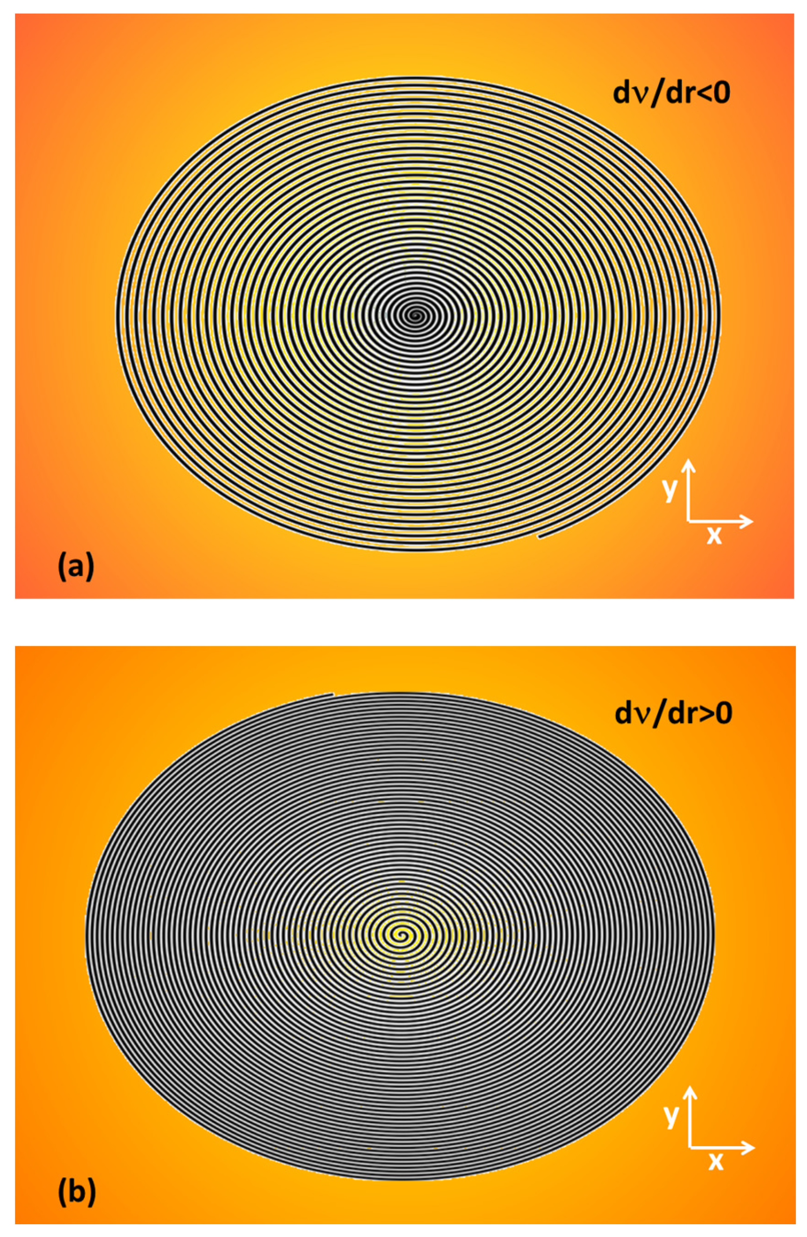
The radial change in the grating periods of spiral gratings with perfectly linear negative and positive spatial frequency chirp for realistic parameters is plotted in Figure 3a and Figure 3b, respectively. To match non-zero tilt angles, the gratings have to be deformed to an elliptical shape. The stretched periods expected for an incident angle of α = 45° can be compared to the case of normal incidence. The SPG with negative spatial frequency chirp was designed to be an Archimedean spiral with 37 windings and periods increasing from origin to the rim from 29 µm to 55 µm along the minor axis. The periods of the SPG with positive spatial frequency chirp along the minor axis decreased from 58 µm down to 34 µm along 55 windings. More details on the design strategy for linearly chirped SPGs can be found in Appendix A.
The spirals used in the experiments were generated with online available freeware (Inkscape 1.0). The resulting radial dependence of the grating periods deviated from perfect linear functions, in particular close to the center and the rim. The real radial chirp functions programmed into the SLM phase maps are plotted in Figure 4.
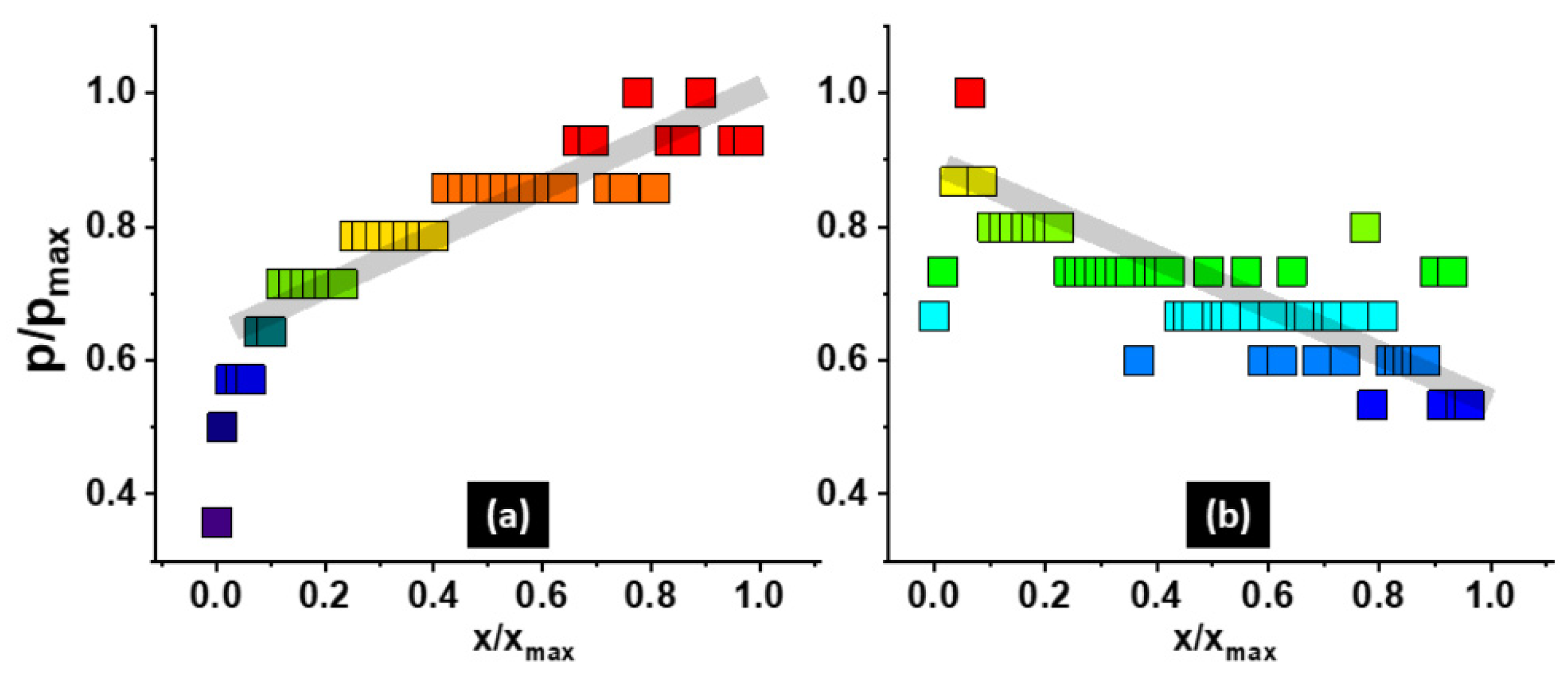
The real progression of periods (Figure 5) was determined by image processing software (ImageJ, Version 1.53k). The scattering of the data points along cuts is caused by the limited resolution of digital sampling at the microscale.
Because of the pixel size of the SLM of 3.74 µm, the efficiency of the DOEs is limited by the Nyquist–Shannon sampling theorem. At the highest spatial frequencies (grating periods < 30 µm), where the number of sampling points is <5, the design is less perfect.
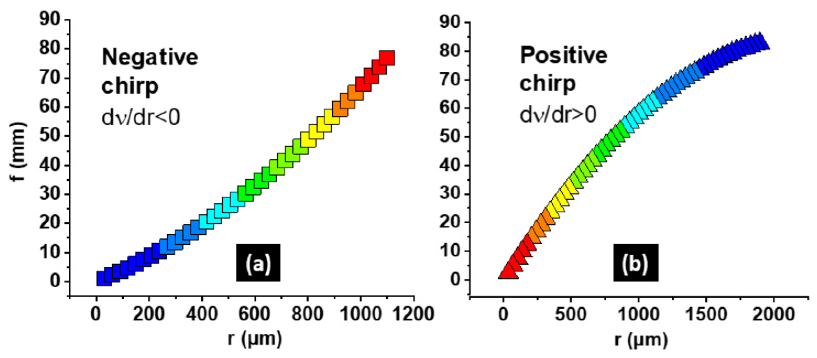
Figure 6 shows the “focal distances” in the m = 1st order as a function of SPG radii calculated by Equation (2) for perfect symmetric gratings with positive and negative chirp for a wavelength of 787 nm (for spiral parameters, see above). Despite representing rough approximations, the graphs may give a qualitative indication of the expected axial beam shaping behavior.
One can recognize that the functions zF(r) are slightly nonlinear and, over the relevant spectral range of about 20 nm, nearly independent of the laser wavelength (regarding the spectral bandwidth, see also Section 5.4).

4.3. Non-Uniform Toroidal Gratings

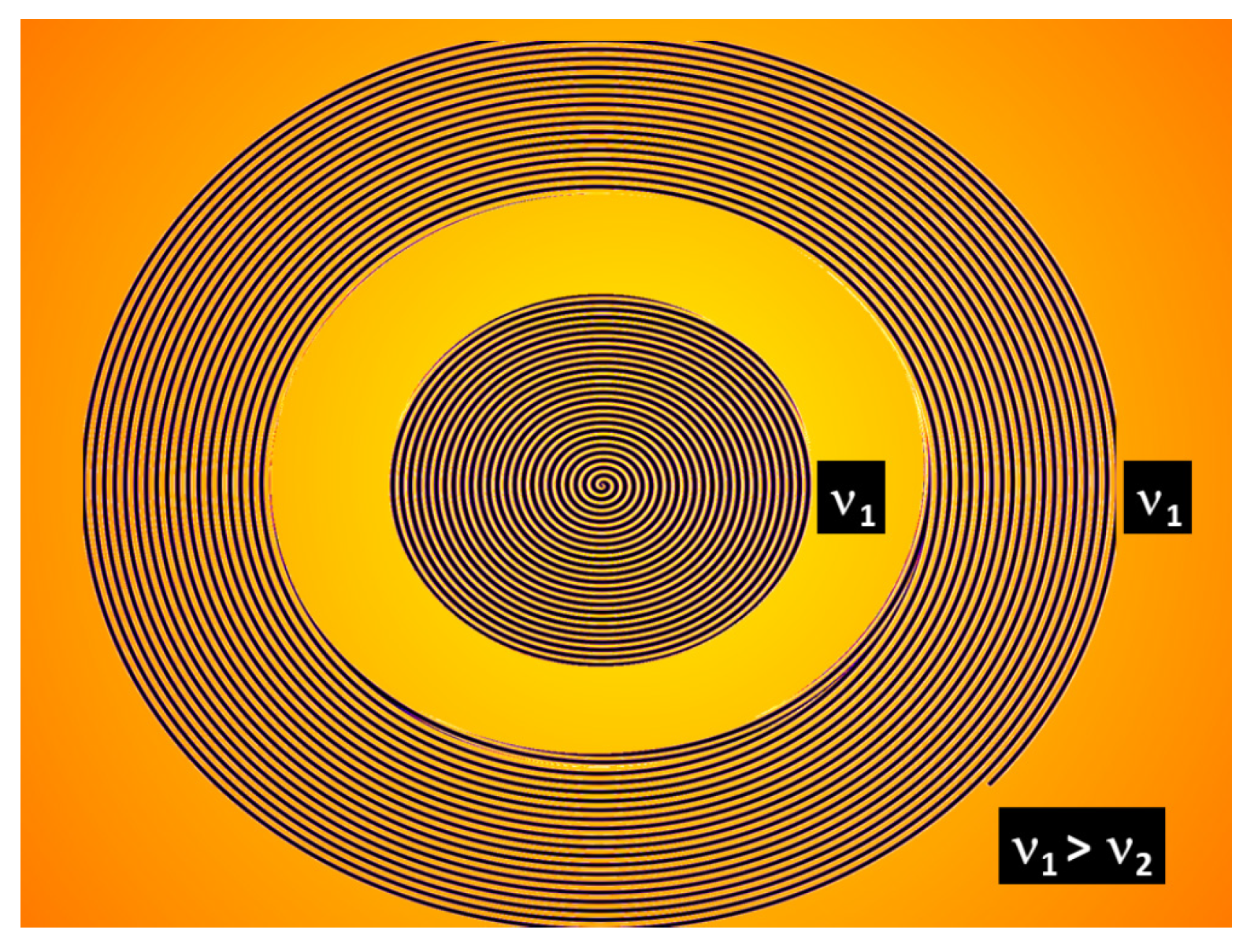
Alternative experiments were performed with SPGs consisting of an elliptical torus surrounding a central elliptical SPG. Figure 7 shows such a grating structure of type (D,4) (see Figure 1i). Both partial gratings are stretched in one direction but, contrary to the SPGs in Figure 4a,b, without spatial frequency chirp along radial cuts.
The inner SPG, however, has a higher spatial frequency. The periods in the directions of minor and major axes are 17 µm and 45 µm for the inner elliptical SPG, while those for the surrounding torus are 21 µm and 54 µm, respectively. The partial gratings are not spatially chirped for each azimuthal angle but are stretched in the x-direction. The gap has a depth of about 0.56 times the torus width and 0.24 times the outer torus diameter.

5. Experimental Results

5.1. Spectral Filtering

To select characteristic “spectral eyes” as indicators for the spectral Gouy rotation, the spectral filter was adjusted to an appropriate tilt state at which the broadband background signal is attenuated while both the blue- and red-shifted parts appear at comparable intensity. Spectra were detected by a high-resolution spectrometer (HR 2000, Ocean Optics, Duiven, The Netherlands). The selectivity was verified by alternatingly attenuating the maxima [56]. This enabled us to simultaneously detect the blue- and red-shifted contributions at maximum intensity and contrast (Figure 8). An optimum wavelength range was found between 784 nm and 787 nm at an FWHM of about 7 nm.

5.2. Grating Aberrations at Oblique Incidence

The application of an SLM enables us to adaptively correct for angular-dependent aberrations. From the literature, it is known that spiral gratings at oblique incidence generate typical diamond-shaped light patterns [33]. In our investigations, we studied the response of this effect on the tilt angle at the relevant parameters. For an elliptically stretched SPG with a design angle of 45°, it was found that the angular tolerance is critical. Even for an angular mismatch smaller than 2°, a rhomboidal distortion was clearly observed. The internal structure of the aberrated field looks complex and has some similarity to higher-order laser modes. This effect and, additionally, the appearance of asymmetrically distributed higher grating diffraction orders are visible in Figure 9 for a misadjusted 45° SPG illuminated at a central wavelength of about 790 nm.

5.3. Propagation-Dependent Self-Torque

Propagation experiments with spectral selection were performed with three types of non-uniform spiral gratings:
(1)
SPG-1, corresponding to Figure 4b (elliptical, negative chirp);
(2)
SPG-2, corresponding to Figure 4a (elliptical, positive chirp);
(3)
SPG-3, corresponding to Figure 7 (elliptical and toroidal, different periods).
The spectral rotation was detected by measuring the rotation of the connecting lines between the “spectral eyes”. In accordance with the expected saw-tooth-like axial oscillation of Gouy rotation caused by the accumulated phase anomaly [23,64], particular distance ranges with detectable rotation were identified. As an example, a selected set of intensity maps for the elliptical SPG-2 with positive spatial frequency chirp is shown in Figure 10 for axial distances between z = 20.0 mm and z = 20.6 mm.
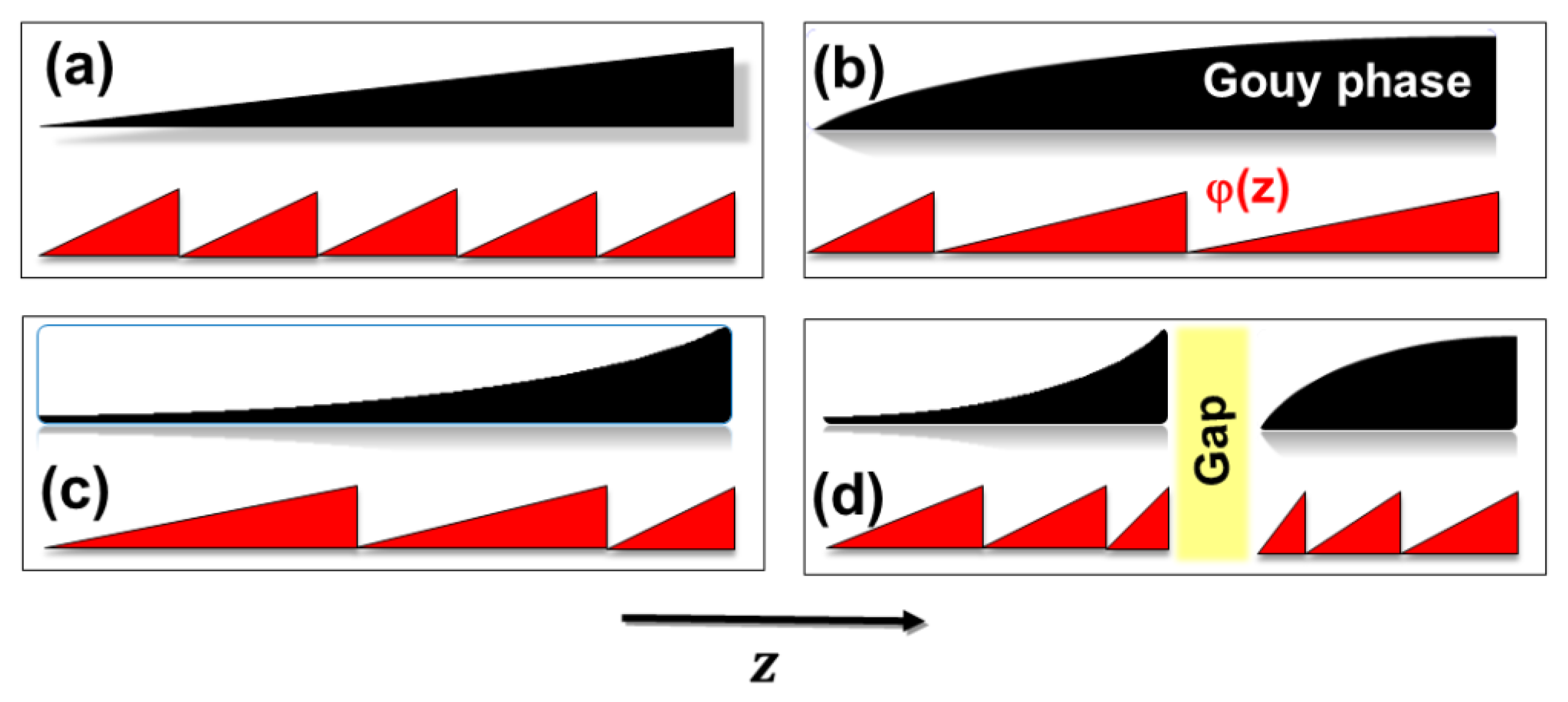
With increasing distance, however, the contrast decreased so that meaningful measuring results were only obtained within the first part (few millimeters) of the interference zone. The detected pattern rotates counter-clockwise, as expected from the programmed spiral orientation. In contrast to the case of radially constant grating periods, the changing focal distances of chirped spiral axicons generate accordion-like stretched angular compartments and, thus, correspondingly modified accumulated Gouy phase shifts. This phenomenon, which is schematically depicted in Figure 11, also leads to an axial change of the ramps in the saw-tooth-like function φ(z).
Figure 12a–c show the measured propagation-dependent rotational angles φ(z) for the three gratings SPG-1, SPG-2 and SPG-3 (corresponding to the structures in Figure 4a,b and Figure 7). The maximum measuring distances for SPG-1, SPG-2 and SPG-3 were chosen to be 6 mm, 28 mm and 16.9 mm, respectively.
In all cases, a distinct rotational behavior was typically observed through discrete intervals in the z-direction interrupted by zones of minimal rotation. The distortions result from the complex spatio-spectral interference caused by the detailed phase structure of the pixelated DOE (a particular influencing factor for possible systematic distortions is briefly discussed in Section 5.4.
On the basis of the detected ramps of angular rotation, i.e., steep and nearly linearly increasing parts of φ(z), corresponding axial angular velocity gradients Ω(z) were calculated according to Equation (3). The resulting curves are plotted in Figure 13a–c.
To compare the distribution of experimental data with theoretical estimations, the “focal length” at the rim of the inner spiral of SPG-3 was calculated by applying Equation (2). The red dashed line in Figure 13c corresponds to the starting position of the gap. It is obvious that this distance can only be a rough approximation because of the influence of beam divergence, aberrations, parasitic interference and other factors (see also the next paragraph). The presented angular gradients confirm that the investigated types of non-uniform gratings enable the generation of accelerated, decelerated and more complex spectral rotational behavior, which can be interpreted as a specific, propagation-dependent kind of self-torque (PST).

5.4. Influence of Grating Talbot Effect

The interaction of coherent light fields with periodical amplitude and/or phase objects like gratings leads to self-imaging effects [65]. Depending on the grating period p and the wavelength λ, the distances of planes with replicated periodicity (Talbot distances)
d T   ~   k · 2 p 2 λ       ( k   =   integer   number )
or fractal self-images can generate distortions in competition with the axially periodic Gouy phase effects. In our case, the grating periods have to be relatively large due to the sampling theorem. Because of the quadratic dependence on p, the resulting Talbot distances can be large enough to match the cycles of rotation. For example, the first Talbot planes for periods of 30 µm, 40 µm and 50 µm at a wavelength of 800 nm are expected to appear at distances of 2.25 mm, 4.0 mm and 6.25 mm, respectively. Thus, the effect is relevant for our experimental parameters and should be observed in general design considerations.

6. Conclusions

In summary, it was demonstrated that the angular velocity of OAM beams can be controlled by programming digital non-uniform spiral gratings into the calibrated phase map of a reflective high-resolution LCoS-SLM. Propagation-dependent rotation parameters were analyzed by detecting the spectral Gouy rotation, i.e., the twist of characteristic blue- and red-shifted areas around the singularity, on a matrix camera. The spectral signatures of the rotating spectral anomaly were clearly identified and separated by narrow band-pass filtering. The flexible generation of grating structures enables radial variations of grating periods with positive or negative spatial frequency chirp, elliptical gratings and separated concentric rings of gratings.
The resulting axial modulations of the angular velocity indicated accelerated and decelerated orbital angular momenta. The propagation-dependent derivation of the speed of rotation (propagation-dependent self-torque, PST) is therefore interpreted as a specific type of self-torque in analogy to the local temporal self-torque (superposition-generated self-torque, SST), which was previously reported in the literature (see refs. [59,60]). This generalization allows us to distinguish between local, nonlocal and mixed generation mechanisms of self-torque. PST could be of interest for specific applications like space-variant interaction scenarios for ultrafast space–time wavepackets, vortex metrology, optical processing, adaptive micro-accelerators, depth-selective laser materials processing or tweezers.
A more precise prediction of the axial light distribution requires us to solve the complex diffraction problem, e.g., by starting from the Rayleigh–Fano equation for scattering from rough surfaces, as was shown for circular gratings. By Laplace and inverse Laplace transforms, the problem can be reduced to a tractable form [66]. An extended theoretical treatment including spatio-temporal coupling and dispersion effects, non-uniform phase envelope, specific aberrations and self-imaging mechanisms, however, remains the subject of future studies.
Possible improvements with respect to the experimental methods could be obtained by replacing the combination of a spectral filter and camera with a high-resolution hyperspectral camera. Moreover, a detailed study of the spatio-temporal dynamics of ultrashort-pulsed PST phenomena, e.g., in nonlinear media, seems to be worthwhile.

Author Contributions

Conceptualization and methodology, R.G., M.L. and M.B.; experiments R.G., M.J., M.L. and A.T.; data analysis, R.G. and M.B.; writing—original draft preparation, R.G.; writing—review and editing, R.G. and M.B.; visualization, R.G., M.L., M.J., M.B. and A.T.; project administration and funding acquisition, R.G. The authors declare that no support by AI was used. All authors have read and agreed to the published version of the manuscript.

Funding

This research was funded in part by Deutsche Forschungsgemeinschaft (DFG), project MAXWELL III, grant number GR1782/16-2.

Institutional Review Board Statement

Not applicable.

Informed Consent Statement

Not applicable.

Data Availability Statement

Measuring data can be provided by the authors.

Acknowledgments

Experimental resources including lab space and high-power laser systems were kindly provided by Elsaesser and Erik Nibbering (MBI). Jahns and his team (FernUniversity, Hagen) designed the lithographic DOE structures that were used in preceding experiments with refractive–diffractive spiral axicon arrays. Advanced approaches were particularly inspired by this collaboration.

Conflicts of Interest

Max Liebmann and Alexander Treffer were employed by the company Holoeye Photonics (Germany) and SENTECH Instruments (Germany), respectively. The remaining authors declare that the research was conducted in the absence of any commercial or financial relationships that could be construed as a potential conflict of interest.

Appendix A. Design Parameters for Linearly Chirped SPGs

The design of fully filled circular spiral gratings with radially linearly varying periods has to take into account the maximum radius rmax, the total number of windings N, the minimum period p0 and the linear increment Δp per winding:
r m a x = N · p 0 + p · j = 0 N 1 j
The sum term provides
j = 0 N 1 j = N ( N 1 ) 2
From Equations (A1) and (A2), one obtains a maximum grating radius of
r m a x = N · p 0 + p · N 2 N 2
For nonlinear types of spirals, the constant increment has to be replaced by a winding-number-dependent increment, Δp(N).

References

  1. Rubinsztein-Dunlop, H.; Forbes, A.; Berry, M.V.; Dennis, M.R.; Andrews, D.L.; Mansuripur, M.; Denz, C.; Alpmann, C.; Banzer, P.; Bauer, T.; et al. Roadmap on structured light. J. Opt. 2017, 19, 133001. [Google Scholar] [CrossRef]
  2. Bliokh, K.Y.; Karimi, E.; Padgett, M.J.; Alonso, M.A.; Dennis, M.R.; Dudley, A.; Forbes, A.; Zahedpour, S.; Hancock, S.W.; Milchberg, H.M.; et al. Roadmap on structured waves. J. Opt. 2023, 25, 103001. [Google Scholar] [CrossRef]
  3. Nye, J.F.; Berry, M.V. Dislocations in wave trains. Proc. R. Soc. Lond. 1974, 336, 165–190. [Google Scholar] [CrossRef]
  4. Coullet, P.; Gil, L.; Rocca, F. Optical vortices. Opt. Commun. 1989, 73, 403–408. [Google Scholar] [CrossRef]
  5. Soskin, M.S.; Vasnetsov, M.V. Singular optics. Prog. Opt. 2001, 42, 219–276. [Google Scholar] [CrossRef]
  6. Dennis, M.R.; O’Holleran, K.; Padgett, M.J. Singular optics: Optical vortices and polarization singularities. Prog. Opt. 2009, 53, 293–363. [Google Scholar] [CrossRef]
  7. Yao, A.; Padgett, M.J. Orbital angular momentum: Origins, behavior and applications. Adv. Opt. Photonics 2011, 3, 161–204. [Google Scholar] [CrossRef]
  8. Wang, X.; Nie, Z.; Liang, Y.; Wang, J.; Li, T.; Jia, B. Recent advances on optical vortex generation. Nanophotonics 2018, 7, 1533–1556. [Google Scholar] [CrossRef]
  9. Shen, Y.; Wang, Y.; Xie, Z.; Min, C.; Fu, X.; Liu, Q.; Gong, M.; Yuan, X. Optical vortices 30 years on: OAM manipulation from topological charge to multiple singularities. Life Sci. Appl. 2019, 8, 90. [Google Scholar] [CrossRef] [PubMed]
  10. Chen, R.; Zhou, H.; Moretti, M.; Wang, X.; Li, J. Orbital angular momentum waves: Generation, detection and emerging applications. IEEE Commun. Surv. Tutor. 2020, 22, 840–868. [Google Scholar] [CrossRef]
  11. Zhang, K.; Wang, Y.; Yuan, Y.; Burokur, S.N. A review of orbital angular momentum vortex beams generation: From traditional methods to metasurfaces. Appl. Sci. 2020, 10, 1015. [Google Scholar] [CrossRef]
  12. Fatkhiev, D.M.; Butt, M.A.; Grakhova, E.P.; Kutluyarov, R.V.; Stepanov, I.V.; Kazanskiy, N.L.; Khonina, S.N.; Lyubopytov, V.S.; Sultanov, A.K. Recent advances in generation and detection of orbital angular momentum optical beams—A review. Sensors 2021, 21, 4988. [Google Scholar] [CrossRef] [PubMed]
  13. Bai, Y.; Lv, H.; Fu, X.; Yang, Y. Vortex beam: Generation and detection of orbital angular momentum. Chin. Opt. Lett. 2022, 20, 012601. [Google Scholar] [CrossRef]
  14. Zhu, L.; Wang, J. A review of multiple optical vortices generation: Methods and application. Front. Optoelectron. 2019, 12, 52–68. [Google Scholar] [CrossRef]
  15. Forbes, A. Advances in orbital angular momentum lasers. IEEE J. Light. Technol. 2023, 41, 2079–2086. [Google Scholar] [CrossRef]
  16. Berry, M.V. Coloured phase singularities. New J. Phys. 2002, 4, 66. [Google Scholar] [CrossRef]
  17. Gbur, G.; Visser, T.D.; Wolf, E. Anomalous behavior of spectra near phase singularities of focus waves. Phys. Rev. Lett. 2002, 88, 013901. [Google Scholar] [CrossRef] [PubMed]
  18. Popescu, G.; Dogariu, A. Spectral anomalies at wave-front dislocations. Phys. Rev. Lett. 2002, 88, 183902. [Google Scholar] [CrossRef]
  19. Berry, M.V. Exploring the colours of dark light. New J. Phys. 2002, 4, 74. [Google Scholar] [CrossRef]
  20. Leach, J.; Padgett, M.J. Observation of chromatic effects near a white-light vortex. New J. Phys. 2003, 5, 154. [Google Scholar] [CrossRef]
  21. Zapata-Rodríguez, C.J. Analytical characterization of spectral anomalies in polychromatic aperture beams. Opt. Commun. 2006, 257, 9–15. [Google Scholar] [CrossRef]
  22. Liebmann, M.; Treffer, A.; Bock, M.; Elsaesser, T.; Grunwald, R. Spectral anomalies and Gouy rotation around the singularity of ultrashort vortex pulses. Opt. Express 2017, 25, 26076–26088. [Google Scholar] [CrossRef] [PubMed]
  23. Liebmann, M.; Treffer, A.; Bock, M.; Wallrabe, U.; Grunwald, R. Ultrashort vortex pulses with controlled spectral Gouy rotation. Appl. Sci. 2020, 10, 4288. [Google Scholar] [CrossRef]
  24. Bock, M.; Liebmann, M.; Elsaesser, T.; Grunwald, R. Gouy phase rotation in spectral maps of ultrashort vortex pulses. In Proceedings of the Conference on Lasers and Electro-Optics/CLEO Europe-Conference on Lasers and Electro-Optics/Europe—European Quantum Electronics/EQEC, Munich, Germany, 25–29 June 2017. [Google Scholar]
  25. Liebmann, M.; Treffer, A.; Bock, M.; Seiler, T.; Jahns, J.; Elsaesser, T.; Grunwald, R. Spectral meta-moments reveal hidden signatures of vortex pulses. EPJ Web Conf. 2019, 205, 01005. [Google Scholar] [CrossRef]
  26. Bock, M.; Brunne, J.; Treffer, A.; König, S.; Wallrabe, U.; Grunwald, R. Sub-3-cycle vortex pulses of tunable topological charge. Opt. Lett. 2013, 38, 3642–3645. [Google Scholar] [CrossRef] [PubMed]
  27. Chen, Y.; Fang, Z.-X.; Ren, Y.-X.; Gong, L.; Lu, R.-D. Generation and characterization of a perfect vortex beam with a large topological charge through a digital micromirror device. Appl. Opt. 2015, 54, 8030–8035. [Google Scholar] [CrossRef] [PubMed]
  28. Guo, S.F.; Liu, K.; Sun, H.X.; Zhang, J.X.; Gao, J.R. Generation of high-order Laguerre-Guassian beams by liquid crystal spatial light modulators. J. Quantum Opt. 2015, 21, 86–92. [Google Scholar] [CrossRef]
  29. Zhu, L.; Wang, J. Arbitrary manipulation of spatial amplitude and phase using phase-only spatial light modulators. Sci. Rep. 2014, 4, 7441. [Google Scholar] [CrossRef] [PubMed]
  30. Grunwald, R.; Jurke, M.; Bock, M.; Liebmann, M.; Bruno, B.P.; Gowda, H.; Wallrabe, U. High-flexibility control of structured light with combined adaptive optical systems. Photonics 2022, 9, 42. [Google Scholar] [CrossRef]
  31. Grunwald, R.; Jurke, M.; Bock, M.; Liebmann, M.; Bruno, B.P.; Gowda, H.; Wallrabe, U. Structuring light by combining spatial modulation and fast angular shaping. In Proceedings of the Complex Light and Optical Forces XVII, Photonics West, San Francisco, CA, USA, 28 January–2 February 2023; Volume 12436, p. 1243606. [Google Scholar] [CrossRef]
  32. Brand, G.F. Phase singularities in beams. Am. J. Phys. 1999, 67, 55–60. [Google Scholar] [CrossRef] [PubMed]
  33. Dyson, J. Circular and spiral diffraction gratings. Proc. R. Soc. Lond. Ser. A Math. Phys. Sci. 1958, 248, 93–106. [Google Scholar] [CrossRef]
  34. Vasara, A.; Turunen, J.; Friberg, A.T. Realization of general nondiffracting beams with computer-generated holograms. J. Opt. Soc. Am. A 1989, 6, 1748–1754. [Google Scholar] [CrossRef]
  35. Abramochkin, E.; Volostnikov, V. Spiral-type beams. Opt. Commun. 1993, 102, 336–350. [Google Scholar] [CrossRef]
  36. Pereiro-García, J.; García-de-Blas, M.; Geday, M.A.; Quintana, X.; Caño-García, M. Flat variable liquid crystal diffractive spiral axicon enabling perfect vortex beams generation. Sci. Rep. 2023, 13, 2385. [Google Scholar] [CrossRef] [PubMed]
  37. Musigmann, M.; Jahns, J.; Bock, M.; Grunwald, R. Refractive-diffractive dispersion compensation for optical vortex beams with ultrashort pulse durations. Appl. Opt. 2014, 53, 7304–7311. [Google Scholar] [CrossRef] [PubMed]
  38. Supp, S.; Jahns, J. Coaxial superposition of Bessel beams by discretized spiral axicons. J. Eur. Opt. Soc.-Rapid Publ. 2018, 14, 18. [Google Scholar] [CrossRef]
  39. Li, X.; Shen, Z.; Tan, Q.; Hu, W. High efficient metadevices for terahertz beam shaping. Front. Phys. 2021, 9, 659747. [Google Scholar] [CrossRef]
  40. Jiménez, N.; Picó, R.; Sánchez-Morcillo, V.; Romero-García, V.; García-Raffi, L.M.; Staliunas, K. Formation of high-order acoustic Bessel beams by spiral diffraction gratings. Phys. Rev. E 2016, 94, 053004. [Google Scholar] [CrossRef] [PubMed]
  41. Wang, T.; Ke, M.; Li, W.; Yang, Q.; Qiu, C.; Liu, Z. Particle manipulation with acoustic vortex beam induced by a brass plate with spiral shape structure. Appl. Phys. Lett. 2016, 109, 123506. [Google Scholar] [CrossRef]
  42. Li, W.; Ke, M.; Peng, S.; Liu, F.; Qiu, C.; Liu, Z. Rotational manipulation by acoustic radiation torque of high-order vortex beams generated by an artificial structured plate. Appl. Phys. Lett. 2018, 113, 051902. [Google Scholar] [CrossRef]
  43. Zhou, H.; Li, J.; Guo, K.; Guo, Z. Generation of acoustic vortex beams with designed Fermat’s spiral diffraction grating. J. Acoust. Soc. Am. 2019, 146, 4237–4243. [Google Scholar] [CrossRef] [PubMed]
  44. Jia, Y.; Sun, Z.; Li, J.; Zhao, L.; Liu, H.; Li, T.; Liu, S. MEMS Bessel beam acoustic transducer (MEMS-BBAT) with air-cavity lens based on spiral diffraction grating for particle trapping. In Proceedings of the 2022 IEEE International Ultrasonics Symposium (IUS), Venice, Italy, 10–13 October 2022. [Google Scholar] [CrossRef]
  45. Li, J.; Sun, Z.; Jia, Y.; Li, T.; Lu, H.; Zhao, L.; Liu, H.; Liu, S. MEMS first-order Bessel beam acoustic transducer for particle trapping and controllable rotating. In Proceedings of the 2023 IEEE 36th International Conference on Micro Electro Mechanical Systems (MEMS), Munich, Germany, 15–19 January 2023. [Google Scholar] [CrossRef]
  46. Muelas-Hurando, R.D.; Ealo, J.L.; Volke-Sepúlveda, K. Electro-active diffraction gratings for the generation of acoustic vortex beams. In Proceedings of the 2021 IEEE International Ultrasonics Symposium (IUS), Xi’an, China, 11–16 September 2021. [Google Scholar] [CrossRef]
  47. Muelas-Hurtado, R.D.; Ealo, J.L.; Pazos-Ospina, J.F.; Volke-Sepúlveda, K. Generation of multiple vortex beam by means of active diffraction gratings. Appl. Phys. Lett. 2018, 112, 084101. [Google Scholar] [CrossRef]
  48. Muelas-Hurtado, R.D.; Ealo, J.L.; Pazos-Ospina, J.F.; Volke-Sepulveda, K. Acoustic analysis of a broadband spiral source for the simultaneous generation of multiple Bessel vortices in air. J. Acoust. Soc. Am. 2018, 144, 3252–3261. [Google Scholar] [CrossRef] [PubMed]
  49. Ketchum, R.S.; Blanche, P.A. Diffraction efficiency characteristics for MEMS-based phase-only spatial light modulator with nonlinear phase distribution. Photonics 2021, 8, 62. [Google Scholar] [CrossRef]
  50. Serati, S.A.; Ewing, T.K.; Stockley, J.E. New developments in high-resolution liquid crystal spatial light modulators for wavefront control. Proc. SPIE 2002, 4825, 46–55. [Google Scholar] [CrossRef]
  51. Ohtake, Y.; Ando, T.; Fukuchi, N.; Matsumoto, N.; Ito, H.; Hara, T. Universal generation of higher-order multiringed Laguerre-Gaussian beams by using a spatial light modulator. Opt. Lett. 2007, 32, 1411–1413. [Google Scholar] [CrossRef] [PubMed]
  52. Matsumoto, N.; Ando, T.; Inoue, T.; Ohtake, Y.; Fukuchi, N.; Hara, T. Generation of high-quality higher-order Laguerre-Gaussian beams using liquid-crystal-on-silicon spatial light modulators. J. Opt. Soc. Am. A 2008, 25, 1642–1651. [Google Scholar] [CrossRef] [PubMed]
  53. Lazarev, G.; Hermerschmidt, A.; Krüger, S.; Osten, S. LCOS spatial light modulators: Trends and applications. In Optical Imaging and Metrology: Advanced Technologies, 1st ed.; Osten, W., Reingand, N., Eds.; Wiley-VCH: Weinheim, Germany; Berlin, Germany, 2012; pp. 1–28. [Google Scholar] [CrossRef]
  54. Gongjian, Z.; Man, Z.; Yang, Z. Wave front control with SLM and simulation of light wave diffraction. Opt. Express 2018, 26, 33543–33564. [Google Scholar] [CrossRef] [PubMed]
  55. Gao, Y.; Chen, Z.; Ding, J.; Wang, H.-T. Single ultra-high-definition spatial light modulation enabling highly efficient generation of fully structured vector beams. Appl. Opt. 2019, 58, 6591–6596. [Google Scholar] [CrossRef] [PubMed]
  56. Liebmann, M.; Treffer, A.; Bock, M.; Jurke, M.; Wallrabe, U.; Grunwald, R. Tailored spectral rotation of vortex pulses by non-uniform spiral phase gratings. Proc. SPIE 2021, 11701, 117010V. [Google Scholar] [CrossRef]
  57. Padgett, M.J.; Miatto, F.M.; Lavery, M.P.; Zeilinger, A.; Boyd, R.W. Divergence of an orbital-angular-momentum-carrying beam upon propagation. New J. Phys. 2015, 17, 023011. [Google Scholar] [CrossRef]
  58. Liu, W.; Cheng, J.; Wan, C. Generation of optical toroidal vortex with circular asymmetric gratings. arXiv 2024, arXiv:2404.11921. [Google Scholar] [CrossRef]
  59. Dorney, K.M.; Rego, L.; Brooks, N.J.; Nguyen, Q.; Liao, C.; Román, J.S.; Couch, D.E.; Liu, A.; Pisanty, E.; Lewenstein, M.; et al. Attosecond extreme ultraviolet beams with time-varying orbital angular momentum: The Self-Torque of Light. In Proceedings of the Conference on Lasers and Electro-Optics (CLEO), San José, CA, USA, 5–10 May 2019. [Google Scholar] [CrossRef]
  60. Rego, L.; Dorney, K.M.; Brooks, N.J.; Nguyen, Q.; Liao, C.-T.; Román, J.S.; Couch, D.E.; Liu, A.; Pisanty, E.; Lewenstein, M.; et al. Generation of extreme-ultraviolet beams with time-varying orbital angular momentum. Science 2019, 364, eaaw9486. [Google Scholar] [CrossRef] [PubMed]
  61. Yamane, K.; Sakamoto, M.; Murakami, N.; Morita, R.; Oka, K. Picosecond rotation of a ring-shaped optical lattice by using a chirped vortex-pulse pair. Opt. Lett. 2016, 41, 4597–4600. [Google Scholar] [CrossRef] [PubMed]
  62. Wu, Y.; Yu, P.; Liu, Y.; Wang, Z.; Li, Y.; Gong, L. Time-varying optical spin-orbit interactions in tight focusing of self-torqued beams. J. Light. Technol. 2023, 41, 2252–2258. [Google Scholar] [CrossRef]
  63. Grunwald, R.; Bock, M. Characterization of orbital angular momentum beams by polar mapping and Fourier Transform. Photonics 2024, 11, 296. [Google Scholar] [CrossRef]
  64. Kim, M.-S.; Scharf, T.; da Costa Assafrao, A.; Rockstuhl, C.; Pereira, S.F.; Urbach, H.P.; Herzig, H.P. Phase anomalies in Bessel-Gauss beams. Opt. Express 2012, 20, 28929–28940. [Google Scholar] [CrossRef]
  65. Berry, M.V.; Klein, S. Integer, fractional and fractal Talbot effects. J. Mod. Opt. 1996, 43, 2139–2164. [Google Scholar] [CrossRef]
  66. Elson, J.M. Mathematical analysis of gratings with circularly concentric grooves. J. Opt. Soc. Am. 1983, 73, 702–706. [Google Scholar] [CrossRef]
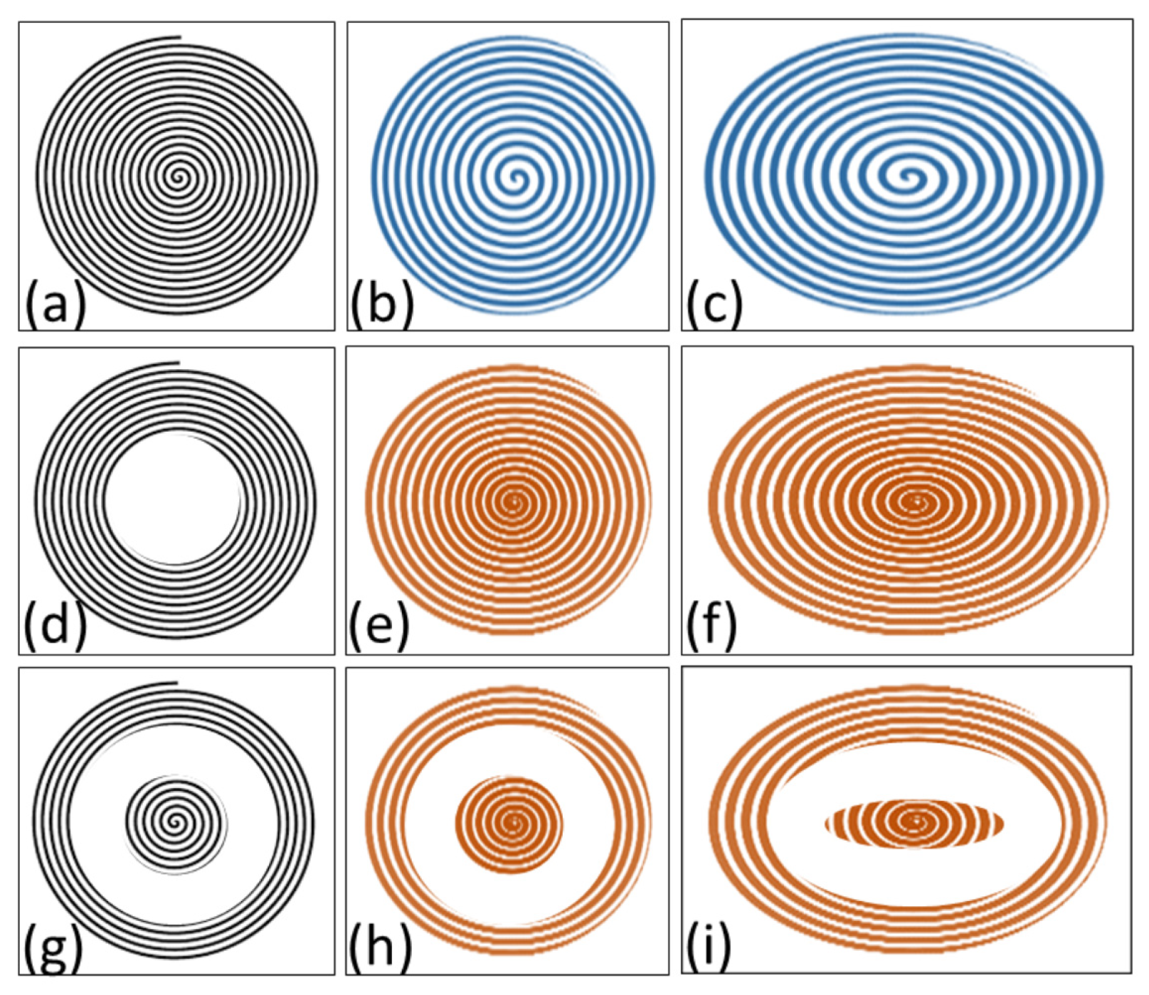
Figure 1. Selected types of uniform and non-uniform spiral gratings used in singular optics experiments in spectral domain (schematically); (a) case (A,1), (b) (A,2), (c) (B,2) and (B,4) with positive spatial chirp for each azimuthal angle, (d) (C,1), (e) (A,3) torus with negative spatial chirp, (f) (B,3), (g) (D,1), (h) (D,3), (i) (D,4). Patterns are transferred into calibrated SLM phase maps.
Photonics 11 00463 g001
Figure 2. Experimental setup for the rotational control of OAM beams in spectral domain (schematically). (L = laser, BF = rotatable narrow band-pass filter, RP = rotatable broadband polarizer, BE = beam expander, M = high-reflectance mirror, SLM = spatial light modulator, PC1 = computer for programming SLM, SPG = spiral phase grating, p(r) = radially dependent grating period, OAM = OAM beam, bSE and rSE = blue-shifted and red-shifted spectral eyes, CAM = movable camera with 50× and 100× objective lenses, PC2 = computer for data processing, φ (z) = local azimuthal rotation angle, Ω ( z ) = local angular velocity of spectral Gouy rotation).
Photonics 11 00463 g002
Figure 3. Theoretical perfectly linear curve progression of radially variable SPG periods with (a) negative (type B,3) and (b) positive (type B,2) spatial frequency chirp dν/dr (parameters for near-realistic conditions, number of spiral rotations: 37 and 55, along minor axes: increasing period between 29 µm and 55 µm, decreasing period between 58 µm and 34 µm, respectively). Depending on incident angle α, gratings are stretched in x-direction (perpendicular to the tilt axis) by a factor of cosα. Periods are compared for two tilt angles (α = 0°: circular SPG, α = 45°: elliptical SPG). Colors symbolize spatial frequency chirp (decreasing from blue to red, increasing from red to blue).
Photonics 11 00463 g003
Figure 4. Programmed SPG periods as used in experiments for beam shaping with SLM: (a) SPG-1 with negative spatial frequency chirp and 37 periods along the minor axes, increasing between 29 µm and 55 µm (type B,3), see Figure 1b; (b) SPG-2 with positive spatial frequency chirp and 55 periods, decreasing from 58 µm to 34 µm (type B,2), see Figure 1c.
Photonics 11 00463 g004
Figure 5. SPG periods as used in experiments determined by image analysis: SPG with (a) negative spatial frequency chirp or (b) positive spatial frequency chirp (number of spiral rotations: 37 and 55, along minor axes: increasing period between 29 µm and 55 µm, decreasing period between 58 µm and 34 µm, respectively). Colors symbolize spatial frequency chirp (decreasing from blue to red, increasing from red to blue).
Photonics 11 00463 g005
Figure 6. Radially dependent “focal distances” zF(r) (i.e., points of intersection of diffracted rays with the propagation axis) for perfect symmetric SPGs with negative (a) and positive chirp (b) for a wavelength of 787 nm (for geometrical parameters, see Figure 3a,b). Colors symbolize spatial frequency chirp (decreasing from blue to red, increasing from red to blue).
Photonics 11 00463 g006
Figure 7. Composite grating of type (D,4) consisting of an elliptical SPG (23 windings) centered in a surrounding toroidal SPG (18 windings) of different spatial frequency (periods in the directions of minor and major axes: 17 µm and 45 µm for the inner SPG, 21 µm and 54 µm for the torus, respectively).
Photonics 11 00463 g007
Figure 8. Selection of “spectral eyes” by a narrowband filter: spatial OAM beam intensity distributions for three filter curves with maximum transmission at (a) 782.08 nm, (b) 795.15 nm and (c) 798.22 nm. Simultaneous detection of blue-shifted and red-shifted parts at maximum contrast and signal was found between 784 nm and 787 nm, indicated by distinct double maxima in (b,e) (50× objective lens, negatively chirped SPG, z = 10 mm, distance between “spectral eyes”: 32 µm).
Photonics 11 00463 g008
Figure 9. Aberrations for spiral gratings at oblique incidence with structural and angular mismatch: (a) diamond-shaped distortion and higher diffraction orders up to m = ±3 of a uniform, non-adapted SPG at an incident angle of α = 45°; (b) distortion for a non-uniform SPG designed for α = 45° at an incident angle of α = 51°.
Photonics 11 00463 g009
Figure 10. Angular rotation of “spectral eyes” generated with positively chirped SPG-2 varying with increasing propagation distance from (ad) 20.0 mm to 20.6 mm for a selected sequence of intensity maps (AOI = 50 × 50 µm2, red and blue circles: red- and blue-shifted parts of the spectral anomaly, the line indicates the actual angle of rotation).
Photonics 11 00463 g010
Figure 11. Accumulated Gouy phase shift (black) and Gouy rotation angle (red) (schematically) for SPGs with (a) a constant period, (b) a negatively chirped period, (c) a positively chirped period and (d) a composite structure consisting of two zones with different constant periods separated by a spatial gap (yellow). A higher spatial frequency is assumed for the central part.
Photonics 11 00463 g011
Figure 12. Experimentally determined propagation-dependent rotation angles φ(z): (a) SPG-1 (negative spatial frequency chirp), decreasing steepness; (b) SPG-2 (positive spatial frequency chirp), increasing steepness; (c) SPG-3 (composite structure), complex dynamics. Characteristic ramps are caused by accumulated Gouy phase shift (see Figure 11).
Photonics 11 00463 g012
Figure 13. Angular gradients φ(z) calculated from angular rotation ramps in Figure 12a–c: (a) SPG-1 (negative spatial frequency chirp); (b) SPG-2 (positive spatial frequency chirp); (c) SPG-3 (composite structure). Colors symbolize the spatial frequency chirp (decreasing from blue to red, increasing from red to blue). The dotted line in (c) marks the theoretical focal distance corresponding to the rim of the inner spiral calculated on the basis of Equation (2).
Photonics 11 00463 g013
Disclaimer/Publisher’s Note: The statements, opinions and data contained in all publications are solely those of the individual author(s) and contributor(s) and not of MDPI and/or the editor(s). MDPI and/or the editor(s) disclaim responsibility for any injury to people or property resulting from any ideas, methods, instructions or products referred to in the content.