Article

Spatially Variable Ripple and Groove Formation on Gallium Arsenide Using Linear, Radial, and Azimuthal Polarizations of Laser Beam

by
Kalvis Kalnins
1,
Vyacheslav V. Kim
1,
Andra Naresh Kumar Reddy
1,
Anatolijs Sarakovskis
2 and
Rashid A. Ganeev
1,3,4,5,*
1
Laboratory of Nonlinear Optics, University of Latvia, Jelgavas 3, LV-1586 Riga, Latvia
2
Institute of Solid State Physics, Kengaraga 8, LV-1063 Riga, Latvia
3
Tashkent Institute of Irrigation and Agricultural Mechanization Engineers, National Research University, Kori Niyozov Str. 39, Tashkent 100000, Uzbekistan
4
Department of Optics and Spectroscopy, Voronezh State University, 394018 Voronezh, Russia
5
Department of Science, Western Caspian University, Istiglaliyyat Street 31, Baku AZ1001, Azerbaijan
*
Author to whom correspondence should be addressed.
Photonics 2024, 11(8), 710; https://doi.org/10.3390/photonics11080710
Submission received: 14 June 2024 / Revised: 4 July 2024 / Accepted: 28 July 2024 / Published: 30 July 2024
(This article belongs to the Section Lasers, Light Sources and Sensors)

Abstract

:
We demonstrated the linear, radial, and annular ripple formation on the surface of GaAs. The formation of linear ripples was optimized by the number of shots and the fluence of 30 ps, 532 nm pulses. The radial and annular nanoripples were produced under the ablation using doughnut-like beams possessing azimuthal and radial polarizations, respectively. We compare the ripples and grooves formed by a linearly polarized Gaussian beam relative to an annular vector beam. The joint overlap of sub-wavelength grooves with ripples formed by azimuthally and radially polarized beams was reported. The conditions under which the shape of radial and ring-like nano- or micro-relief on the GaAs surface can be modified by modulating the polarization of laser pulse were determined. The resultant surface processing of GaAs using a laser beam with different polarization modes is useful for exploring valuable insights and benefits in different applications.

1. Introduction

Laser-induced periodic surface structures (LIPSSs), often termed ripples, have been demonstrated in a wide range of materials. The laser wavelength, pulse duration, fluence, number of shots, polarization, and initial thermophysical properties of ablated materials strongly influence the formation of a one-dimensional LIPSS. Correspondingly, controlling the morphology and spatial period of this LIPSS allows for the determination of the conditions for the formation of the two-dimensional LIPSS and other complex nanostructures to meet specific application requirements.
To the best of our knowledge, there is no classification in the distinction of the linear ripples with regard to the radial and ring-like ripples. We dubbed them as 1D-LIPSS and 2D-LIPSS, respectively. 1D-LIPSS goes for the straight ripple formation produced by the linearly polarized Gaussian beams. These ripples are directed along one direction (for example, the X-axis) and can be referred to as 1D-LIPSS. The ripples produced by the vector beam are directed along the two directions (X and Y) since they represent the rings (in the case of the radially polarized vector beam) or the radial rays spreading from the center of the ablation (in the case of the azimuthally polarized vector beam). These structures can be referred to as 2D-LIPSS. It seems natural to distinguish these two groups of ripples by introducing their dimensional characteristics.
These 1D- and 2D-LIPSS have potential applications in optoelectronics in the fabrication of nanophotonic devices, plasmonic sensors, magnetic storage media, etc. [1,2,3,4,5,6,7]. The interest in such nanostructures is also stimulated by a number of other circumstances. Along with fundamental problems associated with the appearance of ripples on the surface of irradiated objects, there are a number of interesting potential applications. Those include the application of such structures to improve data storage [8], increase the rate of catalytic reactions in the vicinity of such surfaces [5], and improve oil–water separation [9,10,11]. For the implementation of various applications, one should consider the feasibility of both the one-dimensional method of LIPSS formation and its two-dimensional analog.
Recently reported studies of ripple formation analyzed various aspects of polarization-related variations of surface morphology using different materials [8,10,11,12,13,14,15,16,17,18]. Most of them analyze the 1D ripple formation. Several models have been proposed to explain the formation of these structures. The scattering light model proposes that the appearance of the low spatial frequency laser-induced periodic surface structures was caused by the interference between the incident light and scattered light from the ablated surface [19,20]. In accordance with the surface plasmon polariton (SPP) model [21,22,23], under femtosecond laser irradiation, a large number of free electrons are excited, forming a plasma layer on the surface of a material. The femtosecond laser further causes the collective oscillation of the surface plasma and forms SPPs. The excitation of these polaritons causes a periodic distribution of the laser field and energy deposition in the free electrons. The lattice is heated, melted, or even ablated via electron–phonon coupling, which further induces the formation of LIPSS. Other models include different mechanisms, like evanescent wave formation [24], self-organization [25,26], Coulomb explosions [27,28], etc.
The periodicity or spatial period (Δ) of regular 1D-LIPSS can be tuned along a broad range, which covers low spatial frequency laser-induced periodic surface structures (LSFL) (0.5λ < ΔLSFL < λ) and high spatial frequency laser-induced periodic surface structures (HSFL) (ΔHSFL < 0.5λ). In addition, supra-wavelength periodic surface structures (SWPSSs), also known as grooves, whose period is normally a few times larger than the laser wavelength (ΔSWPSS > 2λ), can be generated on the surface of samples heated by pulses of different durations [15,18].
The 2D-LIPSS can be produced using the vector beams, i.e., the beams with polarization other than the linear (1D) direction of the electric vector of an electromagnetic wave. Those can be formed, particularly using the S-waveplates. S-waveplates are super-structured space-variant polarization converters that can be used to create these beams. They convert incident linear polarization to radial and azimuthal polarizations [3], allowing for focusing on smaller spots and enabling annular intensity distribution in focus. Vector beam is a commonly accepted determination of the beams with a specific structure of polarization. Vector beams of light constitute the class of beams characterized by a space-variant polarization in the transverse plane [29]. Among them, the important subclasses are those with cylindrical-symmetric polarization patterns, including radial, azimuthal, and spiraling polarizations [30,31]. By combining polarization and coincident phase singularities, these states are sometimes called vector vortex beams [32]. Symmetric pairs of vector beams define two-dimensional spaces of non-uniform polarization states.
A large number of 2D-LIPSS studies using vector or vortex beams have been performed using silicon and other semiconductors [21,33,34,35,36,37,38,39,40]. Meanwhile, 1D-LIPSS on the surface of gallium arsenide (GaAs, bandgap 1.42 eV) have rarely been reported [41,42,43]. Moreover, to the best of our knowledge, no studies have been reported on the 2D-LIPSS formation on the GaAs surface. Meanwhile, this semiconductor being processed using the LIPSS approach has some advantages. One of the most appealing characteristics of GaAs for applications is the existence of two structurally different solid phases: crystalline and amorphous [44,45]. Correspondingly, using vector beams to form 2D structures on this semiconductor can provide additional insight into the potential applications of the formed radial and ring-like LIPSS.
In this paper, we report the formation of radial and annular ripples on the surface of GaAs irradiated using the vector beams produced during the propagation of the Gaussian beam through the S-waveplate. The higher-frequency ripples with a spatial period of less than 0.5λ were observed in the case of the linearly polarized Gaussian beam. Radial and annular ripples were produced on the surface of GaAs under ablation by an annular beam possessing azimuthal and radial polarizations, respectively. The overlapping of sub-wavelength grooves with those formed by linear, azimuthal, and radial polarizations was analyzed at different fluencies of the laser pulse. We compared the ripples formed by Gaussian and annular (vector) beams. The joint appearance of radial and annular ripples at variable angles of the S-waveplate was demonstrated. In all the above cases, the grooves (ΔG ≈ 1.3 μm) dominated over the regular low-frequency LIPSS. The directions of grooves and ripples were orthogonal to each other.

2. Experimental Arrangements

The experimental scheme to fabricate structures on the GaAs surface using Gaussian and vector beams is shown in Figure 1a. The polished undoped GaAs (100) wafer (99%, Sigma-Aldrich, Burlington, MA, USA) was used during these studies. The laser (PL2230, EKSPLA, Vilnius, Lithuania) generated linearly polarized 30 ps, 50 Hz, 532 nm pulses. The S-waveplate (RPC-0515-15, Altechna, Vilnius, Lithuania) was inserted on the path of the linearly polarized 532 nm radiation to convert the Gaussian beam into vector doughnut-like beams with radial or azimuthal polarization. The characterization of Gaussian and two vector beams generated from the S-waveplate is illustrated in Figure 1b–d. The corresponding cross-sectional intensity profiles are shown in Figure 1e–g.
The Gaussian beam with linear polarization and the vector beams with radial and azimuthal polarizations were focused on the sample surface (GaAs) using a 1 m focal length spherical plano-convex lens. The spot size of the input Gaussian beam measured at the focal plane using a CMOS camera was 100 µm. The GaAs sample was fixed on a three-axis motorized translation stage and positioned perpendicularly to the propagation direction of the incident beam. The position of the sample was slightly shifted from the focal plane of the lens toward the focusing lens. The width of the laser spot at this position of the target was 170 μm. The differences in the spatial intensity profiles of Gaussian and vector beams were taken into account during fluence (F) measurements. The number of pulses irradiated on the surface of GaAs was controlled using the beam shutter synchronized with the control panel box. The laser-induced structures were created at F = 0.18 J/cm2 and a variable number of shots. The energy of the 532 nm pulses was adjusted using the neutral-density filters. The laser beam was cleaned using the spatial filter. A half-wave plate was used during experiments with a Gaussian beam to rotate the linear polarization from horizontal to vertical. The morphology of the processed surface was observed using a scanning electron microscope (Phenom Pro-Desktop SEM, Thermo Fisher Scientific, Waltham, MA, USA).

3. Results

3.1. Gaussian Beam

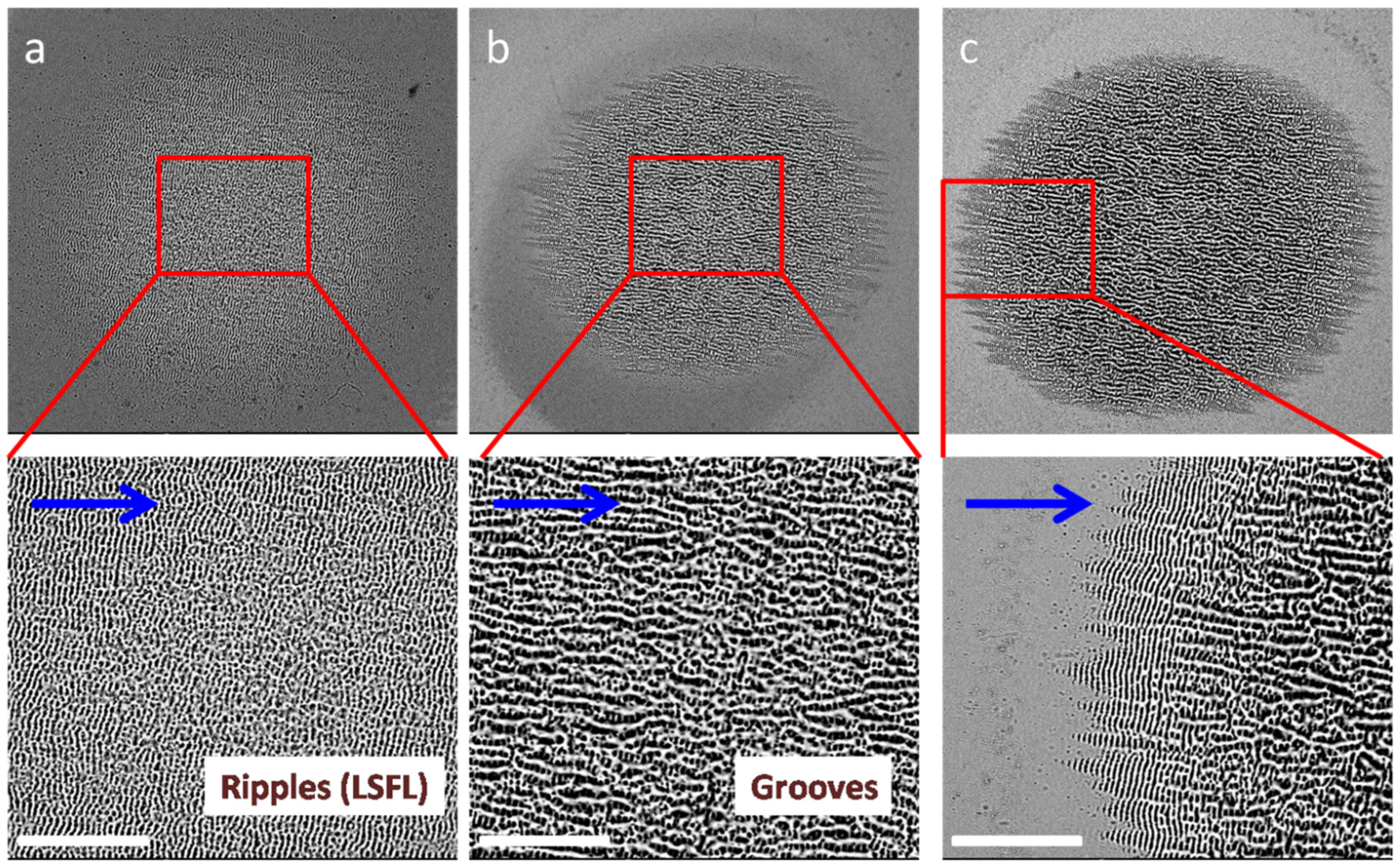
The ablation of GaAs with a linearly polarized Gaussian beam (532 nm, 30 ps) was carried out using different F and numbers of shots (N) in the same position. The most suitable conditions for creating LSFL along the whole area of irradiation were obtained using F = 0.18 J cm−2 and N = 5. Figure 2a shows the almost homogeneous distribution of ripples except for the central part of the beam, where the grooves started to appear (bottom panel of Figure 2a). The direction of the ripples was orthogonal to the polarization of the Gaussian beam, and the spatial period was ΔR = 480 ± 30 nm.
Notice that the optimal number of laser shots is the most important parameter, allowing the ripple formation along the whole area of ablation at the used experimental conditions (N = 5, F = 0.18 J cm−2). The surface morphology depends on the number of shots, while the spatial periods of ripples and grooves remain constant. Meanwhile, the increase in the number of laser shots on the same spot of GaAs at F = 0.18 J cm−2 (from five shots (Figure 2a) to 25 shots (Figure 2c)) drastically changed the morphology of nanoripples. At N = 15, the central area of the ablated surface was entirely filled in with grooves (Figure 2b, bottom panel). Contrary to ripples, grooves showed a characteristic preferential alignment parallel to laser polarization and, hence, orthogonal to ripples. From the center up to a radial distance of ~25 μm, the area became covered by micron-sized quasi-periodic structures with a preferential alignment along the laser polarization. The low-frequency LIPSS were almost entirely replaced by the grooves (ΔG ≈ 1200 nm) in the case of the 25 shots, except for the edges of the ablated area (see bottom panel of Figure 2c). The outer area of the spot shown in the bottom panel of Figure 2c still presents the periodic ripples orthogonal to the laser polarization. An intermediate region between LSFL and grooves represents a mixture of two orthogonal structures rather than rudiments of the grooves superimposed over ripples, as reported in a few previous studies of LIPSS formation on the silicon surface [34,36,41]. Notice that the increase in the F of the heating beam from 0.18 to 0.35 J cm−2 did not change the shape of the nanoripples in the case of five shots in the same place.
There is still no specific explanation for the groove formation. These quasi-periodic surface structures were reported in different semiconductors, like InP, Si, etc., in the case of irradiation using many laser pulses and at high F [36]. In the meantime, given the strong correlation of LIPSS to the polarization of electromagnetic radiation, the formation of ripples and grooves can be used as a probe for the local orientation of the polarization in complex intensity and polarization-shaped laser beams [46].
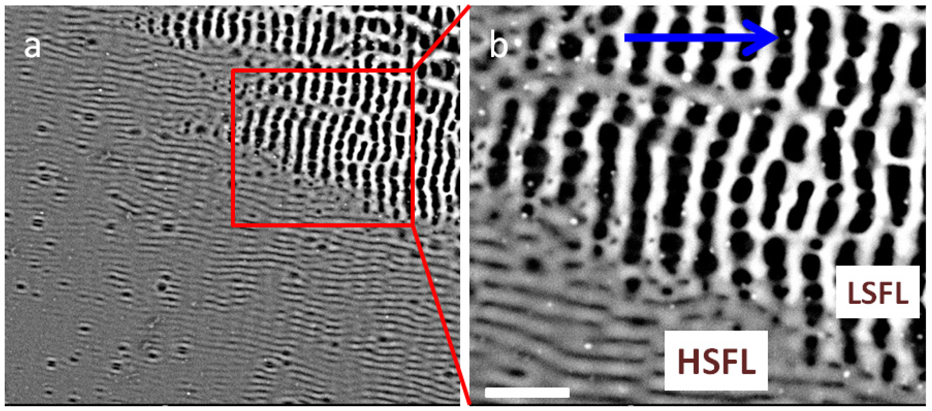
These studies showed that the local laser fluence, which differs from the average F calculated at the equal energy of the laser beam along the whole ablation area, has a decisive influence on the variation of LIPSS. We observed that, depending on its value, two types of ripples (LSFL and HSFL) were generated close to each other in the same material. Transiently changing optical properties caused by a sufficient number of laser-produced electrons promoted to the conduction band cause a transition between the plasmonic LSFL (perpendicular to the polarization) and HSFL (parallel to the polarization) [18,43]. Figure 3a shows the border between LSFL produced at higher local fluence and HSFL produced at the very edge of the ablated spot (F = 0.18 J cm−2, N = 30). The spatial period of HSFL was 270 ± 30 nm, while the distance between LSFL was 480 ± 30 nm (see Figure 3b showing the enlarged part of Figure 3a).

3.2. Radially and Azimuthally Polarized Beams

The application of vector beams changed the dimension of ripples from 1D to 2D. The radial distribution of polarization and the annular form of the laser beam resulted in drastic changes in the morphology of nanostructures. Figure 4, Figure 5 and Figure 6d shown below were obtained using a fixed number of shots (N = 5) on the same spot on the target surface. The spatial shape of the ablated area was changed from the Gaussian distribution to a doughnut-like shape (Figure 4a). The fluence of the used annular beam in the case of the radial polarization was ~0.22 J cm−2. One can see the unablated area of the surface of GaAs at the center of the annular beam. The visible diameter of the outer ablated area produced by the annular beam was ~160 μm. The white arrows show the directions of polarization of the used radially polarized annular beam. The enlarged part of this figure (Figure 4b) allowed for observing the grooves along almost the whole ring-like region of the ablated surface. The direction of the grooves was parallel to the polarization of the laser beam in each specific position of the ablated area.
The fluency of this vector radiation was relatively strong in the central parts of the annular ablated area. This obstacle resulted in the disappearance of the ring-like ripples produced in this area. The only places where those ripples remained were the outer and inner edges of the annular ablated area. Figure 4c,d shows the enlarged parts of Figure 4b. They correspond to the inner and outer areas of the doughnut-like pattern of the ablated part. The ring-like ripples were perpendicular to the polarizations marked by the white arrows. The interesting peculiarity of Figure 4c,d is the presence of rings of ripples at the inner and outer parts of the ablated area, as well as beneath the grooves orthogonally directed with respect to the ripples. Those grooves had a chaotic shape, with the spatial period varying between 800 and 1400 nm. The spatial period of the grooves increased with the growth of distance from the center of the ablated area. Then, additional grooves appeared at larger distances from the center of the ablation area. Meanwhile, the spatial period between the ring-like ripples along the whole ablation area, i.e., in the inner, central, and outer parts of annular ablation, remained the same (ΔR = 470 ± 30 μm).
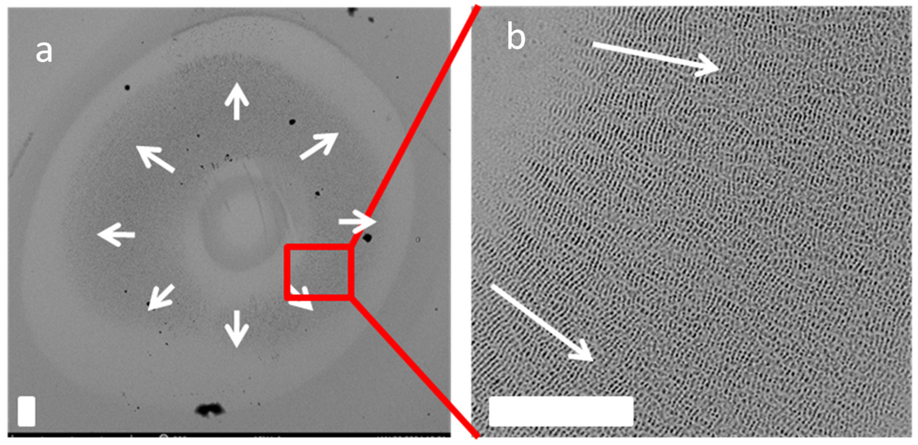
In the case of the smaller fluence of the radially polarized laser beam (F = 0.18 J cm−2), the annular shape of the ablation area (Figure 5a) appeared similar to the previous case (Figure 4). We used the smaller fluence of laser radiation to exclude the appearance of grooves. In that case, only LSFL filled in the ablation area. The enlarged part of the ablated area is shown in Figure 5b. One can see that the whole area of ablation was filled with rings attributed to LSFL. The spatial period between ring-like ripples (ΔR = 460 ± 30 mm) became constant along the whole area of ablation.
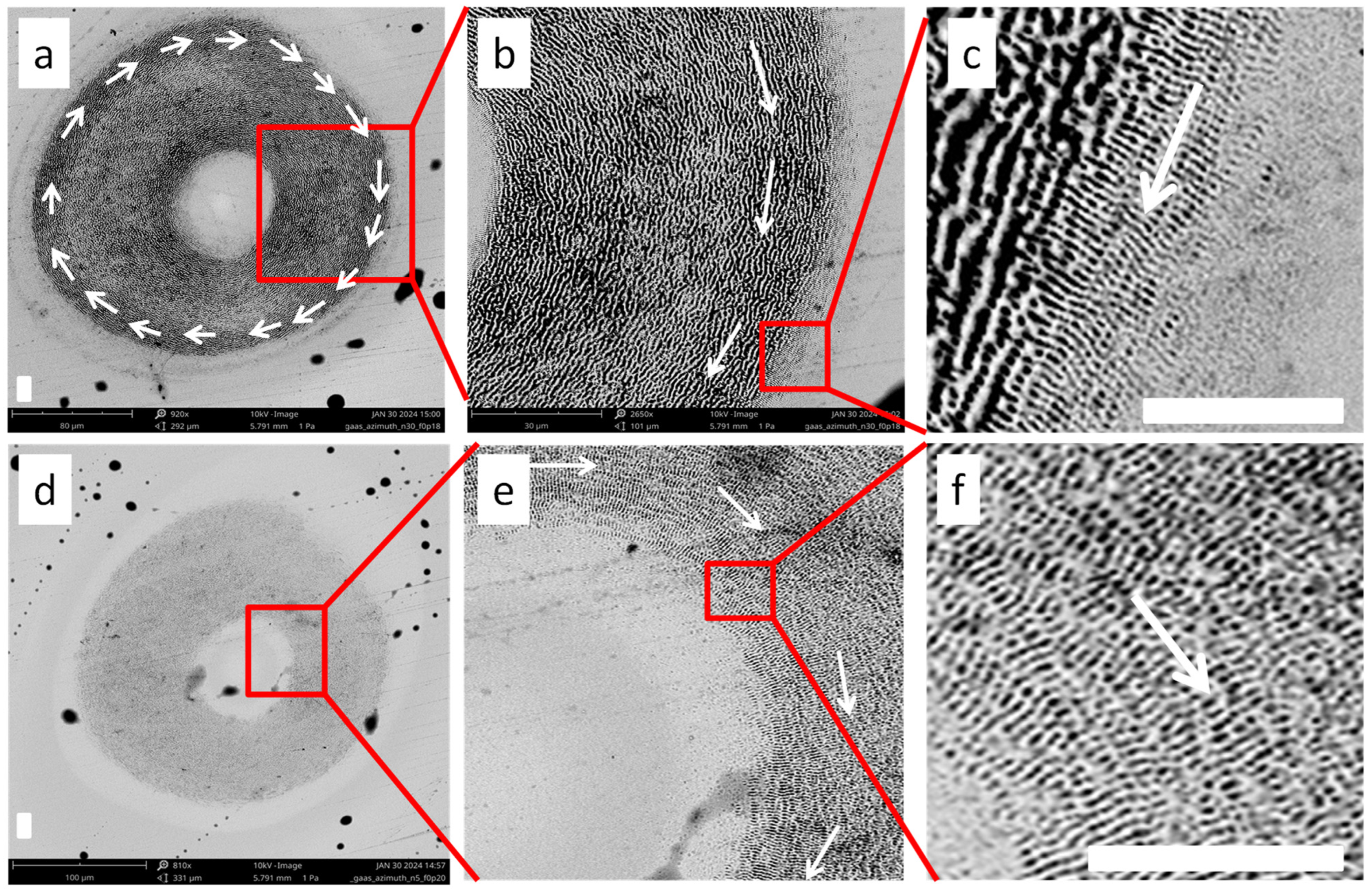
Similar studies using an azimuthally polarized 532 nm beam have demonstrated the pattern of ripples and groove formation at orthogonal directions with regard to the above-studied case using the radially polarized beam. Figure 6a presents the SEM image of the ablated area of GaAs in the case of an azimuthally polarized beam. The white arrows show the polarization structure of the used annular beam. The radiation characteristics used in that case were as follows: wavelength 532 nm, pulse duration 30 ps, N = 20, and F = 0.22 J cm−2. The enlarged part of the ablated area is shown in the Figure 6b. One can see that the annular pattern of the ablated area is filled in with grooves representing the ring-like structure and following the direction of polarization. Further enlargement of the SEM of the ablated area is shown in Figure 6c, representing part of the outer area of the ablated sample. One can see the relatively sharp border between the grooves and the LSFL. The latter structure represented the ripples directed from the center of the ablated doughnut-like pattern. The ripples were orthogonal to the direction of polarization along the whole area of the outer part of the ablated area. The spatial period of grooves in that case was ~1.2 μm, while the spatial period of ripples was ~450 nm. No LSFL remained in the area filled in with grooves, contrary to the case of the application of the radially polarized beam shown in Figure 4c, which was obtained using the same fluence of the beam.
The SEM of the ablated area using a smaller number of shots of an azimuthally polarized beam (N = 5, F = 0.22 J cm−2) is shown in Figure 6d. The enlargement of the inner part of the ablated ring shows the regular LSFL without the presence of the grooves (Figure 6e). The directions of regular ripples (ΔR = 460 ± 20 nm) were, as usual, perpendicular to the polarization of the beam at all parts of the ablated area. The enlarged image of the red square marked in Figure 6e is shown in Figure 6f.
A sharp spatial transition between the external rippled area and the central grooved region suggests the existence of a threshold for the transition from ripples to grooves at a higher number of shots in the same place (Figure 6c). Notice that in the case of the Gaussian beam (bottom panel of Figure 2c) and the radially polarized beam (Figure 4c,d), we observed a less pronounced border between the ripples and grooves. This difference can be attributed to the variation in the number of shots at the same place. Thus, the number of shots becomes the main factor allowing the fabrication of diverse, complex surface patterns when the orthogonal nano- and microstructured patterns coexist with each other. Figure 6c,d represents the “ripple + microstructure” patterns at the GaAs surface induced by different vector light fields. At a small number of shots (in the present experimental conditions, N = 5), they exhibit the equal-interval concentric ring structure of ripples (in the case of a radially polarized field) and the radial structure of ripples (in the case of an azimuthally polarized field).

3.3. Joint Influence of Azimuthal and Radial Polarizations on Nanostructure Formation

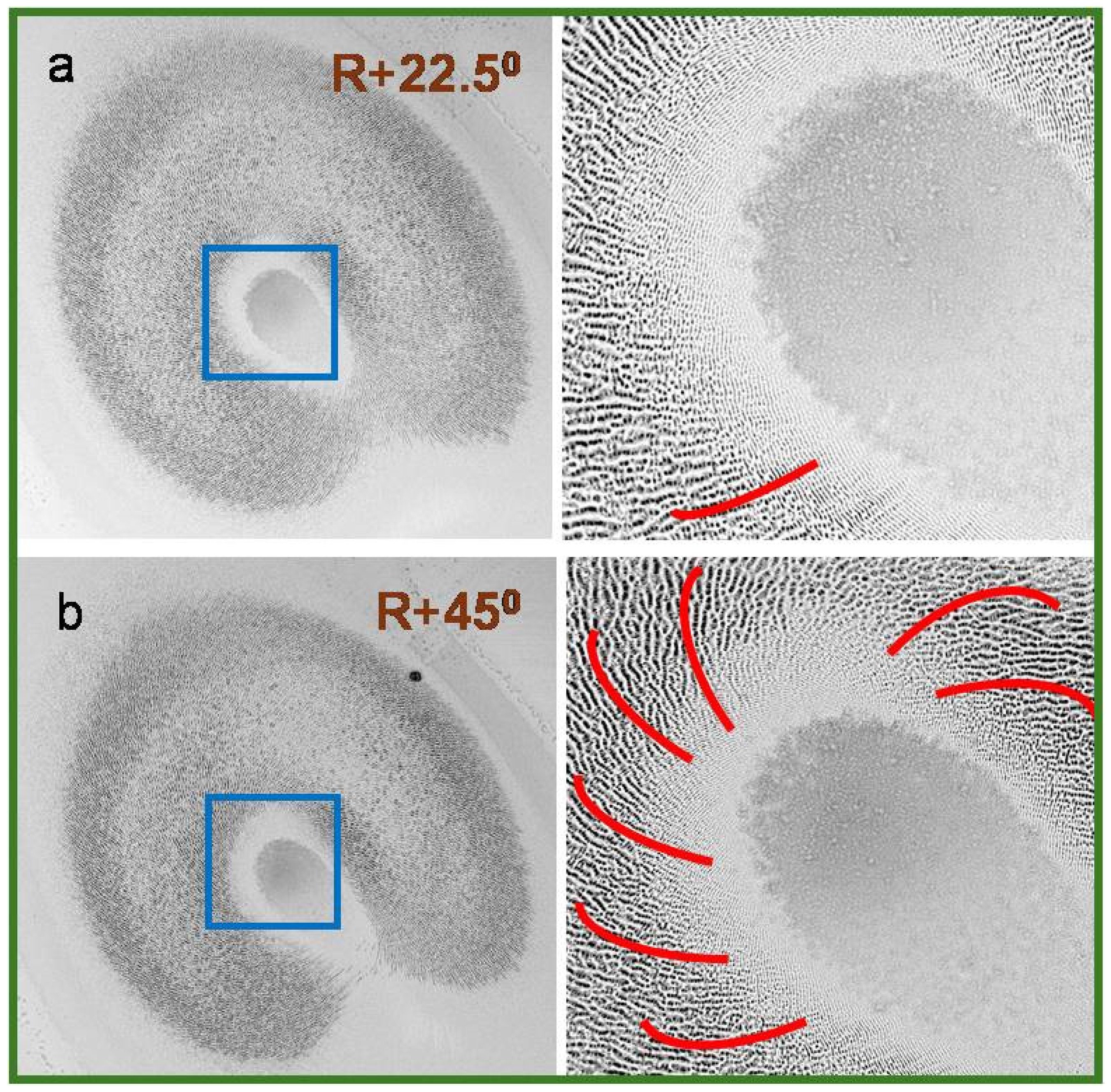
Below, we show the case when two fields coexist in the same set of ablation experiments. This condition was implemented with the gradual rotation of the S-waveplate between two positions, allowing for the formation of an intermediate state of radial and azimuthal polarization. Figure 7 shows the images of the focused radiation (a, d) and SEM patterns of the linearly polarized Gaussian laser-induced ablation (b) and radial polarization-induced ablation (e), as well as the enlarged images of SEM patterns (c, f), respectively. As in all cases shown in the above-reported studies (Figure 2, Figure 3, Figure 4, Figure 5 and Figure 6), the directions of ripples and grooves are perpendicular and parallel to the polarizations of the beam, respectively (see also the enlarged images of the parts of ablation areas shown in Figure 7c,f). During these experiments, the fluence on the surface was 0.12 J cm−2, i.e., it was less than in the cases presented in Figure 4 and Figure 6. At the same time, the number of shots was increased to 30.
Once we rotated the S-waveplate out of the position corresponding to the formation of a radially polarized beam, the pattern of ripples and grooves was modified by the inclination of those nano- and microstructures. The marked angles of rotation of the S-waveplate were measured with reference to the marker on the S-waveplate corresponding to the radial polarization. In the case of the rotation of the S-waveplate at 22.5°, the image of the ablation area remained the same as in the case of purely radial polarization (compare Figure 7e and the left panel of Figure 8a). At these conditions, we observed a small inclination of the grooves and ripples (right panel of Figure 8a). Further rotation of the S-waveplate at an angle of 45° with regard to the position corresponding to pure radial polarization led to a stronger leaning of the grooves (right panel of Figure 8b) and ripples (barely seen in this figure), resulting in deviation from the shapes of nano- and microstructures analyzed in previous subsections. Red-colored curves show the polarization of the laser beam and the directions of the grooves in this case.
An additional peculiarity, in that case, is a modification of the spatial shape of the ablated area compared with the case of the pure radial polarization of the heating beam (compare the left panel of Figure 8b and Figure 7e). Specifically, the formation of an intermediate state of radial and azimuthal polarizations leads to a significant difference in the shape and inclination of the ripples and grooves on the ablated surface.
Since the shape of ripples and grooves strongly depends on the incoming beam polarization, one of the important advantages of using vector beams in surface modification is the possibility of generating 2D structures using the variable states of polarization. In general, radial and azimuthal states are the two polarizations that can be obtained by either rotating the incoming linear polarization from horizontal to vertical prior to entering the S-waveplate or by rotating the S-waveplate by 90° at a fixed linear polarization of the Gaussian beam. Correspondingly, the spiral or intermediate states of polarization can be obtained while varying the input polarization between these two states. Moreover, other numerous kinds of complex states of polarization can be achieved by using the additional optical elements in the beam path, like wave plates (λ/2 and λ/4), before and/or after the S-waveplate.
The S-waveplate orientation to different angles is responsible for the polarization variation, causing a change in the intensity distribution of the resultant spatial profile formed at the focal plane, as illustrated in Figure 2a and Figure 8b. Notice that the intensity profile of the output beams produced by the S-waveplate at these conditions has some discontinuity due to the Gaussian input beam size, which cannot fully cover the active area of the S-waveplate, denoted as aperture size. The magnitude of this discontinuity varies depending on the orientation of the S-waveplate, as illustrated in Figure 8a,b. In the case of a radially polarized vector beam (i.e., at pure radial polarization), the intensity profile around the phase singularity or central region was found to be a clear doughnut structure (Figure 4a and Figure 7d).
The S-waveplate rotation by 22.5° and 45° with regard to radial polarization orientation resulted in laser-induced surface structures attributed to different inclined polarizations. In these cases, the grooves formed around the phase singularity or nonablated center take an orientation corresponding to the inclined polarization of the beam (right panels of Figure 8). The SEM micrographs at higher magnification shown in Figure 8a,b were included to better visualize the role of leaned polarization on the surface morphology modification and the corresponding inclination of ripples and grooves. When the S-waveplate rotated by 90° concerning radial polarization orientation, a vector beam with azimuthal polarization formed a laser-induced surface structure on the sample at the focal plane similar to the one shown in Figure 6.

4. Discussion

The interest in nanoripples is defined by potential applications in building microfluidic channels, changing the color of materials, modifying local electrical properties, building sub-diffraction-limit optical diffraction gratings, detecting materials with increased sensitivity using surface-enhanced Raman scattering, bio-sensing, water contamination monitoring, detecting organic molecules, etc. [5,6,7,8]. Correspondingly, the determination of the conditions under which the shape of nano- or microrelief can be modified through the modulation of the phase and polarization of the laser pulse is of the utmost importance for clarifying the best options in this way. The reported study demonstrates the modulation and spatial shapes of the ripples and grooves by applying the S-waveplate at different positions with regard to the linear polarization of the Gaussian beam.
GaAs is an example of a narrow bandgap semiconducting surface, resulting in wider types of nano- and microstructures formed during the illumination of the laser radiation possessing specific polarization properties. In these LIPSS studies, we analyzed the ripples on the GaAs surface with a regular quasi-periodic structure, with a spatial period (470 ± 30 nm) slightly less than the laser wavelength (532 nm) and a preferential orientation along the normal to the incident laser polarization. Additionally, the relatively larger (1300 nm) quasi-periodic structures called grooves, whose preferential alignment is in the direction of the laser polarization, played a significant role in the modulation of the surface of GaAs. These structures are formed in the high-F area or at a larger number of shots.
Figure 3 shows the joint appearance of HSFL and LSFL on the GaAs surface in the case of a linearly polarized Gaussian beam. HSFL and LSFL, with the ratios of their spatial periods in the range of 0.1–0.5, were frequently reported in the past using different materials. Notice that the formation of HSFL using a Gaussian beam was not the goal of the present study. We observed them alongside the LSFL. HSFL + LSFL and 2D-LIPSS are two different morphological formations produced using Gaussian and vector laser beams, respectively. The former structure on the GaAs surface was reported in [47], where the alignment of morphology during high spatial frequency periodic structure formation in GaAs was carried out. Their interpretation of the formation of HSFL was based on the morphological evolution from self-interstitial diffusion, driven by stress relaxation, to the surface producing 1–2 nm tall islands. They also provided the calculation of excited electron concentration combined with a Drude–Lorentz model of the excited GaAs dielectric function to determine the conditions for SPP coupling at HSFL formation.
Different materials were analyzed during a demonstration of ripple formation. The high- and low-spatial frequency LIPSS on the molybdenum disulfide was reported in [48]. They have shown that, depending on the laser power, it is possible to choose between the formations of only HSFL or a combination of two groups of nanoripples (HSFL and LSFL) in the case of the linearly polarized Gaussian pulses. In [49], a special type of femtosecond laser-induced nanoripples comprising LSFL and HSFL was fabricated simultaneously on a stainless-steel surface. These LSFL and embedded HSFL were oriented orthogonally to each other. We did not study the phenomenon of high- and low-frequency ripple formation under irradiation of the linearly polarized beam. What we showed is the overlap of the radially directed nanoripples and annually directed grooves in the case of the azimuthally polarized annular laser beam (Figure 6). We also demonstrated the overlap of the annually directed nanoripples and radially directed grooves using the radially polarized annular laser beam (Figure 4).
Our studies showed a preferential formation of large structures (grooves) on the surface of GaAs with the growth of the number of pulses at relatively low fluencies of laser pulses. Those grooves overlap the periodic ripple pattern. The ripples can still be seen in this case under the grooves aligned along the laser polarization. At a large number of pulses on the spot, the growing grooves cancel the presence of LSFL, which remains only at the edges of ablation, particularly at the internal and external edges of the annular ablation area. It is worth mentioning that the geometry of these two groups of structures can be precisely controlled by choosing the proper number of heating pulses on the same spot or by tuning the fluence of the laser pulse.
We showed that the radial and annular nanoripples appeared on the surface of GaAs under the ablation using doughnut-like beams possessing azimuthal and radial polarizations, respectively. The joint overlap of the microgrooves and the nanoripples formed by linear, azimuthal, and radial polarizations was analyzed at different numbers of interacting shots and fluencies of the laser pulses. The orthogonally directed grooves (ΔG = 1.3–1.5 μm) dominated over the regular low-frequency LIPSS (ΔR = 470 nm) with the growth of laser fluence. The preferential emergence of either LIPSS or grooves at different numbers of shots was analyzed. Our aim was to show the appearance of different 2D ripples and grooves on the surface of the GaAs wafer.
We demonstrated different 2D ripples and grooves on the surface of the GaAs wafer in the case of the fixed target. The optimization of this process allows further steps in the formation of the extended 2D rippling of the surfaces. Notice that the overlap of moving shots in that case may cause the erasing of the radial or annular ripples and grooves. In the present work, we resolved the first task—a demonstration of the optimal conditions for ring-like and radial ripple formation at the fixed position of the target and laser spot. Notice that the formation of the line shape of these ripples and grooves cannot be considered as a final task since it will allow the formation of the ~100 micron thick lines, which do not provide the realistic picture for the practical applications until the development of the technique of the filling in the whole area of the semiconductor wafer. Thus, the single spot exposure does not give information about the technical use in the same way as the line exposure. However, it provides the expertise on how to achieve the formation of 2D ripples during the fixed positions of the target and beam. Correspondingly, without this step of studies, allowing for the optimization of the parameters of laser radiation, it would be difficult to optimize the formation of nano- and microstructured 2D patterns during the movement of the ablating beam or target.

5. Conclusions

We studied the formation of linear, radial, and annular ripples on the surface of GaAs using the vector beams produced during the propagation of the laser radiation with the S-waveplate, as well as Gaussian linearly polarized beams. The formation of regular linear ripples with a spatial period slightly less than the wavelength of laser radiation was optimized by the number of shots and the fluence of the 30 ps, 532 nm Gaussian beam. The orthogonally directed HSFL with a spatial period that is twice smaller than that of LSFL was observed at smaller fluencies of laser pulses. Radial and annular nanoripples appeared on the surface of GaAs under the ablation using doughnut-like beams possessing azimuthal and radial polarizations, respectively. The joint overlap of the microgrooves and the nanoripples formed using linear, azimuthal, and radial polarizations was analyzed at different numbers of interacting shots and fluencies of the laser pulses. In all the above cases, the grooves (ΔG = 1.3–1.5 μm) dominated over the regular low-frequency LIPSSs (ΔR = 470 nm). The preferential emergence of either LIPSSs or grooves at different numbers of shots was analyzed. To better visualize the role of leaned polarization in the surface morphology modification and corresponding inclination of ripples and grooves, we tuned the position of the installed S-waveplate between the generation of azimuthal and radial polarizations.

Author Contributions

Conceptualization, R.A.G.; investigation, K.K., V.V.K., A.N.K.R. and A.S.; methodology, R.A.G.; supervision, R.A.G.; writing—original draft, R.A.G.; writing—review and editing, A.N.K.R., A.S. and R.A.G. All authors have read and agreed to the published version of the manuscript.

Funding

European Regional Development Fund (1.1.1.5/19/A/003), State Task for Universities (FZGU-2023-0007), Latvian Science Council (Lzp-2023/1-0199).

Institutional Review Board Statement

Not applicable.

Informed Consent Statement

Not applicable.

Data Availability Statement

The data that support the findings of this study are available on request from the corresponding author.

Acknowledgments

A. Sarakovskis acknowledges the European Union’s Horizon 2020 Framework Program H2020-WIDESPREAD-01-2016-2017-TeamingPhase2 under grant agreement No. 739508, project CAMART2.

Conflicts of Interest

The authors declare no conflicts of interest.

References

  1. Cai, W.; Libertun, A.R.; Piestun, R. Polarization selective computer-generated holograms realized in glass by femtosecond laser induced nanogratings. Opt. Express 2006, 14, 3785–3791. [Google Scholar] [CrossRef] [PubMed]
  2. Shimotsuma, Y.; Sakakura, M.; Kazansky, P.G.; Beresna, M.; Qiu, J.; Miura, K.; Hirao, K. Ultrafast manipulation of self-assembled form birefringence in glass. Adv. Mater. 2010, 22, 4039–4043. [Google Scholar] [CrossRef] [PubMed]
  3. Beresna, M.; Gecevičius, M.; Kazansky, P.G. Polarization sensitive elements fabricated by femtosecond laser nanostructuring of glass. Opt. Mater. Express 2011, 1, 783–794. [Google Scholar] [CrossRef]
  4. Jin, J.; Allegre, O.J.; Perrie, W.; Abrams, K.; Ouyang, J.; Fearon, E.; Edwardson, S.P.; Dearden, G. Dynamic modulation of spatially structured polarization fields for real-time control of ultrafast laser-material interactions. Opt. Express 2013, 21, 25333–25343. [Google Scholar] [CrossRef] [PubMed]
  5. Vorobyev, A.Y.; Guo, C. Direct femtosecond laser surface nano/microstructuring and its applications. Laser Phot. Rev. 2013, 7, 385–407. [Google Scholar] [CrossRef]
  6. Bonse, J.; Koter, R.; Hartelt, M.; Spaltmann, D.; Pentzien, S.; Höhm, S.; Rosenfeld, A.; Krüger, J. Femtosecond laser-induced periodic surface structures on steel and titanium alloy for tribological applications. Appl. Phys. A Mater. Sci. Process. 2014, 117, 103–110. [Google Scholar] [CrossRef]
  7. Gu, M.; Li, X.P.; Cao, Y.Y. Optical storage arrays: A perspective for future big data storage. Light Sci. Appl. 2014, 3, e177. [Google Scholar] [CrossRef]
  8. Lei, Y.; Wang, H.; Shayeganrad, G.; Kazansky, P.G. Ultrafast laser nanostructuring in transparent materials for beam shaping and data storage. Opt. Mater. Express 2022, 12, 3327–3355. [Google Scholar] [CrossRef]
  9. Alnaser, A.S.; Khan, S.A.; Ganeev, R.A.; Stratakis, E. Recent advances in femtosecond laser-induced surface structuring for oil–water separation. Appl. Sci. 2019, 9, 1554. [Google Scholar] [CrossRef]
  10. Khan, S.A.; Ialyshev, V.; Kim, V.V.; Iqbal, M.; Al Harmi, H.; Boltaev, G.S.; Ganeev, R.A.; Alnaser, A.S. Expedited transition in the wettability response of metal meshes structured by femtosecond laser pulses for oil-water separation. Front. Chem. 2020, 8, 768. [Google Scholar] [CrossRef]
  11. Iqbal, M.; Ialyshev, V.; Kim, V.V.; Boltaev, G.S.; Ivanov, D.; Rethfeld, B.; Ganeev, R.A.; Alnaser, A.S. Simultaneous manipulation of the optical and wettability properties of metal surfaces using 150 kHz femtosecond fiber laser. Appl. Sci. 2020, 10, 6207. [Google Scholar] [CrossRef]
  12. Rahimian, M.G.; Jain, A.; Larocque, H.; Corkum, P.B.; Karimi, E.; Bhardwaj, V.R. Spatially controlled nanostructuring of silicon with femtosecond vortex pulses. Sci. Rep. 2020, 10, 12643. [Google Scholar] [CrossRef]
  13. Boltaev, G.S.; Alghabra, M.S.; Iqbal, M.; Ganeev, R.A.; Alnaser, A.S. Creation of azimuthally and radially directed laser-induced periodic structures on large tantalum surface. J. Phys. D 2021, 54, 185109. [Google Scholar] [CrossRef]
  14. Li, Z.; Allegre, O.; Li, L. Realising high aspect ratio 10 nm feature size in laser materials processing in air at 800 nm wavelength in the far-field by creating a high purity longitudinal light field at focus. Light Sci. Appl. 2022, 11, 339. [Google Scholar] [CrossRef]
  15. Zhang, Y.C.; Jiang, Q.L.; Long, M.Q.; Han, R.Z.; Cao, K.Q.; Zhang, S.; Feng, D.; Jia, T.; Sun, Z.; Qiu, J.; et al. Femtosecond laser-induced periodic structures: Mechanisms, techniques, and applications. Opto-Electron. Sci. 2022, 1, 220005. [Google Scholar] [CrossRef]
  16. Sun, H.; Li, J.; Liu, M.; Yang, D.; Li, F. A review of effects of femtosecond laser parameters on metal surface properties. Coatings 2022, 12, 1596. [Google Scholar] [CrossRef]
  17. Maalouf, M.; Abou Khalil, A.; Di Maio, Y.; Papa, S.; Sedao, X.; Dalix, E.; Peyroche, S.; Guignandon, A.; Dumas, V. Polarization of femtosecond laser for titanium alloy nanopatterning influences osteoblastic differentiation. Nanomaterials 2022, 12, 1619. [Google Scholar] [CrossRef]
  18. Rajendran, R.; Krishnadev, E.R.; Anoop, K.K. Direct femtosecond laser processing for generating high spatial frequency LIPSS (HSFL) on borosilicate glasses with large-area coverage. Photonics 2023, 10, 793. [Google Scholar] [CrossRef]
  19. Sipe, J.E.; Young, J.F.; Preston, J.S.; Van Driel, H.M. Laser-induced periodic surface structure. I. Theory. Phys Rev. B 1983, 27, 1141–1154. [Google Scholar] [CrossRef]
  20. Bonse, J.; Munz, M.; Sturm, H. Structure formation on the surface of indium phosphide irradiated by femtosecond laser pulses. J. Appl. Phys. 2005, 97, 013538. [Google Scholar] [CrossRef]
  21. Jia, T.Q.; Chen, H.X.; Huang, M.; Zhao, F.L.; Qiu, J.R.; Li, R.X.; Xu, Z.Z.; He, H.K.; Zhang, J.; Kuroda, H. Formation of nanogratings on the surface of a ZnSe crystal irradiated by femtosecond laser pulses. Phys. Rev. B 2005, 72, 125429. [Google Scholar] [CrossRef]
  22. Huang, M.; Zhao, F.L.; Cheng, Y.; Xu, N.; Xu, Z.Z. Origin of laser-induced near-subwavelength ripples: Interference between surface plasmons and incident laser. ACS Nano 2009, 3, 4062–4070. [Google Scholar] [CrossRef]
  23. Cheng, K.; Liu, J.K.; Cao, K.Q.; Chen, L.; Zhang, Y.C.; Jiang, Q.; Feng, D.; Zhang, S.; Sun, Z.; Jia, T.Q. Ultrafast dynamics of single-pulse femtosecond laser-induced periodic ripples on the surface of a gold film. Phys. Rev. B 2018, 98, 184106. [Google Scholar] [CrossRef]
  24. Volkov, S.N.; Kaplan, A.E.; Miyazaki, K. Evanescent field at nanocorrugated dielectric surface. Appl. Phys. Lett. 2009, 94, 041104. [Google Scholar] [CrossRef]
  25. Reif, J.; Varlamova, O.; Uhlig, S.; Varlamov, S.; Bestehorn, M. On the physics of self-organized nanostructure formation upon femtosecond laser ablation. Appl. Phys. A 2014, 117, 179–184. [Google Scholar] [CrossRef]
  26. Tsibidis, G.D.; Fotakis, C.; Stratakis, E. From ripples to spikes: A hydrodynamical mechanism to interpret femtosecond laser-induced self-assembled structures. Phys. Rev. B 2015, 92, 041405. [Google Scholar] [CrossRef]
  27. Dong, Y.Y.; Molian, P. Coulomb explosion-induced formation of highly oriented nanoparticles on thin films of 3C-SiC by the femtosecond pulsed laser. Appl. Phys. Lett. 2004, 84, 10–12. [Google Scholar] [CrossRef]
  28. Huang, M.; Zhao, F.L.; Cheng, Y.; Xu, N.; Xu, Z.Z. Mechanisms of ultrafast laser-induced deep-subwavelength gratings on graphite and diamond. Phys. Rev. B 2009, 79, 125436. [Google Scholar] [CrossRef]
  29. Maurer, C.; Jesacher, A.; Fürhapter, S.; Bernet, S.; Ritsch-Marte, M. Tailoring of arbitrary optical vector beams. New J. Phys. 2007, 3, 78. [Google Scholar] [CrossRef]
  30. Zhan, Q. Cylindrical vector beams: From mathematical concepts to applications. Adv. Opt. Photonics 2009, 1, 1–57. [Google Scholar] [CrossRef]
  31. Fickler, R.; Lapkiewicz, R.; Ramelow, S.; Zeilinger, A. Quantum entanglement of complex photon polarization patterns in vector beams. Phys. Rev. A 2014, 89, 060301. [Google Scholar] [CrossRef]
  32. Cardano, F.; Karimi, E.; Slussarenko, S.; Marrucci, L.; de Lisio, C.; Santamato, E. Polarization pattern of vector vortex beams generated by q-plate with different topological charges. Appl. Opt. 2012, 51, C1–C6. [Google Scholar] [CrossRef]
  33. Jia, J.; Baba, M.; Suzuki, M.; Ganeev, R.A.; Kuroda, H.; Qiu, J.; Wang, X.; Li, R.; Xu, Z. Fabrication of two-dimensional periodic nanostructures by two-beam interference of femtosecond pulses. Opt. Express 2008, 16, 1874–1878. [Google Scholar] [CrossRef]
  34. Tomita, T.; Kumai, R.; Matsuo, S.; Hashimoto, S.; Yamaguchi, M. Cross-sectional morphological profiles of ripples on Si, SiC, and HOPG. Appl. Phys. A 2009, 97, 271–276. [Google Scholar] [CrossRef]
  35. Crawford, T.H.R.; Botton, G.A.; Haugen, H.K. Crystalline orientation effects on conical structure formation in femtosecond laser irradiation of silicon and germanium. Appl. Surf. Sci. 2010, 256, 1749–1755. [Google Scholar] [CrossRef]
  36. Lou, K.; Qian, S.-X.; Wang, X.-L.; Li, Y.; Gu, B.; Tu, C.; Wang, H.-T. Two-dimensional microstructures induced by femtosecond vector light fields on silicon. Opt. Express 2012, 20, 120–127. [Google Scholar] [CrossRef]
  37. Messaddeq, S.H.; Vallée, R.; Soucy, P.; Bernier, M.; El-Amraoui, M.; Messaddeq, Y. Self-organized periodic structures on Ge-S based chalcogenide glass induced by femtosecond laser irradiation. Opt. Express 2012, 20, 29882–29889. [Google Scholar] [CrossRef]
  38. Sanz, M.; Rebollar, E.; Ganeev, R.A.; Castillejo, M. Nanosecond laser-induced periodic surface structures on wide band-gap semiconductors. Appl. Surf. Sci. 2013, 278, 325–329. [Google Scholar] [CrossRef]
  39. Ganeev, R.A.; Lei, D.Y.; Hutchison, C.; Witting, T.; Frank, F.; Okell, W.A.; Roschuk, T.R.; Maier, S.A.; Tisch, J.W.G.; Marangos, J.P. Extended homogeneous nanoripple formation during interaction of high-intensity few-cycle pulses with a moving silicon wafer. Appl. Phys. A 2013, 112, 457–462. [Google Scholar] [CrossRef]
  40. Skoulas, E.; Manousaki, A.; Fotakis, C.; Stratakis, E. Biomimetic surface structuring using cylindrical vector femtosecond laser beams. Sci. Rep. 2017, 7, 45114. [Google Scholar] [CrossRef]
  41. Chakravarty, U.; Ganeev, R.A.; Naik, P.A.; Chakera, J.A.; Babu, M.; Gupta, P.D. Nano-ripple formation on different band-gap semiconductor surfaces using femtosecond pulses. J. Appl. Phys. 2011, 109, 084347. [Google Scholar] [CrossRef]
  42. Füle, M.; Gárdián, A.; Budai, J.; Tóth, Z. Comparative study of the surface nanostructure formation on different surfaces generated by low number of fs laser pulses. J. Laser Micro Nanoeng. 2015, 10, 74–80. [Google Scholar] [CrossRef]
  43. Abere, M.J.; Torralva, B.; Yalisove, S.M. Periodic surface structure bifurcation induced by ultrafast laser generated point defect diffusion in GaAs. Appl. Phys. Lett. 2016, 108, 153110. [Google Scholar] [CrossRef]
  44. Apostolopoulos, G.; Herfort, J.; Däweritz, L.; Ploog, K.H.; Luysberg, M. Reentrant mound formation in GaAs(001) homoepitaxy observed by ex situ atomic force microscopy. Phys. Rev. Lett. 2000, 84, 3358–3361. [Google Scholar] [CrossRef] [PubMed]
  45. Ballestad, A.; Ruck, B.J.; Schmid, J.H.; Adamcyk, M.; Nodwell, E.; Nicoll, C.; Tiedje, T. Surface morphology of GaAs during molecular beam epitaxy growth: Comparison of experimental data with simulations based on continuum growth equations. Phys. Rev. B 2002, 65, 205302. [Google Scholar] [CrossRef]
  46. Nivas, J.J.J.; He, S.; Rubano, A.; Vecchione, A.; Paparo, D.; Marrucci, L.; Bruzzese, R.; Amoruso, S. Direct femtosecond laser surface structuring with optical vortex beams generated by a q-plate. Sci. Rep. 2015, 5, 17929. [Google Scholar] [CrossRef] [PubMed]
  47. Abere, M.J.; Yalisove, S.M.; Torralva, B. Alignment of morphology during high spatial frequency periodic structure formation in GaAs. J. Appl. Phys. 2019, 126, 143102. [Google Scholar] [CrossRef]
  48. Becher, M.J.M.J.; Jagosz, J.; Bock, C.; Ostendorf, A.; Gurevich, E.L. Formation of low- and high-spatial frequency laser-induced periodic surface structures (LIPSSs) in ALD-deposited MoS2. Front. Nanotechnol. 2023, 5, 1227025. [Google Scholar] [CrossRef]
  49. Abu Taher, M.; Chaudhary, N.; Thirunaukkarasu, K.; Rajput, V.K.; Naraharisetty, S.R.G. Controlled periodicities of ladder-like structures via femtosecond laser of wavelength from 400 nm to 2200 nm. Surf. Interfaces 2022, 28, 101622. [Google Scholar] [CrossRef]
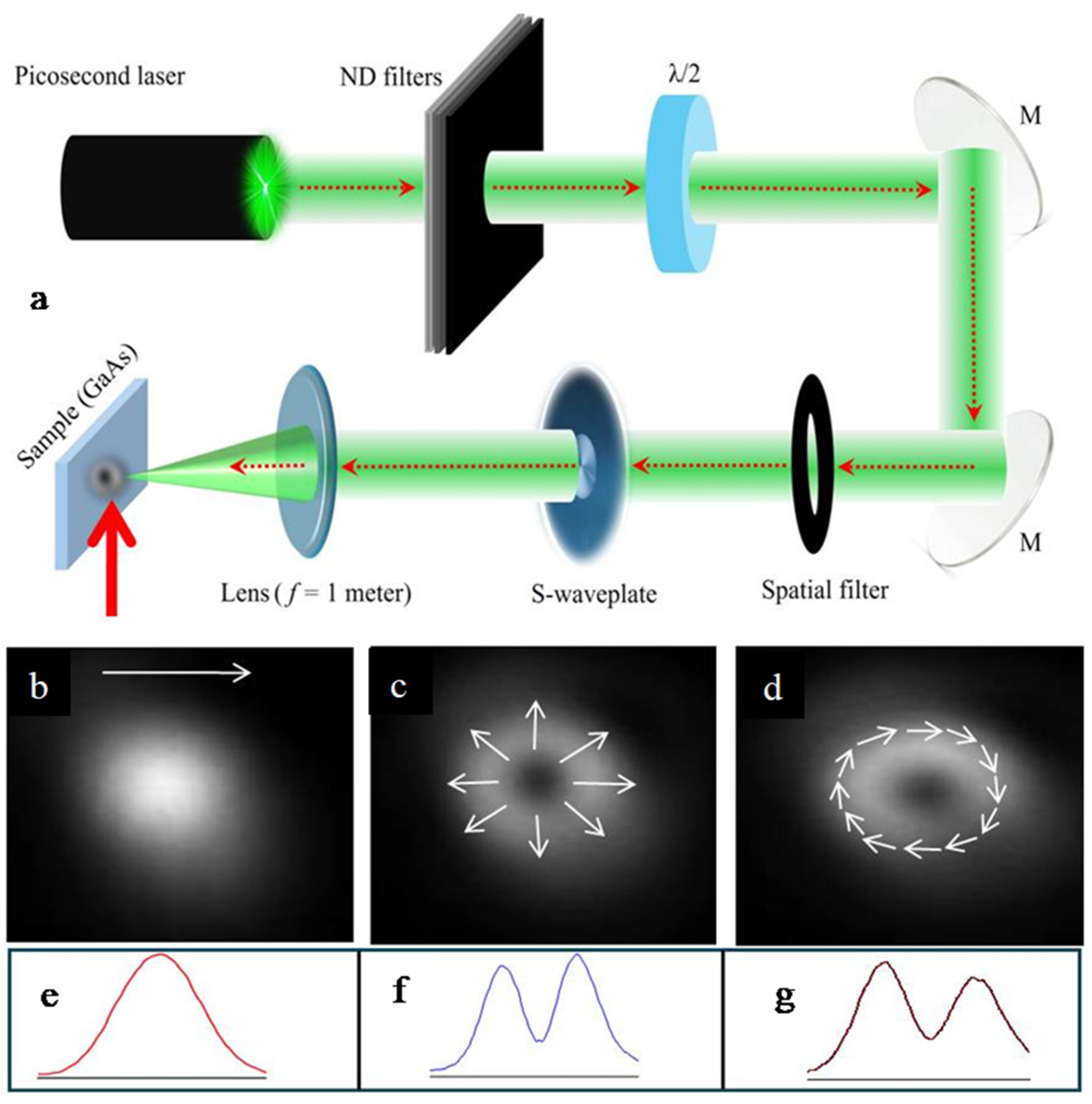
Figure 1. (a) Experimental scheme for LIPSS formation on the surface of GaAs using 532 nm, 30 ps pulses. The bottom insets show the spatial shapes of (b) a linearly polarized Gaussian beam, (c) a radially polarized annular beam, and (d) an azimuthally polarized annular beam and (eg) their corresponding line-outs of spatial distribution. White arrows are the directions of polarization.
Photonics 11 00710 g001
Figure 2. SEM images of ablated GaAs using (a) 5 shots, (b) 15 shots, and (c) 25 shots of 532 nm, 30 ps pulses at the fluence 0.18 J cm−2 on the target surface. The bottom panels of (ac) correspond to the enlarged parts of the corresponding areas marked in red. White lines correspond to 10 μm. Blue arrows show the direction of polarization of the Gaussian beam.
Photonics 11 00710 g002
Figure 3. (a) Appearance of orthogonally directed lines (HSFL) with a smaller spatial period at a larger number of shots (30) on the same place of GaAs. (b) Enlarged part of Figure 3a. The blue arrow shows the direction of polarization of the laser beam. The white line corresponds to 1 μm. The average spatial periods of orthogonal (LSFL and HSFL) ripples were 480 and 270 nm, respectively.
Photonics 11 00710 g003
Figure 4. (a) Spatial shape of the ablated area on the surface of GaAs by the doughnut-like beam with a radial distribution of polarization (white arrows). (b) The enlarged square of Figure 4a shows the part of the ablated ring dominated by the presence of the grooves growing parallel to the polarization. (c) An enlarged part of Figure 4b shows the inner region of the ring. One can see the rings of ripples, followed by the grooves. These ripples remain almost unchanged on the right side of Figure 4c while appearing under the grooves. (d) The enlarged part of Figure 4b shows the outer region of the ring. One can see the LSFL at the smallest fluence of the laser beam, followed by the appearance of the grooves above the rings on the left side of Figure 4d. The white bars correspond to 40 μm (Figure 4a) and 10 μm (Figure 4b–d).
Photonics 11 00710 g004
Figure 5. (a) The shape of the ablated area using the radially polarized beam at F = 0.18 J cm−2 and N = 5. (b) Enlarged part of Figure 5a showing the ring-like LSFL throughout the ablation area. The white bars correspond to 60 μm (Figure 5a) and 10 μm (Figure 5b). While arrows show the direction of polarization of the laser beam.
Photonics 11 00710 g005
Figure 6. (a) SEM image of the whole area of ablation using 20 shots of the azimuthally polarized beam. Almost the whole ablated area was filled in with grooves. (b,c) Enlarged parts of the ablated area and outer border of the ablated area, respectively. The ripples were observed only in the area of the outer border of the ablation. (d) SEM image of the whole area of ablation using 5 shots of the azimuthally polarized beam at the same fluence of heating radiation (F = 0.22 J cm−2) as in the case shown in Figure 6a. (e,f) Enlarged parts of the ablated area and inner border of the ablated area, respectively. LSFL, in that case, dominated along the whole ablated area. The white bars correspond to 80 μm (Figure 6a,d) and 10 μm (Figure 6c,f). While arrows show the direction of polarization of the laser beam.
Photonics 11 00710 g006
Figure 7. (a,d) The intensity profiles of the linearly polarized Gaussian beam and radially polarized beam, respectively. (b,e) The corresponding images of ablated areas. (c,f) The enlarged parts of the red squares are marked in Figure 7b and Figure 7e, respectively. Blue arrows show the direction of polarization of the laser beam.
Photonics 11 00710 g007
Figure 8. Left panels of Figure 8a,b: the images of the ablation areas after laser–matter interaction in the case of the rotation of the S-waveplate by (a) 22.5° and (b) 45° from the position corresponding to the pure radial polarization of the annular beam. The enlarged images of the ablation areas in these two cases are shown in the right panels. Red curved lines show the leaned directions of polarizations at different points of the ablation. The grooves follow these leaned directions of polarization.
Photonics 11 00710 g008
Disclaimer/Publisher’s Note: The statements, opinions and data contained in all publications are solely those of the individual author(s) and contributor(s) and not of MDPI and/or the editor(s). MDPI and/or the editor(s) disclaim responsibility for any injury to people or property resulting from any ideas, methods, instructions or products referred to in the content.