Article

Three-Shot Dual-Frequency Fringe Scheme Based on Spatial Computer-Generated Moiré Fringe

Institute of Optics Electronics, Chinese Academy of Sciences, Chengdu 610207, China
*
Authors to whom correspondence should be addressed.
Photonics 2024, 11(8), 758; https://doi.org/10.3390/photonics11080758
Submission received: 1 July 2024 / Revised: 31 July 2024 / Accepted: 6 August 2024 / Published: 14 August 2024
(This article belongs to the Special Issue Optical Imaging and Measurements)

Abstract

:
A highly robust dual-frequency hierarchical temporal phase unwrapping (DHTPU) based on the novel spatial computer-generated Moiré profilometry (SCGMP) is proposed. The method requires only three patterns: a high-frequency fringe to provide robust surface information, a multi-period low-frequency fringe to eliminate the 2π-phase ambiguities, and a flat pattern to remove the average intensity of the two fringes. In decoding, different from traditional Moiré profilometries that rely on spectrum filters, SCGMP only employs spatial-domain calculations to extract the wrapped phase, thereby preserving more detailed information. Furthermore, we fully explore SCGMP’s capability to significantly alleviate phase ambiguity and provide an algorithm to determine the maximum measurable height range for a fixed system, enabling the direct extraction of the continuous basic phase from the multi-period low-frequency fringe. Consequently, the proposed basic phase exhibits an enhanced signal-to-noise ratio, compared to the traditional basic phase derived from the single-period fringes, effectively releasing the high-frequency restriction in the traditional DHTPU. The experimental results verify that the proposed DHTPU method has considerable accuracy and great potential for high-speed measurements, due to there being only three shots required.

1. Introduction

Among various structured-light 3D measuring profilometries, fringe projection profilometry (FPP) [1,2] plays an important role, due to the advantages of high accuracy, easy operation, and wide application range [3,4]. FPP typically projects a series of sinusoidal [5] or binary fringes [6] onto the object’s surface. The surface variations will modulate the fringe phase, resulting in relative phase shifts. From this, demodulating the phase information from the deformed fringes is the main task for achieving accurate 3D reconstruction in FPP.
Phase demodulation mainly includes two steps: phase extraction and phase unwrapping. Phase extraction can be roughly divided into three categories: Fourier-transform profilometry (FTP) [7,8,9,10,11], phase-measuring profilometry (PMP) [12,13,14], and Moiré profilometry (MP) [15]. FTP is well-suited for high-speed measurement, but the use of spectrum filters inevitably compromises accuracy to some extent. PMP, as a point-to-point high-accuracy method, can reconstruct complex objects with rich details, but it requires a minimum of three fringes to generate a phase map, which is unfavorable for high-speed measurement. Moiré profilometry was first proposed by Takasaki [16]. The method illuminates a physical grating for generating a sinusoidal fringe on the object’s surface. From the camera perspective, the interference between the physical grating and the deformed fringe produces an overlapping pattern. Crucially, it is the direct current (DC) component of the overlapping pattern, named the Moiré fringe, that contains the effective phase information. Therefore, to obtain the phase, the spectrum filters are typically utilized to extract Moiré fringes. Up until now, various Moiré-based methods were developed by many researchers, including shadow MP [17], projection MP [18], digital MP [19,20], and others. Among them, the computer-generated Moiré profilometry (CGMP) proposed by Li has outstanding advantages, such as ease of operation, single-shot projection, and resistance to uneven reflectivity [21]. Unlike traditional MP, CGMP directly projects a digital grating instead of a physical one and produces the overlapping patterns by computer calculations. In the spectrum of the computer-generated overlapping patterns, the distance between the high-frequency component and the DC component is greater than that of the original deformed fringe, allowing for more precise filtering of the Moiré fringes. To further enhance the accuracy of CGMP, Li introduced another phase-complementary fringe to eliminate the background light component in the spatial domain [22]. She also utilized the virtual grating with the maximum frequency to generate the overlapping patterns, thereby effectively alleviating the spectrum overlapping problem [23]. To promote fringe sine property, another scholar proposed a super-grayscale CGMP method that can expand the grayscale range by three times and increase the effective linear range by 20 percent [24]. Additionally, Zhang proposed several algorithms to expand the application of CGMP in high-speed real-time measurement and multi-isolated object reconstruction [25,26]. Nevertheless, the above Moiré-based methods still rely on spectrum filters. To address this, Zhang creatively proposed a spatial computer-generated Moiré profilometry (SCGMP) [27]. By projecting just two phase-complementary fringes, SCGMP can extract Moiré fringes entirely through spatial-domain calculations, thereby preserving the surface details more effectively and achieving comparable accuracy to PMP. However, the method still encounters challenges when reconstructing multi-isolated objects.
Regardless of the method used, whether it is PMP, FTP, or CGMP, the extracted wrapped phase still suffers from 2π ambiguities, due to the arctangent operation. Therefore, various phase-unwrapping algorithms were proposed [28,29,30,31]. Spatial phase unwrapping (SPU) and temporal phase unwrapping (TPU) represent the two main branches. SPU, as a self-phase-unwrapping algorithm, eliminates 2π discontinuities by comparing adjacent phase points [32,33] and guides the unwrapping path through a quality map to mitigate diffuse errors [34]. However, the methods face challenges when measuring steeply changed or multi-isolated objects. In contrast, TPU is well-suited for reconstructing complex objects, as it utilizes auxiliary phase maps to provide point-to-point fringe order information [31]. Gray-coded methods encode order information into gray levels but may fail when measuring rich-colored surfaces [35,36]. The phase-coding method, which encodes the stair-like orders into the phase domain, demonstrates more robustness than gray-coded methods [37]. However, for many fringe orders, the amplitudes of the steps may be compressed, making adjacent steps difficult to distinguish [38]. Additionally, hierarchical TPU (HTPU) and heterodyne TPU are also widely applied techniques. The key distinction lies in their approaches for obtaining the one-period basic phase. The former extracts this phase from the fringes with a frequency of 1 period/frame [39], while the latter performs heterodyne TPU on two phases with a frequency difference of 1 [40]. According to Ref [41], hierarchical TPU has a better anti-noise ability than heterodyne TPU.
Since multi-frequency HTPU requires a large number of fringes, many scholars have focused their attention on dual-frequency HTPU (DHTPU). Li proposed a six-shot projection method that combines the PMP method with DHTPU [42]. Guo built phase-to-height mapping for the dual-frequency scheme by employing a step-moving reference plane and reconstructed the high-accuracy models by projecting six fringes [43]. Liu proposed a four-shot high-speed measuring strategy, but the high frequency was set only at 6 periods/frame, which may limit accuracy [44]. Dai proposed a three-shot dual-frequency method by adding an additional camera and combining the spatial phase unwrapping for high-frequency fringe usage [45]. Qiao developed an FTP-based method that requires only two composited fringes but faces an accuracy challenge, due to the use of filters [46]. Li proposed a two-shot strategy that combines the temporal and geometric phase unwrapping to expand the measuring depth, but the method still suffers from the same problem as the ones mentioned above [47]. In summary, achieving a balance between measurement speed and accuracy remains a challenge in DHTPU. Furthermore, the basic phase commonly derived from unit-period fringes exhibits a low signal-to-noise (SNR) ratio which restricts the selection of the high-frequency fringe with high robustness [40].
Therefore, this paper proposes a novel SCGMP-based DHTPU method that can decode the high-frequency fringe while balancing measuring accuracy and speed. The method only requires a high-frequency fringe to provide the height information, a multi-period low-frequency fringe to eliminate the phase ambiguities, and a flat pattern to remove the average intensity of the two fringes above. In phase extraction, through the spatial-domain calculations in SCGMP, the high-frequency wrapped phase and the basic phase can be extracted in detail from the two fringes, respectively. In phase unwrapping, we develop the ability of SCGMP to significantly alleviate phase ambiguities and provide an algorithm to determine the maximum measurable height range for a fixed measuring system, both of which can ensure the continuity of the basic phase, even though they are derived from the multi-period low-frequency fringe. Compared to the traditional basic phase derived from the unit-period fringes, the proposed basic phase exhibits stronger noise resistance, effectively relaxing the selection range of high frequency in HDTPU. Experimental results verify that the proposed method has high accuracy by projecting the fringe with a frequency of up to 100 periods/frame; it is well-suited for high-speed dynamic scene reconstruction, due to it only requiring three shots.

2. Principle

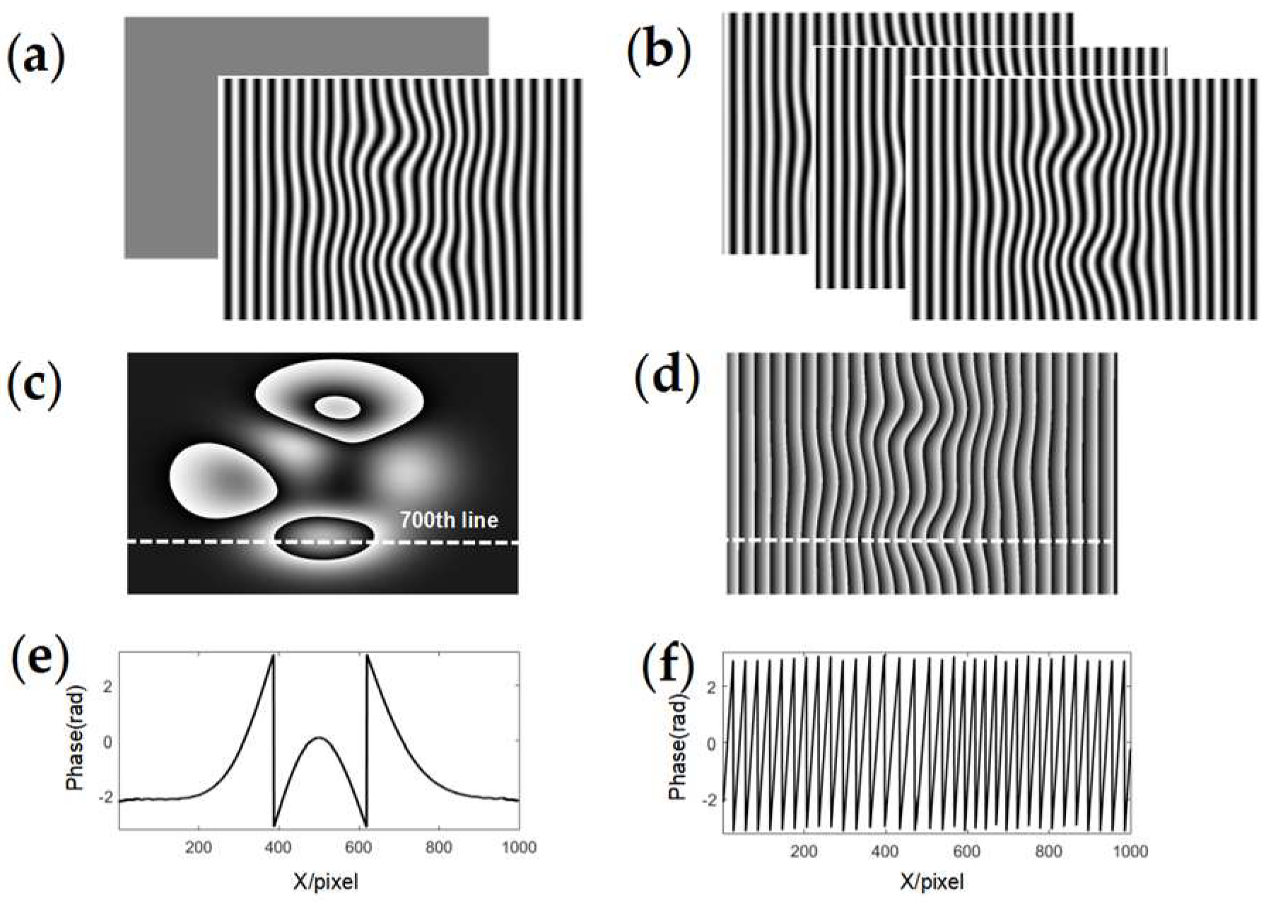
2.1. Principle of SCGMP

SCGMP involves two steps: preparation and measurement. In the preparation step, four-step phase-shifted fringes are used to collect the reference plane height, which can be expressed as:
I r e f n ( x , y ) = a r e f ( x , y ) + b r e f ( x , y ) cos [ 2 π f x + φ r e f ( x , y ) 2 π n / N ]
where a r e f ( x , y ) represents the background light intensity, b r e f ( x , y ) is the fringe modulation, f denotes the frequency, φ r e f ( x , y ) is the phase containing the height information of the reference plane, n = 0 ,   1 ,   2 ,   3 , and N = 4 . According to the complementarity between I r e f 0 ( x , y ) and I r e f 2 ( x , y ) , as well as I r e f 1 ( x , y ) and I r e f 3 ( x , y ) , two AC components with orthogonal phases can be obtained using the subtraction operation, as shown in Equation (2):
I r e f AC 0 ( x , y ) = 0.5 [ I r e f 0 ( x , y ) I r e f 2 ( x , y ) ] = b r e f ( x , y ) cos [ 2 π f x + φ r e f ( x , y ) ] I r e f AC 90 ( x , y ) = 0.5 [ I r e f 1 ( x , y ) I r e f 3 ( x , y ) ] = b r e f ( x , y ) sin [ 2 π f x + φ r e f ( x , y ) ]
Then, these two AC components are pre-stored in the computer as system parameters.
Next, in the measurement step, only two fringes with complementary phases are required to collect the surface information of the object, which can be expressed as:
I o b j 0 ( x , y ) = a o b j ( x , y ) + b o b j ( x , y ) cos [ 2 π f x + φ o b j ( x , y ) ] I o b j 1 ( x , y ) = a o b j ( x , y ) b o b j ( x , y ) cos [ 2 π f x + φ o b j ( x , y ) ]
where a o b j ( x , y ) and b o b j ( x , y ) represent the background light intensity and the modulation intensity, both of which are modulated by the object surface reflectivity. φ o b j ( x , y ) is the phase that contains the object height information. Then, the normalization operation, which is a necessary step, is performed on the two fringes to eliminate the effect of uneven reflectivity:
I o b j AC 0 ( x , y ) = I o b j 0 ( x , y ) I o b j 1 ( x , y ) I o b j 0 ( x , y ) + I o b j 1 ( x , y ) = b o b j ( x , y ) a o b j ( x , y ) cos [ 2 π f x + φ o b j ( x , y ) ]
Notably, in addition to addressing uneven reflectivity, the normalization also guarantees the feasibility of obtaining another phase-orthogonal normalized AC component through Hilbert transform, which is expressed in Equation (5):
I o b j AC 90 ( x , y ) = Hilbert [ I o b j AC 0 ( x , y ) ] = b o b j ( x , y ) a o b j ( x , y ) sin [ 2 π f x + φ o b j ( x , y ) ]
where Hilbert [·] denotes a π/2 phase-shifted operation. By multiplying the two orthogonal normalized AC components with two pre-stored AC components, respectively, two pairs of overlapping fringes are generated:
I o 1 ( x , y ) = I o b j AC 0 ( x , y ) I r e f AC 0 ( x , y ) = C { cos [ 4 π f x + φ o b j ( x , y ) + φ r e f ( x , y ) ] + cos [ φ o b j ( x , y ) φ r e f ( x , y ) ] } I o 2 ( x , y ) = I o b j AC 90 ( x , y ) I r e f AC 90 ( x , y ) = C { cos [ 4 π f x + φ o b j ( x , y ) + φ r e f ( x , y ) ] + cos [ φ o b j ( x , y ) φ r e f ( x , y ) ] }
I o 3 ( x , y ) = I o b j AC 0 ( x , y ) I r e f AC 0 ( x , y ) = C { sin [ 4 π f x + φ o b j ( x , y ) + φ r e f ( x , y ) ] + sin [ φ o b j ( x , y ) φ r e f ( x , y ) ] } I o 4 ( x , y ) = I o b j AC 90 ( x , y ) I r e f AC 90 ( x , y ) = C { sin [ 4 π f x + φ o b j ( x , y ) + φ r e f ( x , y ) ] sin [ φ o b j ( x , y ) φ r e f ( x , y ) ] }
where C = b r e f ( x , y ) b o b j ( x , y ) / a o b j ( x , y ) . In Equation (6), it can be observed that the two double-frequency components are opposites, while the DC components, also known as Moiré fringes, are the same. Similar relationships also exist in Equation (7). From this, the Moiré fringes can be extracted directly through spatial-domain calculations:
M 0 ( x , y ) = I o 1 ( x , y ) + I o 2 ( x , y ) = 2 C cos [ φ o b j ( x , y ) φ r e f ( x , y ) ]
M 90 ( x , y ) = I o 3 ( x , y ) I o 4 ( x , y ) = 2 C sin [ φ o b j ( x , y ) φ r e f ( x , y ) ]
Then, leveraging the phase-orthogonal characteristic of the two Moiré fringes, the wrapped phase can be obtained by applying the arctangent operation:
Δ φ ( x , y ) = φ o b j ( x , y ) φ r e f ( x , y ) = tan 1 [ M 90 ( x , y ) / M 0 ( x , y ) ]

2.2. Principle of the Proposed Method

2.2.1. Absolute Phase Retrieval

From the above illustration, it can be seen that SCGMP can extract the phase information just using spatial-domain calculations, which greatly ensures the integrity of the height information. Therefore, we further explore the merits of SCGMP and combine it with HDTPU to propose a novel dual-frequency method that can balance the measuring accuracy and speed well while addressing the restriction on high-fringe frequency selection in traditional HDTPU.
Based on SCGMP, our method also needs two steps. In the preparation step, four low-frequency fringes, expressed in Equation (11), are designed to collect the height of the reference plane:
I l _ r e f n ( x , y ) = a r e f ( x , y ) + b r e f ( x , y ) cos [ 2 π f l x + φ l _ r e f ( x , y ) 2 π n / N ]
where f l denotes the low frequency, and φ l _ r e f ( x , y ) is the phase containing the height of the reference plane. Next, due to complementarity relationships in I l _ r e f n ( x , y ) , two low-frequency AC components are obtained, as expressed in Equation (12):
I l _ r e f AC 0 ( x , y ) = 0.5 [ I l _ r e f 0 ( x , y ) I l _ r e f 2 ( x , y ) ] = b r e f ( x , y ) cos [ 2 π f l x + φ l _ r e f ( x , y ) ] I l _ r e f AC 90 ( x , y ) = 0.5 [ I l _ r e f 1 ( x , y ) I l _ r e f 3 ( x , y ) ] = b r e f ( x , y ) sin [ 2 π f l x + φ l _ r e f ( x , y ) ]
Using the same approach, we obtain two high-frequency AC components derived from four high-frequency fringes. Then, the resulting two pairs of AC components are pre-stored as the system parameters.
In the measurement step, the method requires only three patterns to collect the height information: a high-frequency fringe and a multi-period low-frequency fringe that share the same fringe parameters, except for the frequency, and a flat pattern that corresponds to the DC components of the two fringes. The expressions of the patterns can be calculated as:
I h _ o b j ( x , y ) = a o b j ( x , y ) + b o b j ( x , y ) cos [ 2 π f h x + φ h _ o b j ( x , y ) ]
I l _ o b j ( x , y ) = a o b j ( x , y ) + b o b j ( x , y ) cos [ 2 π f l x + φ l _ o b j ( x , y ) ]
I f l a t ( x , y ) = a o b j ( x , y )
where f h and f l denote the high and low frequencies. φ h _ o b j ( x , y ) is the phase carrying the height information of the measured object, and φ l _ o b j ( x , y ) is the phase providing the phase-unwrapping information.
According to SCGMP, the flat pattern in Equation (15) is multiplexed to simultaneously normalize the two fringes, thereby obtaining the two normalized AC components, which can be expressed as follows:
I h _ o b j AC 0 ( x , y ) = I h _ o b j ( x , y ) I f l a t ( x , y ) 1 = b o b j ( x , y ) a o b j ( x , y ) cos [ 2 π f h x + φ h _ o b j ( x , y ) ]
I l _ o b j AC 0 ( x , y ) = I l _ o b j ( x , y ) I f l a t ( x , y ) 1 = b o b j ( x , y ) a o b j ( x , y ) cos [ 2 π f l x + φ l _ o b j ( x , y ) ]
Next, the low-frequency normalized AC component I l _ o b j AC 0 ( x , y ) is first solved. Hilbert transform is performed on it to obtain another phase-orthogonal low-frequency normalized AC component, I l _ o b j AC 90 ( x , y ) :
I l _ o b j AC 90 ( x , y ) = Hilbert [ I l _ o b j AC 0 ( x , y ) ] = b o b j ( x , y ) a o b j ( x , y ) sin [ 2 π f l x + φ l _ o b j ( x , y ) ]
Then, I l _ o b j AC 0 ( x , y ) and I l _ o b j AC 90 ( x , y ) are overlapped with two pre-stored low-frequency AC components in Equation (12), respectively, through multiplication calculations:
I o 1 ( x , y ) = I l _ o b j AC 0 ( x , y ) I l _ r e f AC 0 ( x , y ) = C { cos [ 4 π f l x + φ l _ o b j ( x , y ) + φ l _ r e f ( x , y ) ] + cos [ φ l _ o b j ( x , y ) φ l _ r e f ( x , y ) ] } I o 2 ( x , y ) = I l _ o b j AC 90 ( x , y ) I l _ r e f AC 90 ( x , y ) = C { cos [ 4 π f l x + φ l _ o b j ( x , y ) + φ l _ r e f ( x , y ) ] + cos [ φ l _ o b j ( x , y ) φ l _ r e f ( x , y ) ] }
I o 3 ( x , y ) = I l _ o b j AC 0 ( x , y ) I l _ r e f AC 0 ( x , y ) = C { sin [ 4 π f l x + φ l _ o b j ( x , y ) + φ l _ r e f ( x , y ) ] + sin [ φ l _ o b j ( x , y ) φ l _ r e f ( x , y ) ] } I o 4 ( x , y ) = I l _ o b j AC 90 ( x , y ) I l _ r e f AC 90 ( x , y ) = C { sin [ 4 π f l x + φ l _ o b j ( x , y ) + φ l _ r e f ( x , y ) ] sin [ φ l _ o b j ( x , y ) φ l _ r e f ( x , y ) ] }
where C = b r e f ( x , y ) b o b j ( x , y ) / a o b j ( x , y ) . According to the simple mathematical relationships in Equations (19) and (20), two low-frequency Moiré fringes can be obtained just using spatial-domain calculations:
M 0 ( x , y ) = I o 1 ( x , y ) + I o 2 ( x , y ) = 2 C cos [ φ l _ o b j ( x , y ) φ l _ r e f ( x , y ) ]
M 90 ( x , y ) = I o 3 ( x , y ) I o 4 ( x , y ) = 2 C sin [ φ l _ o b j ( x , y ) φ l _ r e f ( x , y ) ]
Then, the low-frequency phase is extracted by applying the arctangent to the two Moiré fringes above:
Δ φ l ( x , y ) = φ l _ o b j ( x , y ) φ l _ r e f ( x , y ) = tan 1 [ M 90 ( x , y ) / M 0 ( x , y ) ]
It is worth noting that in traditional phase extraction methods, such as PMP, the phase derived from the multi-period low-frequency fringes typically suffers from 2π ambiguities. In contrast, the low-frequency phase in this paper is already continuous and requires no further unwrapping, as shown in Figure 1a; thus, it can be referred to as the basic phase and can be expressed as Δ Φ l ( x , y ) . As revealed in Ref. [1], the phase SNR is positively correlated with the fringe frequency. Based on this, compared to the basic phase derived from the single-period fringes in the traditional DHTPU, the proposed basic phase exhibits a higher accuracy and SNR.
For the high-frequency normalized AC component I h _ o b j AC 0 ( x , y ) , similar to the process used to obtain the low-frequency phase, by performing Equations (18)–(23), the high-frequency wrapped phase Δ φ h ( x , y ) , as shown in Figure 1b, can be extracted.
Under the robust guidance of the basic phase, the fringe order can be calculated by the hierarchical temporal phase-unwrapping algorithm [31]:
k ( x , y ) = r o u n d [ ( f h / f l ) Δ Φ l ( x , y ) Δ φ h ( x , y ) 2 π ]
Therefore, the 2π ambiguities of the wrapped phase can be eliminated to generate the final absolute phase Δ Φ h ( x , y ) :
Δ Φ h ( x , y ) = 2 π k ( x , y ) + Δ φ h ( x , y )

2.2.2. Analysis of Basic Phase Acquisition Conditions

Section 2.2.1 reveals that the basic phase can be directly extracted from the low-frequency fringe, which exhibits a higher SNR than the traditional one. However, to ensure the continuity of the basic phase, two necessary conditions should be met, which will be discussed in detail below.
For a traditional extracted phase represented as 2 π f x + φ , the frequency component 2 π f x is the main factor causing large phase ambiguities, which is a disadvantage for achieving the continuity of the basic phase. However, in SCGMP, this frequency component is precisely eliminated when generating Moiré fringes, as expressed in Equations (8) and (9), significantly alleviating the phase ambiguities. Therefore, SCGMP’s ability to eliminate the frequency component is the first necessary condition to ensure the continuity of the basic phase. Figure 2 presents two wrapped phases to better visualize the differences. Figure 2a shows the high-frequency fringe and the flat pattern used in our method. Figure 2b provides three equal-phase-shifted fringes that have the same frequency as the fringe in Figure 2a. By performing SCGMP and PMP, two wrapped phases, as displayed in Figure 2c,d, can be derived, respectively, and their cross-sections at the 700th line are displayed in Figure 2e,f. By comparison, it can be seen that the former wrapped phase exhibits milder phase ambiguities.
Secondly, after removing the interference of the frequency component, we only need to make sure the phase component φ , which is actually Δ Φ l in this paper, is continuous and distributed within the range of [−π, π]. Here, a commonly used phase-to-height mapping algorithm is expressed in Equation (26):
1 / H = c 1 + c 2 / Δ Φ l
where c 1 ,   c 2 are the calibrated coefficients. It can be seen that for a fixed measuring system, the amplitude of the basic phase is only affected by the height H and is positively correlated with it. Additionally, to ensure continuity, the basic phase must be distributed within the range of [−π, π]. Based on the above points, the measurable height range will be limited to a certain range. By substituting the phase extremums −π and π into Equation (26), the measurable height range can be obtained as:
π c 1 π c 2 H π c 1 π + c 2
Then, the maximum measurable height Δ H can be expressed as:
Δ H = π c 1 π + c 2 π c 1 π c 2 = 2 c 2 π c 2 2 c 1 2 π 2
Notably, the analysis approach of the basic phase acquisition condition is not limited to the simple phase-to-height algorithm in Equation (26) but is also valid for more complex calibration methods, as demonstrated in Refs. [48,49], because of the ever-present monotonic positive correlation between the basic phase amplitude and the height.
To clearly illustrate the maximum measurable height, the schematic diagram of the measuring system we built is shown in Figure 3. We employ the 10 periods/frame low-frequency grating to calibrate the system. A white, flat board, controlled by the stepper motor, is then moved forward in two increments: h1 = 15 mm and h2 = 32 mm, which serve as the given conditions for calibrating the coefficients c 1 and c 2 , so we can solve c 1 0.000954 and c 2 0.021 and substitute them into Equations (27) and (28). From this, the height constraint range can be obtained as ( 174.44 mm ,   130.83 mm ] , and the maximum measurable height Δ H is approximately 305.27 mm, which can nearly satisfy the measurement requirements for regular objects.

3. Experiments

The measuring system mainly comprised a camera and a projector. The camera was a Baumer HXC20 with 1028 × 2048 pixels, equipped with an 8 mm focal length lens. The projector was a Lightcrafter 4500 with 800 × 1280 pixels and the 120 fps maximum frame rate for 8-bit data. It synchronously triggered the camera to achieve real-time acquisition. The computer with an AMD Ryzen 7 5800H processor running at 3.2 GHz was utilized to process the captured images.

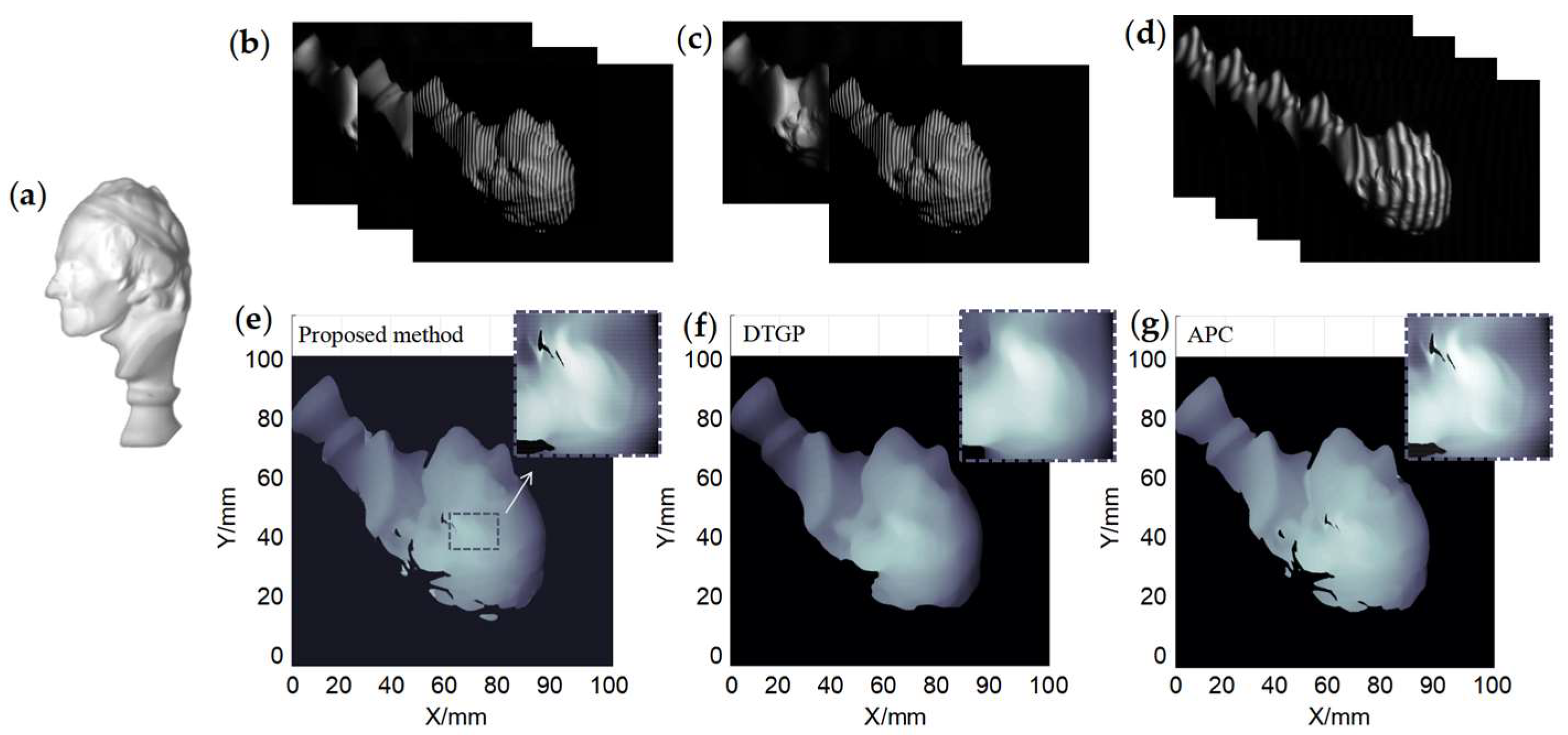
3.1. Accuracy Evaluation

To evaluate the performance of the proposed method, the dual-frequency three-step PMP (DFPMP) and multi-frequency three-step PMP (MFPMP) were selected for comparison. To ensure validity, all the methods employed the same 100 periods/frame high-frequency grating and completed the measurement under the same conditions. Differently, the proposed method utilized a 10 periods/frame low-frequency fringe to obtain the basic phase, while DFPMP and MFPMP employed the single-period fringes to achieve it.
Figure 4a shows the measured stair model. Figure 4b,c displays the captured high-frequency fringe and the low-frequency fringe, respectively, using the proposed method. Then, by performing SCGMP, Figure 4d,e shows the wrapped phase and the basic phase extracted from the above two fringes. To reflect the robustness of the basic phase, its cross-section (yellow curve) is shown together with that of MFPMP (blue curve) in Figure 4f. It can be seen that the yellow curve exhibited a smoother surface, while the blue curve had numerous burrs. This is attributed to the fact that the fringe with a higher frequency can better ensure the reliability and robustness of the extracted phase. Consequently, guided by the highly robust basic phase, Figure 4i displays the successfully reconstructed model using the proposed method, clearly displaying the smooth stair morphology and the sharp changes, verifying the feasibility of the proposed dual-frequency method. In contrast, guided by the noisy basic phase, the reconstructed result shown in Figure 4g failed to reflect the stair morphology, thereby indicating that the traditional dual-frequency method struggles to decode high-frequency fringe. Further, to exclude the effect of the over-large frequency ratio in DFPMP, the result using MFPMP, which had the same frequency ratio as the proposed method, is shown in Figure 4h. It can be seen that the result was notably better than that of DFPMP. However, since the basic phase was still obtained from the single-period fringes, the height jumps were still inevitable.
Additionally, the result of the multi-frequency eight-step PMP method was used as the quasi-truth value to validate the accuracy of the proposed method. Figure 4j shows the quasi-truth model. Figure 4k displays two cross-sections from the proposed method and the quasi-truth model. It can be seen that the two curves are tightly fit to each other, both in the global map and the enlarged local map.
For an intuitive comparison, we simulated a standard stair model to quantitatively evaluate the accuracy. The mean absolute error (MAE) and the root mean square error (RMSE) of Figure 4h–j are presented in Table 1. Additionally, we counted the number of error height jumps characterized by 2π integer multiples, also shown in Table 1.
The results indicated that the three-step MFPMP yielded relative larger errors, particularly in the number of jump errors. In comparison, the proposed method demonstrated a significantly higher accuracy and fewer error pixels, closely aligning with the quasi-truth values. This quantitative analysis further revealed the high robustness of the proposed basic phase and the high-accuracy performance of our method.
The above experiments revealed the limitation in conventional TPU and verified the superiority of our method. Next, we conducted comparisons with two state-of-the-art techniques: the two-shot dual-frequency temporal-geometric profilometry (DTGP) [36] and an advanced four-shot phase-coding method (APC) [37], the latter being a widely recognized TPU method. A head model with complex details, as shown in Figure 5a, was measured using all three methods. For both DTGP and our proposed method, we also employed the 100 periods/frame high-frequency fringe, while for APC, we set the frequency to 15 periods/frame because a larger frequency would cause the fringe orders to be difficult to distinguish. The captured fringes using the proposed method, DTGP, and APC are shown in Figure 5b–d, respectively. The reconstructed results are displayed in Figure 5e–g. Comparing Figure 5e with Figure 5f, especially in the enlarged views, the model using our method exhibited more clarity and provided more detailed information. It was precisely because DTGP used filters twice, which inevitably resulted in the loss of effective spectral components, leading to the loss of detailed height information. Thus, our method exhibited a better ability to preserve details. For Figure 5g, APC also reconstructed the detailed surfaces, showing a similar result to our method.
Since the results of our method and APC were hard to distinguish in the above experiment, we conducted a quantitative performance analysis using a cuboid that was 160 mm in length and width, with a height of 10 mm. Figure 6a–c displays three sets of captured fringes. Figure 6d–f provides the reconstructed surfaces and corresponding error distributions by comparing them with a simulated standard cuboid. The average height and RMSE of the three results are presented in the top left corner of Figure 6d–f. These metrics indicate that the accuracy of our method surpassed DTGP and slightly exceeded APC. In APC, fringe frequency was constrained by the need to distinguish the steps of the stair-like order. Thereby, this limitation, given the close relationship between fringe frequency and phase error, impacted the measuring accuracy to some degree. Although the accuracy of our method was only slightly higher than APC, it required one frame and fewer fringes, and the acquisition speed would be increased by 33% when considering dynamic measurement.

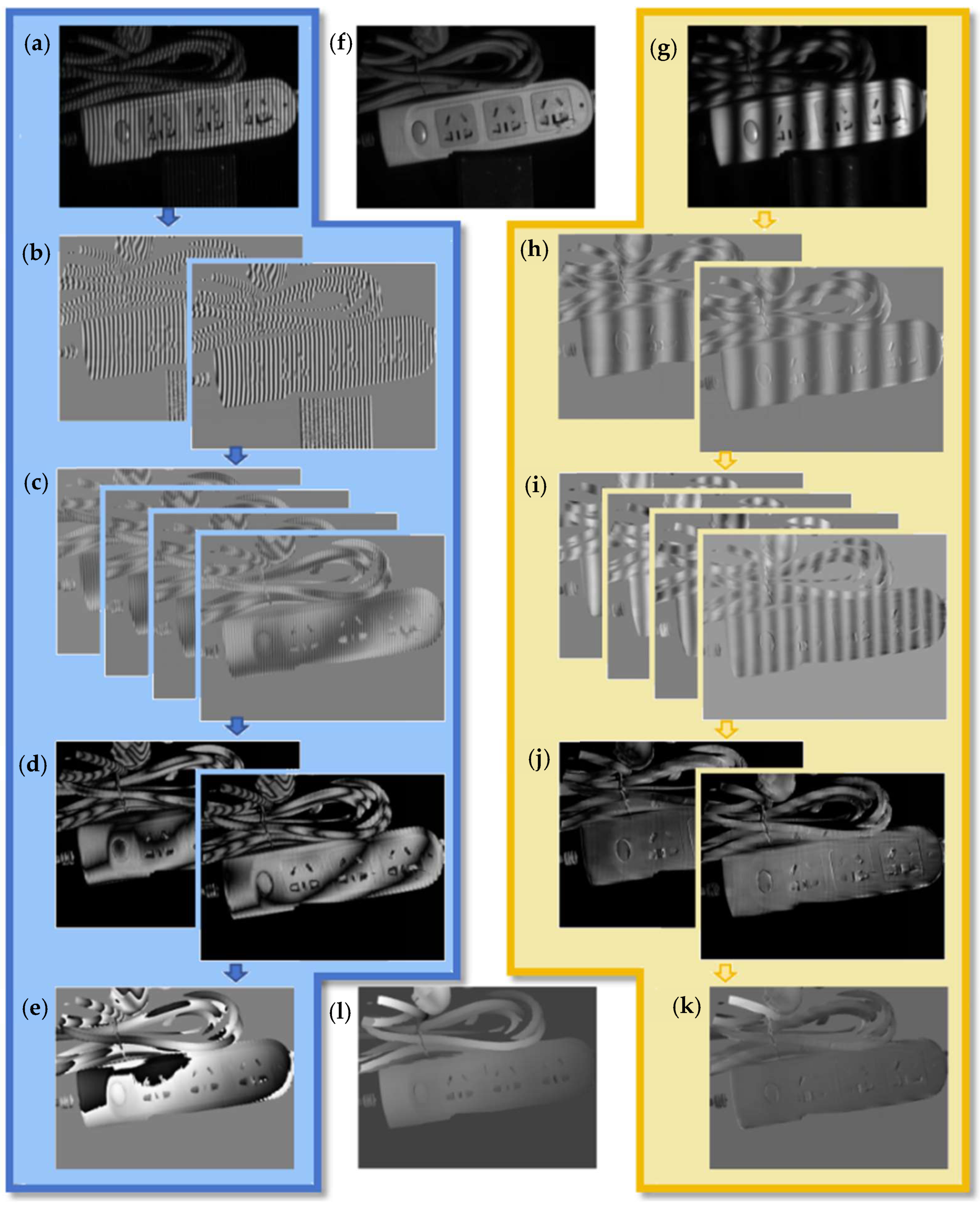
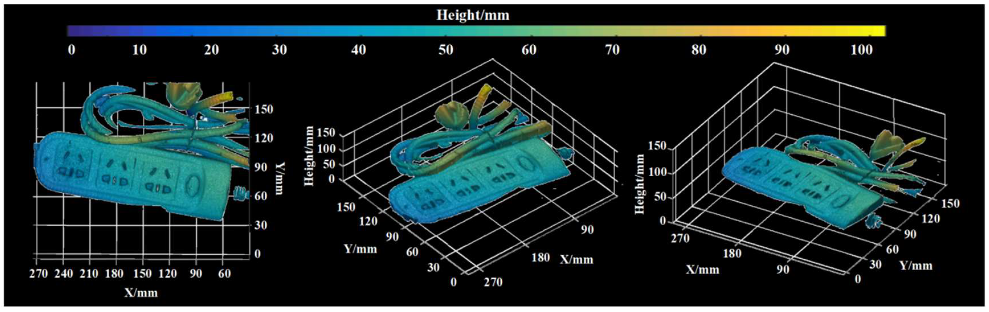
3.2. Robustness Verification

To verify the reconstruction ability for complex objects, a power strip with twisting electric wires was measured. Figure 7a shows the captured high-frequency fringe. Figure 7b shows the two orthogonal normalized AC components, which were extracted from Figure 7a through normalization and Hilbert transformation. By multiplying them with the pre-restored AC components of the reference plane, four overlapping fringes, as shown in Figure 7c, were generated. Leveraging the algebraic relationships between the overlapped fringes, two Moiré fringes standing for the sine and cosine of the phase, as shown in Figure 7d, was purified entirely in the spatial domain. From this, the final wrapped phase was obtained using the arctangent operation and is shown in Figure 7e. It can be seen from Figure 7e that the 2π-phase ambiguities were significantly reduced because the frequency component was eliminated when extracting the Moiré fringes. Then, with the same algorithms, the low-frequency fringe in Figure 7g was decoded step-by-step, as shown in Figure 7h–j, until the basic phase in Figure 7k was extracted. Guided by this highly robust basic phase, the phase ambiguities of the wrapped phase were effectively eliminated. From this, the obtained absolute phase is shown in Figure 7l. To present the reconstructed model comprehensively, Figure 8 displays it from different viewing angles, which strongly proves the robustness of the proposed method in reconstructing complex objects.
To verify the ability of uneven reflectivity resistance, we measured a smooth mask painted in various colors. Figure 9a shows the captured high-frequency fringe, and Figure 9b shows the reconstructed model using the proposed method. For comparison, Figure 9c shows a model obtained by the same method, except the AC component was derived by directly subtracting the flat pattern from the captured fringes instead of through normalization. Additionally, we selected the result shown in Figure 9d using the 8-step PMP as the quasi-truth value, due to its excellent resistance to uneven reflectivity and high precision. It was observed that the model in Figure 9b effectively reconstructed the smooth surface, closely matching the quasi-truth value and demonstrating a strong performance against uneven reflectivity. In contrast, Figure 9c reveals the obvious error ripples because the reflectivity coefficient cannot be eliminated solely through subtraction. Therefore, the normalization operation in our method was essential for accurately measuring color objects, and the comparative results indicated that this method was capable of effectively measuring color objects.
Since the proposed method employed only three shots, it had a great potential for high-speed reconstruction of the dynamic scene. To verify this, a hand model placed on a rotating disc was measured in real-time. The camera captured the moving model at 144 frames per second (fps), and correspondingly, the proposed method achieved real-time reconstruction at 38 fps. Figure 10a shows the five high-frequency fringes captured at different times. Figure 10b shows the successful reconstructed models at corresponding times, which can reflect the hand models from different angles.

3.3. Discussion

In this section, we present an overall discussion of the experimental results. In the initial stair experiment, the limitation of traditional HTPU was revealed using dual-frequency and multi-frequency PMPs, which extracted the low-SNR basic phase from fringes with a frequency of only 1 period/frame. The limitation restricted the selection of high-frequency fringes and potentially led to error jumps in the reconstructed surface. In contrast, our proposed method overcame the limitation and employed low-frequency fringes with a frequency of up to 10 periods/frame. This innovation significantly improved the SNR of the basic phase, eliminating the restriction on high frequency and ensuring the high accuracy of the reconstructed surfaces as well. Furthermore, we compared it with advanced techniques, including dual-frequency temporal-geometric profilometry and the improved phase-coding method. As demonstrated by the experimental results, our method had a better accuracy than DTGP because of total spatial-domain calculations, and it increased about 33% for measuring speed, compared with APC, while maintaining a similar accuracy, revealing the ability to effectively balance measurement accuracy and speed simultaneously. The high adaptability of our method was subsequently confirmed through successful reconstructions of complex and colored objects. Finally, we extended the application of our method to a high-speed scenario by measuring a rotating hand model.

4. Conclusions

A novel dual-frequency method based on spatial computer-generated Moiré profilometry is proposed in this paper. The method effectively solves two main problems in traditional DHTPU: the challenge of balancing measurement accuracy and speed and the limitation on high-frequency selection. By leveraging the full spatial-domain calculations of SCGMP, the integrity and accuracy of the extracted phase information are ensured. By cleverly multiplexing the flat pattern, the required number of fringes is reduced to three, making this method well-suited for high-speed measurement. Additionally, we developed SCGMP’s ability to alleviate phase ambiguities and also provided the algorithm for determining the maximum measurable height range for the fixed system. These two aspects enable the basic phase derived from the multi-period low-frequency fringe to exhibit a higher SNR than that obtained by traditional DHTPU methods, effectively releasing the limitation on the high-frequency selection. Experimental results demonstrate that this method achieves high accuracy measurement by utilizing a 100 periods/frame high-frequency fringe and performs with high robustness in complex object reconstruction and high-speed dynamic scene measurement.

Supplementary Materials

The following supporting information can be downloaded at: https://www.mdpi.com/article/10.3390/photonics11080758/s1.

Author Contributions

H.Z.: conceptualization, methodology, software, data curation, and writing—original draft preparation. J.Z. and D.J.: methodology, investigation, data curation, and supervision. J.H.: investigation and formal analysis. J.Y.: validation and visualization. All authors have read and agreed to the published version of the manuscript.

Funding

This research received no external funding.

Institutional Review Board Statement

Not applicable.

Informed Consent Statement

Not applicable.

Data Availability Statement

Data will be made available upon request.

Conflicts of Interest

The authors declare that they have no known competing financial interests or personal relationships that could have appeared to influence the work reported in this paper.

References

  1. Zuo, C.; Feng, S.J.; Huang, L.; Tao, T.Y.; Yin, W.; Chen, Q. Phase shifting algorithms for fringe projection profilometry: A review. Opt. Laser Eng. 2018, 109, 23–59. [Google Scholar] [CrossRef]
  2. Tan, J.; Su, W.; He, Z.; Bai, Y.; Dong, B.; Xie, S. Generic saturation-induced phase error correction for structured light 3D shape measurement. Opt. Lett. 2022, 47, 3387–3390. [Google Scholar] [CrossRef] [PubMed]
  3. Wang, B.Y.; Yu, X.Y.; Wu, H.B.; Zhang, J.X.; Meng, X.L. Phase-unwrapping approach based on dual-frequency analog structured light. Opt. Commun. 2017, 382, 272–280. [Google Scholar] [CrossRef]
  4. Wu, Z.J.; Guo, W.B.; Zhang, Q.C. High-speed three-dimensional shape measurement based on shifting Gray-code light. Opt. Exp. 2019, 27, 22631–22644. [Google Scholar] [CrossRef]
  5. Zheng, Z.J.; Gao, J.; Mo, J.H.; Zhang, L.Y.; Zhang, Q.F. A fast self-correction method for nonlinear sinusoidal fringe images in 3-D measurement. IEEE Trans. Instrum. Meas. 2021, 70, 1–9. [Google Scholar] [CrossRef]
  6. Tan, J.; Liu, J.; Wang, X.; He, Z.; Su, W.; Huang, T.; Xie, S. Large depth range binary-focusing projection 3D shape reconstruction via unpaired data learning. Opt. Laser Eng. 2024, 181, 108442. [Google Scholar] [CrossRef]
  7. Takeda, M.; Mutoh, K. Fourier transform profilometry for the automatic measurement 3D object shapes. Appl. Opt. 1983, 22, 3977–3982. [Google Scholar] [CrossRef] [PubMed]
  8. Liu, H.Q.; Chen, W.J.; Su, X.Y.; Chen, F. Fast Fourier transform profilometry based on two-frequency grating projection. Opto-Electron. Eng. 2004, 31, 39. [Google Scholar]
  9. Li, J.; Su, X.Y.; Guo, L.R. Improved fourier transform profilometry for the automatic measurement of 3-dimensional object shapes. Opt. Eng. 1990, 29, 1439–1444. [Google Scholar]
  10. Zuo, C.; Tao, T.Y.; Feng, S.J.; Huang, L.; Asundi, A.; Chen, Q. Micro fourier transform profilometry (μftp): 3D shape measurement at 10,000 frames per second. Opt. Laser Eng. 2018, 102, 70–91. [Google Scholar] [CrossRef]
  11. Hong, G.; Huang, P.S. 3-D shape measurement by use of a modified Fourier transform method. Proc. SPIE 2008, 7066, 104–111. [Google Scholar]
  12. Dai, M.Y.; Peng, K.; Zhao, J.; Wan, M.L.; Wang, W.F.; Cao, Y.P. Fast 3D measurement based on improved optical flow for dynamic objects. Opt. Exp. 2020, 28, 18969–18985. [Google Scholar] [CrossRef] [PubMed]
  13. Kuang, P.; Cao, Y.P.; Li, K. A new pixel matching method using the entire modulation of the measured object in online PMP. Optik 2014, 125, 137–140. [Google Scholar]
  14. Zheng, D.L.; Da, F.P.; Qian, K.M.; Seah, H.S. Phase-shifting profilometry combined with Gray-coded patterns projections: Unwrapping error removal by an adaptive median filter. Opt. Exp. 2017, 25, 4700–4713. [Google Scholar] [CrossRef] [PubMed]
  15. Takasaki, H. Moiré topography from its birth to practical application. Opt. Laser Eng. 1982, 3, 3–14. [Google Scholar] [CrossRef]
  16. Takasaki, H. Moiré topography. Appl. Opt. 1970, 9, 1467–1472. [Google Scholar] [CrossRef] [PubMed]
  17. Yoshizawa, T.; Tomisawa, T. Shadow moiré topography by means of the phase-shifted method. Opt. Eng. 1993, 32, 1668–1674. [Google Scholar] [CrossRef]
  18. Halioua, M.; Krishnamurthy, R.; Liu, H.; Chang, F. Projection moiré with moving gratings for automated 3-D topography. Appl. Opt. 1983, 22, 850. [Google Scholar] [CrossRef] [PubMed]
  19. Mohammadi, F.; Kofman, J. Single-frame digital phase-shifting 3D shape measurement using pixel-wise moiré-wavelength refinement. Opt. Laser Eng. 2016, 78, 196–204. [Google Scholar] [CrossRef]
  20. Mohammadi, F.; Kofman, J. Improved grid-noise removal in single frame digital moiré 3D shape measurement. Opt. Laser Eng. 2016, 86, 143–155. [Google Scholar] [CrossRef]
  21. Li, C.M.; Cao, Y.P.; Chen, C.; Wan, Y.Y.; Fu, G.K.; Wang, Y.P. Computer-generated Moiré profilometry. Opt. Exp. 2017, 25, 26815–26824. [Google Scholar] [CrossRef] [PubMed]
  22. Li, C.M.; Cao, Y.P.; Wang, L.; Wan, Y.Y.; Fu, G.K.; Wang, Y.P.; Chen, C. High precision computer-generated moiré profilometry. Sci. Rep. 2019, 9, 7804. [Google Scholar] [CrossRef] [PubMed]
  23. Li, C.M.; Cao, Y.P.; Wan, Y.Y.; Li, H.M.; Xu, C.; Zhang, H.C. Computer-generated frequency-carrier moiré profilometry. Opt. Commun. 2021, 501, 127381. [Google Scholar] [CrossRef]
  24. Li, H.; Cao, Y.; Wan, Y.; Li, C.; Xu, C.; Zhang, H.; An, H. A super-grayscale and real-time computer-generated Moiré profilometry using video grating projection. Sci. Rep. 2021, 11, 19882. [Google Scholar] [CrossRef]
  25. Zhang, H.C.; Cao, Y.P.; Li, C.M.; Wang, L.; Li, H.M.; Xu, C.; Wan, Y.Y. Color-encoded computer-generated Moiré profilometry with real-time 3D measurement and synchronous monitoring video collection. Opt. Eng. 2021, 60, 034109. [Google Scholar] [CrossRef]
  26. Zhang, H.C.; Cao, Y.P.; Li, C.M.; Wang, L.; Li, H.M.; Xu, C.; Wan, Y.Y. Color-encoded single-shot computer-generated Moiré profilometry. Sci. Rep. 2021, 1, 11020. [Google Scholar] [CrossRef]
  27. Zhang, H.C.; Cao, Y.P.; Li, H.M.; An, H.H.; Wu, H.T. Spatial computer-generated Moire profilometry. Sens. Actuators A Phys. 2024, 367, 115054. [Google Scholar] [CrossRef]
  28. Chen, K.; Xi, J.T.; Yu, Y.G. Quality-guided spatial phase unwrapping algorithm for fast three-dimensional measurement. Opt. Commun. 2013, 294, 139–147. [Google Scholar] [CrossRef]
  29. Liu, X.R.; Kofman, J. High-frequency background modulation fringe patterns based on a fringe-wavelength geometry-constraint model for 3D surface-shape measurement. Opt. Exp. 2017, 25, 16618–16628. [Google Scholar] [CrossRef]
  30. Cheng, T.; Du, Q.; Jiang, Y. Color fringe projection profilometry using geometric constraints. Opt. Commun. 2017, 398, 39–43. [Google Scholar] [CrossRef]
  31. Zuo, C.; Huang, L.; Zhang, M.L.; Chen, Q.; Asundi, A. Temporal phase unwrapping algorithms for fringe projection profilometry: A comparative review. Opt. Laser Eng. 2016, 85, 84–103. [Google Scholar] [CrossRef]
  32. Su, X.Y.; Chen, W.J. Reliability-guided phase unwrapping algorithm: A review. Opt. Lasers Eng. 2004, 42, 245–261. [Google Scholar] [CrossRef]
  33. Wang, J.; Yang, Y. Branch-cut algorithm with fast search ability for the shortest branch-cuts based on modified GA. J. Mod. Opt. 2019, 66, 473–485. [Google Scholar] [CrossRef]
  34. Arevalillo-Herraez, M.; Villatoro, F.R.; Gdeisat, M.A. A robust and simple measure for quality-guided 2D phase unwrapping algorithms. IEEE Trans. Image Process. 2016, 25, 2601–2609. [Google Scholar] [CrossRef] [PubMed]
  35. Wu, Z.J.; Guo, W.B.; Li, Y.Y.; Liu, Y.H.; Zhaang, Q.C. High-speed and high-efficiency three-dimensional shape measurement based on gray coded light. Photonics Res. 2020, 8, 819–829. [Google Scholar] [CrossRef]
  36. Zheng, D.L.; Kemao, Q.; Da, F.P.; Seah, H.S. Ternary gray code based phase unwrapping for 3D measurement using binary patterns with projector defocusing. Appl. Opt. 2017, 56, 3660–3665. [Google Scholar] [CrossRef]
  37. Wang, Y.J.; Zhang, S. Novel phase-coding method for absolute phase retrieval. Opt. Lett. 2012, 37, 2067–2069. [Google Scholar] [CrossRef] [PubMed]
  38. An, H.H.; Cao, Y.P.; Li, H.M.; Zhang, H.C. Temporal Phase Unwrapping Based on Unequal Phase-Shifting Code. IEEE Trans. Image Process. 2023, 32, 1432–1441. [Google Scholar] [CrossRef] [PubMed]
  39. Wang, J.H.; Yang, Y.X. Phase extraction accuracy comparison based on multi-frequency phase-shifting method in fringe projection profilometry. Measurement 2022, 199, 111525. [Google Scholar] [CrossRef]
  40. Li, L.; Zheng, Y.; Yang, K.; Su, X.; Wang, Y.W.; Chen, X.C.; Wang, Y.J.; Li, B.W. Modified three-wavelength phase unwrapping algorithm for dynamic three-dimensional shape measurement. Opt. Commun. 2021, 480, 126409. [Google Scholar] [CrossRef]
  41. Wu, Z.J.; Guo, W.B.; Zhang, Q.C. Two-frequency phase-shifting method vs. Gray-coded-based method in dynamic fringe projection profilometry: A comparative review. Opt. Laser Eng. 2022, 153, 106995. [Google Scholar] [CrossRef]
  42. Li, J.L.; Su, H.J.; Su, X.Y. Two-frequency grating used in phase-measuring profilometry. Appl. Opt. 1997, 36, 277–280. [Google Scholar] [CrossRef] [PubMed]
  43. Guo, W.B.; Wu, Z.J.; Xu, R.C.; Zhang, Q.C.; Fujigaki, M. A fast reconstruction method for three-dimensional shape measurement using dual-frequency grating projection and phase-to-height lookup table. Opt. Laser Technol. 2019, 112, 269–277. [Google Scholar] [CrossRef]
  44. Liu, K.; Wang, Y.C.; Lau, D.; Hao, Q.; Hassebrook, L.G. Dual-frequency pattern scheme for high-speed 3-D shape measurement. Opt. Exp. 2010, 18, 5229–5244. [Google Scholar] [CrossRef] [PubMed]
  45. Dai, M.L.; Yang, F.J.; Liu, C.; He, X.Y. A dual-frequency fringe projection three-dimensional shape measurement system using a DLP 3D projector. Opt. Commun. 2017, 382, 294–301. [Google Scholar] [CrossRef]
  46. Qiao, N.; Quan, C. Dual-frequency fringe projection for 3D shape measurement based on correction of gamma nonliearity. Opt. Laser Technol. 2018, 106, 378–384. [Google Scholar] [CrossRef]
  47. Li, H.M.; Cao, Y.P.; Wu, H.T.; Xu, C.; Zhang, H.C.; An, H.H. A dual-frequency temporal-geometric phase unwrapping based on computer-generated frequency-carrier Moiré profilometry. Measurement 2022, 200, 111606. [Google Scholar] [CrossRef]
  48. Li, W.; Su, X.; Liu, Z. Large-scale three-dimensional object measurement: A practical coordinate mapping and image data-patching method. Appl. Opt. 2001, 40, 3326–3333. [Google Scholar] [CrossRef]
  49. Ma, Q.N.; Cao, Y.P.; Chen, C.; Wan, Y.Y.; Fu, G.K.; Wang, Y.P. Intrinsic feature revelation of phase-to-height mapping in phase measuring profilometry. Opt. Laser Technol. 2018, 108, 46–52. [Google Scholar] [CrossRef]
Figure 1. Phase diagram. (a) The continuous low-frequency phase and (b) high-frequency wrapped phase.
Photonics 11 00758 g001
Figure 2. Phase comparison. (a) The flat pattern and high-frequency fringe, (b) three high-frequency fringes with equal phase shifts, (c) phase using the proposed method, and (d) phase using PMP; (e,f) cross-sections of (c,d).
Photonics 11 00758 g002
Figure 3. The schematic diagram of the measuring system.
Photonics 11 00758 g003
Figure 4. Reconstructed results of the stair model. (a) Stair (b) high-frequency pattern; (c) low-frequency pattern; (d) wrapped phase; (e) basic phase; and (f) basic phase comparison. (gj) Reconstructed models by DFPMP, MFPMP, the proposed method, and the 8-step PMP. (k) Cross-section comparison of (i,j).
Photonics 11 00758 g004
Figure 5. Comparison experiments. (a) Measured model, (bd) three sets of captured fringes, and (eg) three reconstructed models.
Photonics 11 00758 g005
Figure 6. Quantitative comparison. (ac) Captured fringes by the proposed method, DTGP, and APC; (df) reconstructed models and error distributions of the three methods.
Photonics 11 00758 g006
Figure 7. Reconstructed power strip. (a) High-frequency fringe, (b) two normalized AC components, (c) four superposed fringes, (d) two Moiré fringes, (e) wrapped phase, (f) average intensity, (g) low-frequency fringe, (h) two normalized AC components, (i) four superposed fringes, (j) two Moiré fringes, (k) basic phase, and (l) absolute phase.
Photonics 11 00758 g007
Figure 8. The reconstructed model at different statuses.
Photonics 11 00758 g008
Figure 9. Color object measurement. (a) The high-frequency fringe, (b) model using 8-step PMP, (c) model using the proposed method, and (d) the proposed method without normalization.
Photonics 11 00758 g009
Figure 10. Measurement results of the dynamic scene. (a) Five high-frequency fringes at different times and (b) five reconstructed models at the corresponding times (The reconstructed video can be seen in Supplementary Materials).
Photonics 11 00758 g010
Table 1. Accuracy verification of the three methods.
Three-Step MFPMPProposed MethodEight-Step MFPMP
MAE (mm)0.0270.0150.012
RMSE (mm)0.0640.0270.023
Error pixel53711060949
Disclaimer/Publisher’s Note: The statements, opinions and data contained in all publications are solely those of the individual author(s) and contributor(s) and not of MDPI and/or the editor(s). MDPI and/or the editor(s) disclaim responsibility for any injury to people or property resulting from any ideas, methods, instructions or products referred to in the content.

