Communication

Research on High-Frequency PGC-EKF Demodulation Technology Based on EOM for Nonlinear Distortion Suppression

1
Electric Power Research Institute, State Grid Jiangsu Electric Power Co., Ltd., Nanjing 211103, China
2
Key Laboratory of Specialty Fiber Optics and Optical Access Networks, Joint International Research Laboratory of Specialty Fiber Optics and Advanced Communication, Shanghai Institute for Advanced Communication and Data Science, Shanghai University, Shanghai 200444, China
*
Author to whom correspondence should be addressed.
Photonics 2024, 11(9), 801; https://doi.org/10.3390/photonics11090801
Submission received: 27 June 2024 / Revised: 8 August 2024 / Accepted: 21 August 2024 / Published: 27 August 2024
(This article belongs to the Special Issue Advanced Optical Fiber Sensors for Harsh Environment Applications)

Abstract

:
In this study, a phase-generated carrier (PGC) demodulation algorithm combined with the extended Kalman filter (EKF) algorithm based on an electro-optic modulator (EOM) is proposed, which can achieve nonlinear distortion (such as modulation depth drift and carrier phase delay) suppression for high-frequency phase carrier modulation. The improved algorithm is implemented on a field-programmable gate array (FPGA) hardware platform. The experimental results by the PGC-EKF method show that total harmonic distortion (THD) decreases from −32.61 to −54.51 dB, and SINAD increases from 32.59 to 47.86 dB, compared to the traditional PGC-Arctan method. This indicates that the PGC-EKF demodulation algorithm proposed in this paper can be widely used in many important fields such as hydrophone, transformer, and ultrasound signal detection.

1. Introduction

The phase-generated carrier (PGC) demodulation algorithm has the advantages of a high resolution, large dynamic range, strong real-time demodulation ability, and good linearity [1,2]. The algorithm has widely been used in the signal processing of interferometric sensors such as Michelson, Mach Zehnder, and Fabry–Pérot. In recent years, high-precision detection in partial discharge detection [3,4], underwater targets [5,6], ultrasonic signals [7,8], and other military and civilian fields have gradually become research hotspots.
With the development of optical devices, electro-optic modulators (EOMs) with a high modulation frequency and high inherent modulation bandwidth have received widespread attention, which achieves PGC external modulation [9,10]. A high-frequency carrier wave means an increase in the frequency range and dynamic range of the demodulated signal. However, the external modulation method based on EOM is not conducive to achieving the full optical fiber of the system and forming large-scale sensor arrays [11].
The traditional PGC demodulation methods mainly include differential-cross-multiplication (DCM) and arctangent (Arctan) algorithms. The two schemes require a specific phase modulation depth C value (DCM is 2.37 rad, and Arctan is 2.63 rad) [12,13], and it works properly when a phase delay θ is 0. However, in practical applications, the long-distance transmission of signals, the conversion delay of optical devices, and the unstable power of modulators, as well as fluctuations in the external environment, may cause the fluctuation of the phase modulation depth C value. These will all result in nonlinear distortion to the demodulated signal [14,15]. In recent years, many improved algorithms such as the known PGC-DSM-Atan [16], PGC-RCM [17], PGC-Elim-B [18], PGC-Elim-BC [19], and PGC-SDD [20] have been proposed, which were used to eliminate the influence of modulation depth changes. Moreover, A.V. Volkov et al. proposed a correction scheme for C value evaluation [21]. These methods are not sensitive to changes in modulation depth. But if there is a carrier phase delay in the system, the demodulation of the signal still exhibits nonlinear distortion [22]. The ellipse fitting algorithm (EFA) based on least squares can suppress nonlinear distortion caused by the phase delay and C value changes [23,24], and improved ellipse fitting algorithms have also been proposed [25,26]. However, overly complex models can increase computation time and hardware resource consumption [27]. As the extended form of the Kalman filter (KF), the extended Kalman filter (EKF) is used for the state estimation of nonlinear systems. By using a Taylor series expansion, the nonlinear system is linearized, thus transforming the nonlinear problem into a linear one. EKF has been widely used in the state-of-charge (SOC) estimation of battery management systems (BMSs) [28], abnormal data inspection of photovoltaic power generation [29], and real-time orbit determination of satellite navigation systems [30].
In this paper, a more universal nonlinear distortion model that is used to estimate parameters by the EKF algorithm is proposed. It has universality and effectiveness without increasing the algorithm complexity. A high-frequency PGC demodulation system based on EOM is built. High-frequency phase modulation can be achieved by utilizing EOM, which is beneficial for the multiplexing system. Finally, the effectiveness of the proposed scheme is verified through experiments.

2. Principle of Demodulation Algorithm of PGC

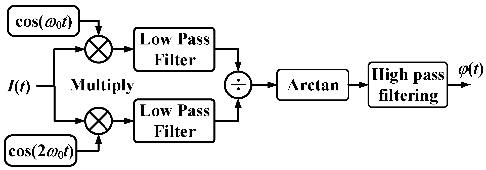
2.1. Principle of PGC-Arctan

The interference light signal is received by a photodetector (PD) and then converted into an electrical signal. The analog-to-digital converter (ADC) quantizes the electrical signal into a digital signal for subsequent signal demodulation. The principle of the traditional PGC-Arctan demodulation algorithm is shown in Figure 1.
The digitized interference signal I(t) can be expressed as:
I t = A + B cos C cos ω 0 t + θ + φ t
where A is the DC component, B is the AC component, cos(ω0t) is the carrier modulation signal, C is the phase modulation depth, ω0 is the carrier frequency, θ is the carrier phase delay, and φ(t) is the phase signal to be measured that contains the AC and DC components’ information.
Two signals can be obtained by multiplying the interference signal with the fundamental frequency signal and the second harmonic signal of the carrier wave, respectively. The high-frequency carrier term of the two signals is filtered out through low-pass filters, which can be expressed as:
I x t = L P F I t cos w 0 t = B J 1 C cos θ sin φ t
I y t = L P F I t cos 2 w 0 t = B J 2 C cos 2 θ cos φ t
where LPF[] represents a low-pass filter, and J1(C) and J2(C) are the first-order and second-order Bessel functions of modulation depth C, respectively.
After dividing Equations (3) and (4), the divided signal can be obtained by using the arctangent operation and a high-pass filter:
Φ t = arctan cos θ cos 2 θ J 1 C J 2 C tan φ t
When J1(C) = J2(C) and θ = 0, the test signal can be accurately demodulated by the PGC-Arctan algorithm.
In practical engineering applications, due to changes in the external environmental temperature, there is the circuit drift question, and the half-wave voltage of the phase modulator may also be unstable, leading to the dynamic change of C. Moreover, because of the long-distance transmission of signals and the conversion delay of optical devices, there will be a phase delay θ between the carrier term of the interference signal and the reference carrier of the mixing. Generally, some nonlinear distortion also influence the demodulated signal, which exhibits severe nonlinear distortion.
Therefore, Equations (2) and (3) will be rewritten as follows:
P t = h + a sin φ t
Q t = k + b cos φ t δ
where h and k are the DC offsets of the two signals, a and b are the AC amplitudes of the two signals, respectively, and δ is the phase difference between P(t) and Q(t).
Since h, k, a, b, and δ are all unknown quantities, the phase signal φ(t) is not directly separated from P(t) and Q(t). Therefore, the EKF algorithm is employed to estimate these five parameters in real time.

2.2. Principle of PGC-EKF

EKF is an extended form of the standard Kalman filter in nonlinear situations, the basic idea of which is to linearize the nonlinear system using Taylor series expansion. Then, filter the signal through the Kalman filter framework, and, finally, optimize some quantities that cannot be directly measured but can be indirectly measured. Therefore, it can also be called the optimization estimation algorithm [31].
The principle of the PGC demodulation algorithm based on EKF is shown in Figure 2. The two output signals by low-pass filtering are converted into two forms, which can be expressed as:
sin φ t = P t h / a
cos φ t = Q t k b cos δ sin φ t sin δ cos δ
Equations (7) and (8) satisfy the general ellipse equation:
x 2 + E x y + F y 2 + G x + H y + M = 0
where the elliptical parameters E, F, G, H, and M can be expressed as:
E = 2 a sin δ / b F = a 2 / b 2 G = 2 a k sin δ / b 2 h H = 2 a h sin δ / b 2 a 2 k / b 2 M = h 2 + a 2 b 2 k 2 2 a h k sin δ / b a 2 cos 2 δ
The elliptical parameters form a five-dimension vector Xk, which is the state vector of EKF for estimation and prediction. Therefore, a system model of Kalman filtering consisting of input signals P(t) and Q(t), and state vector Xk can be established. The state equation and observation equation of EKF are written as:
X k = X k 1
Z k = N k X k 1 + v
where Xk (=[E, F, G, H, M]T) is the observation matrix, Zk is the system observation vector, Xk = [E, F, G, H, M]T, and ν is observation noise, the mean value of which is zero. The covariance matrix is the additive Gaussian white noise of Qn.
Figure 2. Schematic diagram of PGC-EKF demodulation.
Photonics 11 00801 g002
The detailed implementation process of EKF is shown in Figure 3, where Xk+ and Pk+ are the state vector and the covariance matrix at time k, respectively. The symbols − and + represent the values before and after the EKF measurement update. During the update period, when the change of two adjacent estimation results is less than the given error of 10−6, EKF converges, or it continuously updates. When EKF converges, a set of parameters E, F, G, H, and M can be obtained. According to Equation (10), h, k, a, b, and δ can be derived, which are expressed as:
h = 2 F G E H / E 2 4 F k = 2 H E G / E 2 4 F a = s q r t h 2 + k 2 F + h k E M / 1 E 2 / 4 F b = s q r t a 2 / F δ = sin 1 E / 2 F
Considering the high computational complexity of the EKF algorithm, the calculation of parameters h, k, a, b, and δ will not continue with the Kalman filtering process. It will only be executed after the convergence of EKF. Then, the values of parameters h, k, a, b, and δ will be updated after execution.
By substituting the obtained parameters h, k, a, b, and δ into Equations (7) and (8), two orthogonal signals can be obtained:
P t = sin φ t = P x t h / a
Q t = cos φ t = Q y t k b cos δ sin φ t sin δ cos δ
The phase signal can be obtained when dividing Equations (14) and (15), and then performing the arctangent operation.
In the field-programmable gate array (FPGA), the coordinate rotation digital computer (CORDIC) is used to replace the division and arctangent operations. This algorithm can recursively calculate the function values such as Sin, Cos, Sinh, Cosh, Arctan, etc., by the shift and addition and subtraction operations. It should be noted that the signal range is resolved by the CORDIC algorithm is [−π, +π], which differs by 2nπ from the actual signal. Thus, it is necessary to expand the range of the demodulated signal. In theory, when the difference of φ(t) is ±π, it should be extended. However, in practical applications, due to the quantization errors of digital signals, the extended reference value needs to be slightly smaller than |π|.

3. Results and Analysis

The high-frequency PGC demodulation system based on EOM is composed of the RIO narrow linewidth laser, lithium niobate EOM, Michelson interferometer (MI), radio frequency (RF) voltage amplifier, signal generator, and signal processing board integrated with a PD, ADC, and digital-to-analog converter (DAC), as shown in Figure 4. The light wave generated by the laser is modulated by a phase modulator, and enters the Michelson interferometer. The interference light signal from the Michelson interferometer reaches PD, and then the photoelectrically converted signal is quantized into a digital signal by the ADC. Due to the small modulation carrier voltage output by DAC, the phase modulator must be amplified through a high-voltage amplifier (HVA) with a magnification of 20 times, and then it is driven. To verify the effectiveness of the PGC-EKF algorithm, a piezoelectric transducer (PZT) is wrapped around the sensing arm of the Michelson interferometer. The signal generator (SG) applied a sine signal to the PZT, which is the phase signal to be measured.
In the demodulation system, a narrow linewidth laser is chosen as the light source to reduce the phase noise of the system and the drift of the interference pattern caused by the uncertainty of the light source frequency [32]. A narrow linewidth laser module produced by the RIO company is chosen as the light source, which has a center wavelength of 1550.11 nm and a linewidth of less than 1 kHz. The operating wavelength of EOM is 1550 ± 20 nm, the insertion loss is 3.5 dB, the Vπ is 3.5 V, and the bandwidth is 10 GHz. The EOM has the advantages of a low half-wave voltage, low insertion loss, and low drive voltage. The resolutions of AD9253 and DA9122 are 14 bits and 16 bits, respectively. The FPGA (K7 Xc7k325t, Xilinx, San Jose, CA, USA) is used as the hardware development platform of the digital PGC demodulation system, which is used for the hardware acceleration of the improved algorithm, enabling the real-time demodulation of interference signals.
The sampling rate of the ADC is set to 60 MHz, the carrier frequency is 3 MHz, and the test signal is a sine wave with a frequency of 10 kHz. To verify that EKF is not sensitive to the changes in modulation depth, the C value increases from 1.5 rad to 3.0 rad by means of the fact that the amplitude of the DAC output carrier signal is changed by the upper computer, and then the phase modulation depth C value is changed. The values of parameters h, k, a, b, and θ with and without the extended Kalman filter is shown in Table 1, when the modulation depth changes. It can be observed that there is a large DC component from the low-pass filter without EKF caused by nonlinear distortion. Moreover, the AC amplitudes a and b are not equal. EKF eliminates the DC component and normalizes the AC component, ultimately obtaining an orthogonal signal.
The time-domain waveforms of the two signals P(t), Q(t), P′(t), and Q′(t) before and after EKF are shown in Figure 5. Due to the nonlinear distortion, the amplitudes of the two signals P(t) and Q(t) in Figure 5a are not equal. However, the amplitudes of the two signals P′(t) and Q′(t) after EKF are equal, which means that it eliminates the influence of nonlinear distortion. The Lissajous plots of the two signals before and after the extended Kalman filter are shown in Figure 6. Because of nonlinear distortion, the Lissajous plots of the two signals before the Kalman filter are an ellipse. However, the eccentricity of the ellipse after the Kalman filter is 0, which means that it is a standard unit circle.
The time-domain waveform of the demodulated signal is shown in Figure 7. The demodulated signal waveforms of the PGC-Arctan and PGC-SDD algorithms have obvious distortions because of the carrier phase delay and C value drift in the system. The PGC-SDD-DSM algorithm integrates the differentiated signal, and the demodulation result introduces nonlinear error in the integration operation. In contrast, the PGC-EKF algorithm is unaffected by the C value drift and phase delay, and the demodulated signal waveform is smoother without obvious harmonic distortion, which can effectively recover the phase signal to be measured.
Generally, nonlinear errors can be evaluated by the total harmonic distortion (THD) and signal-to-noise-and-distortion ratio (SINAD). SINAD is defined as the ratio of the fundamental power to the sum of all noise and harmonic power, which can be measured as the degree of nonlinear distortion and accurately reflect the anti-noise performance. THD is defined as the ratio of the equivalent root mean square (RMS) amplitude of all harmonics to the fundamental frequency amplitude. Nonlinear distortion mainly includes the modulation depth drift, the carrier phase delay, and the nonlinear effects of low-pass filters. The comparison of the evaluation metrics of the four algorithms for signal demodulation is shown in Table 2. The PGC-EKF scheme achieves a SINAD as high as 47.86 dB and a THD of −54.51 dB, which ensures the accuracy of signal demodulation. By contrast, the performance of the other three schemes is degraded due to the presence of the C value drift and θ. The SINAD of the improved PGC demodulation algorithm achieves gains of 15.27 dB, 18.57 dB, and 14.55 dB, compared with PGC-Arctan, PGC-SDD, and PGC-SDD-DSM, respectively. The THD achieves gains of −21.9 dB, −22.14 dB, and −8.17 dB. Based on the achieved results, PGC-EKF confirms its superiority over the basic PGC-Arctan algorithm and the other demodulation algorithms.

4. Conclusions

A PGC-EKF algorithm has been developed to suppress the nonlinear distortion caused by the modulation depth drift and carrier phase delay in high-frequency PGC modulation. This signal demodulation technique is implemented on a digital hardware system based on the FPGA. The experimental results indicate that the THD of the proposed PGC-EKF decreased from −32.61 dB to −54.51 dB and SINAD increased from 32.59 dB to 47.86 dB, compared to the traditional PGC-Arctan method. In summary, the PGC-EKF algorithm can accurately demodulate the measured signal and suppress nonlinear distortion. And the PGC demodulation system based on EOM is important in achieving an all-optical and large-scale array formation system. The high-frequency PGC demodulation system and improved algorithm can be applied in many fields such as hydrophone demodulation, transformer detection, and ultrasound signal detection.

Author Contributions

Conceptualization, Q.L. and C.D.; methodology, J.L. and P.W.; software, Z.Z.; validation, P.W.; formal analysis, J.S. and C.D.; investigation, P.W., Y.L. (Yuncai Lu) and X.L.; resources, T.W.; data curation, T.W.; writing—original draft preparation, Z.Z.; writing—review and editing, J.L.; visualization, J.S. and Y.L. (Yuncai Lu); supervision, Y.L. (Yuandi Lin); project administration, X.L.; funding acquisition, P.W. All authors have read and agreed to the published version of the manuscript.

Funding

State Grid Jiangsu Electric Power Co., Ltd. Technology Project (J2023093).

Institutional Review Board Statement

Not applicable.

Informed Consent Statement

Not applicable.

Data Availability Statement

Data are contained within the article.

Conflicts of Interest

Author Peng Wu, Qun Li, Jiabi Liang, Jian Shao, Yuncai Lu,Yuandi Lin,Tonglei Wang and Xiaohan Li were employed by the company State Grid Jiangsu Electric Power Co., Ltd. The remaining authors declare that the research was conducted in the absence of any commercial or financial relationships that could be construed as a potential conflict of interest.

References

  1. Hu, J.; Li, D. Simulation and testing of a noise-limited demodulation system for a fiber-optic hydrophone system based on a Michelson interferometer. In Proceedings of the 2016 IEEE/OES China Ocean Acoustics (COA), Harbin, China, 9–11 January 2016; pp. 1–5. [Google Scholar]
  2. Wang, L.; Zhang, M.; Mao, X.; Liao, Y. The arctangent approach of digital pgc demodulation for optic interferometric sensors. In Interferometry XIII: Techniques and Analysis; SPIE: San Diego, CA, USA, 2006; Volume 6292, p. 62921E-10. [Google Scholar]
  3. Wang, T.; Cheng, Y.; Xu, C.; Li, H.; Cheng, J.; Peng, G.; Guo, Q. Spatial spectral characteristics of partial discharge with different electrode models. Photonics 2023, 10, 788. [Google Scholar] [CrossRef]
  4. Qiao, J.; Zhang, W.; Wang, Y.; Shao, Q.; Cai, J.; Zhao, H. Ultra-high SNR demodulation method for optical fiber sensors applied in power transformer partial discharge detection. Sensors 2022, 22, 2828. [Google Scholar] [CrossRef] [PubMed]
  5. Meng, Z.; Chen, W.; Wang, J.; Hu, X.; Chen, M.; Zhang, Y. Recent progress in fiber-optic hydrophones. Photonic Sens. 2021, 11, 109–122. [Google Scholar] [CrossRef]
  6. Kazimierski, W.; Zaniewicz, G. Determination of process noise for underwater target tracking with forward looking sonar. Remote Sens. 2021, 13, 1014. [Google Scholar] [CrossRef]
  7. Soman, R.; Wee, J.; Peters, K. Optical fiber sensors for ultrasonic structural health monitoring: A review. Sensors 2021, 21, 7345. [Google Scholar] [CrossRef]
  8. Li, H.; Li, D.; Xiong, C.; Si, W.; Fu, C.; Yuan, P.; Yu, Y. Low-Cost, High-Performance Fiber Optic Fabry–Perot Sensor for Ultrasonic Wave Detection. Sensors 2019, 19, 406. [Google Scholar] [CrossRef]
  9. Zhang, S.; Chen, B.; Yan, L.; Xu, Z. Real-time normalization and nonlinearity evaluation methods of the PGC-arctan demodulation in an EOM-based sinusoidal phase modulating interferometer. Opt. Express 2018, 26, 605–616. [Google Scholar] [CrossRef]
  10. Hou, C.; Zhu, J.; Liu, B.; Shi, P.; Zhang, M.; Wang, H.; Luo, J.; Yu, B. Phase-shifted demodulation scheme for fiber-optic interferometric sensors with combined waveform phase modulation. Opt. Fiber Technol. 2023, 75, 103211. [Google Scholar] [CrossRef]
  11. Zhang, S.; Yan, L.; Chen, B.; Xu, Z.; Xie, J. Real-time phase delay compensation of PGC demodulation in sinusoidal phase-modulation interferometer for nanometer displacement measurement. Opt. Express 2017, 25, 472–485. [Google Scholar] [CrossRef]
  12. Azmi, A.I.; Leung, I.; Chen, X.; Zhou, S.; Zhu, Q.; Gao, K.; Childs, P.; Peng, G. Fiber laser based hydrophone systems. Photonic Sens. 2011, 1, 210–221. [Google Scholar] [CrossRef]
  13. Liu, Y.; Wang, L.; Tian, C.; Zhang, M.; Liao, Y. Analysis and optimization of the PGC method in all digital demodulation systems. J. Light. Technol. 2008, 26, 3225–3233. [Google Scholar] [CrossRef]
  14. Zhu, M.; Wang, X.; Chang, J.; Zhou, H. Improved PGC demodulation algorithm for fiber optic interferometric sensors. Opt. Express 2024, 32, 2162–2178. [Google Scholar] [CrossRef]
  15. Gong, Y.; Yu, B.; Shi, J.; Guang, D.; Zhou, M.; Mu, S.; Fang, C.; Wu, X.; Zuo, C.; Li, S. Ameliorted algorithm for PGC to eliminate the influence of carrier phase delay with FFT. Opt. Fiber Technol. 2024, 82, 103554. [Google Scholar] [CrossRef]
  16. He, J.; Wang, L.; Li, F.; Liu, Y. An ameliorated phase generated carrier demodulation algorithm with low harmonic distortion and high stability. J. Light. Technol. 2010, 28, 3258–3265. [Google Scholar]
  17. Zhang, S.; Zhang, A.; Pan, H. Eliminating light intensity disturbance with reference compensation in interferometers. IEEE Photonics Technol. Lett. 2015, 27, 1888–1891. [Google Scholar] [CrossRef]
  18. Peng, F.; Hou, L.; Yang, J.; Yuan, Y.; Li, C.; Yan, D.; Yuan, L.; Zheng, H.; Chang, Z.; Ma, K.; et al. An improved fixed phased demodulation method combined with phase generated carrier (PGC) and ellipse fitting algorithm. In Proceedings of the 2015 International Conference on Optical Instruments and Technology: Optical Sensors and Application, Beijing, China, 8–10 May 2015; Volume 9620, p. 96200S. [Google Scholar]
  19. Wu, B.; Yuan, Y.; Yang, J.; Liang, S.; Yuan, L. Optimized phase generated carrier (PGC) demodulation algorithm insensitive to C value. In Proceedings of the Fifth Asia-Pacific Optical Sensors Conference, Jeju, Republic of Korea, 20–22 May 2015; SPIE: Bellingham, WA, USA, 2015; Volume 9655, p. 96550C. [Google Scholar]
  20. Yu, Z.; Dai, H.; Zhang, M.; Zhang, J.; Liu, L.; Jin, X.; Luo, Y. High stability and low harmonic distortion PGC demodulation technique for interferometric optical fiber sensors. Opt. Laser Technol. 2019, 109, 8–13. [Google Scholar] [CrossRef]
  21. Volkov, A.V.; Plotnikov, M.Y.; Mekhrengin, M.V.; Miroshnichenko, G.P.; Aleynik, A.S. Phase modulation depth evaluation and correction technique for the PGC demodulation scheme in fiber-optic interferometric sensors. IEEE Sens. 2017, 17, 4143–4150. [Google Scholar] [CrossRef]
  22. Qu, Z.; Guo, S.; Hou, C.; Yang, J.; Yuan, L. Real-time self-calibration PGC-Arctan demodulation algorithm in fiber-optic interferometric sensors. Opt. Express 2019, 27, 23593–23609. [Google Scholar] [CrossRef] [PubMed]
  23. Hou, C.; Liu, G.; Guo, S.; Tian, S.; Yuan, Y. Large dynamic range and high sensitivity PGC demodulation technique for tri-component fiber optic seismometer. IEEE Access 2020, 8, 15085–15092. [Google Scholar] [CrossRef]
  24. Hou, C.; Zhang, J.; Yuan, Y.; Yang, J.; Yuan, L. Reliability demodulation algorithm design for phase generated carrier signal. IEEE Trans. Reliab. 2022, 71, 127–138. [Google Scholar] [CrossRef]
  25. Zhang, G.; Xu, L.; Ge, Q.; Wu, X.; Yu, B. High precision and stabilization PGC demodulation scheme for fiber optic interferometric sensors. J. Light. Technol. 2023, 41, 6615–6620. [Google Scholar] [CrossRef]
  26. Jiang, Y.; Gu, S.; Zhang, G.; Ge, Q.; Xu, L.; Wu, X.; Yu, B. Highly robust PGC demodulation scheme for fiber optic interferometric sensors. IEEE Sens. J. 2023, 24, 1486–1493. [Google Scholar] [CrossRef]
  27. Xie, J.; Yan, L.; Chen, B.; Lou, Y. Extraction of carrier phase delay for nonlinear errors compensation of PGC demodulation in an SPM interferometer. J. Light. Technol. 2019, 37, 3422–3430. [Google Scholar] [CrossRef]
  28. Ali, M.U.; Zafar, A.; Nengroo, S.H.; Hussain, S.; Junaid Alvi, M.; Kim, H.J. Towards a smarter battery management system for electric vehicle applications: A critical review of lithium-lon battery state of charge estimation. Energies 2019, 12, 446. [Google Scholar] [CrossRef]
  29. González-Cagigal, M.A.; Rosendo-Macías, J.A.; Gómez-Expósito, A. Estimation of equivalent model of photovoltaic array using unscented Kalman filters. J. Mod. Power Syst. Clean Energy 2024, 12, 819–827. [Google Scholar] [CrossRef]
  30. Chen, L.; Jiang, B.; Liu, Y.; Chen, J. Application of adaptive EKF in real-time orbit determination. J. Braz. Soc. Mech. Sci. Eng. 2021, 43, 187. [Google Scholar] [CrossRef]
  31. Bogosyan, S.; Barut, M.; Gokasan, M. Sensorless-estimation of induction motors in wide speed range. COMPEL-Int. J. Comput. Math. Electr. Electron. Eng. 2007, 26, 1288–1303. [Google Scholar] [CrossRef]
  32. Zhou, H.; Chen, W.; Meng, Z.; Sun, C. Phase noise characteristics of narrow-linewidth fiber laser and laser diode in unbalanced interferometers. Chin. Opt. Lett. 2013, 11, 021401. [Google Scholar] [CrossRef]
  33. Xiao, W.Z.; Cheng, J.; Zhang, D.W.; Kong, Y.; Ye, H.; He, J. High stability PGC demodulation technique for fiber-optic interferometric sensor. Opto-Electron. Eng. 2022, 49, 57–68. [Google Scholar]
Figure 1. Schematic diagram of PGC-Arctan demodulation.
Photonics 11 00801 g001
Figure 3. EKF measurement update process.
Photonics 11 00801 g003
Figure 4. High-frequency PGC demodulation system based on EOM.
Photonics 11 00801 g004
Figure 5. P(t) and Q(t) before and after EKF. (a) Filter signals without EKF; (b) Filter signals with EKF.
Photonics 11 00801 g005
Figure 6. The effectiveness of EKF.
Photonics 11 00801 g006
Figure 7. Time-domain waveform of demodulated signal. (a) Demodulated result of PGC-Arctan algorithm; (b) Demodulated result of PGC-SDD algorithm; (c) Demodulated result of PGC-SDD-DSM algorithm; (d) Demodulated result of PGC-EKF algorithm.
Photonics 11 00801 g007
Table 1. Comparison of data before and after EKF.
C/rad1.52.02.52.633
h−7.85 × 1048.69 × 102−2.32 × 1043.81 × 104−4.47 × 10⁴
k−1.53 × 10⁵−4.64 × 10⁴−2.72 × 10⁵−1.92 × 10⁵−1.71 × 10⁵
a5.58 × 1075.79 × 1075.14 × 1075.04 × 1073.82 × 107
b2.40 × 1073.59 × 1074.57 × 1074.82 × 1075.29 × 107
θ−1.671 × 10−37.54 × 10−3−3.598 × 10⁻³−8.2 × 10−49.154 × 10−3
h’−5.02 × 10⁻⁴−1.16 × 10−41.45 × 10−4−2.58 × 10−42.53 × 10−4
k’−3.37 × 10⁻⁴−5.69 × 10⁻⁴−1.41 × 10⁻⁴−2.42 × 10−47.04 × 10−4
a’0.98951.0031031.0091261.0001740.956017
b’0.98941.0047481.0082641.0002870.955624
θ1.701 × 10⁻³−1.97 × 10−48.08 × 10−4−7.3 × 10−41.983 × 10−3
Table 2. Comparison of performance between PGC algorithms.
AlgorithmTHD/(dB)SINAD/(dB)Reference
PGC-Arctan−32.6132.59[2]
PGC-SDD−32.3729.29[20]
PGC-SDD-DSM−46.3433.31[33]
PGC-EKF−54.5147.86This work
Disclaimer/Publisher’s Note: The statements, opinions and data contained in all publications are solely those of the individual author(s) and contributor(s) and not of MDPI and/or the editor(s). MDPI and/or the editor(s) disclaim responsibility for any injury to people or property resulting from any ideas, methods, instructions or products referred to in the content.

