Abstract
Fiber SPR biosensors have low sensitivity and accuracy in detecting biomolecules. In this study, the TRIZ is applied to molecules and optimization. By defining the prototype system, clarifying the components and interacting objects, and adopting a functional model analysis and causal analysis, we deeply explored the key points and root causes of leakage and used a variety of tools, such as technological contradiction, object-field analysis, the HOW-TO model and knowledge effect library, physical contradiction, and the villain method, to come up with different solutions. A novel multimode–single-mode–multimode fiber SPR sensor based on the structure of gold (Au)–molybdenum disulfide (MoS2)–gold nanoparticles was designed and manufactured by using the TRIZ systematically for the first time. Under the effective guidance of the TRIZ, the sensitivity of the novel sensor is significantly enhanced after the optimization and experimental verification. The new sensor provides an effective reduction in the cost of detection and production and at the same time has excellent stability, ease of preparation, and high reproducibility, which is of significant value and significance for practical applications.
1. Introduction
Surface plasmon resonance (SPR) sensors are attracting much attention for their ability to enable the efficient and rapid on-line measurement of biomolecules [1]. Because of their simple design and ease of use, SPR sensors are extensively applied in clinical investigations [2], environmental measurements [3], and food quality measurements [4]. The working theory of SPR phenomena is grounded in coupling between light propagation and electronic oscillations. Resonance occurs when an evanescent wave from the total reflection of light interacts with a surface plasmon wave (SPW) on a metallic surface, resulting in a diminished light intensity. This interaction is environmentally sensitive, allowing environmental data to be inferred through the analysis of the reflected light’s characteristics [5]. However, conventional SPR sensors, which rely on single-layer metal films, often struggle to fulfill the precise demands necessary for real-world applications. Therefore, how to further improve the sensitivity of SPR sensors has become a key topic of current research [6].
Sensitization methods for SPR sensors cover a number of aspects, mainly including the optimization of the fiber substrate structure, the improvement of the fiber membrane layer structure, and the selection of the fiber optic membrane layer material, among other methods. In the category of fiber optic substrate sensitization, researchers have achieved swift wave enhancement by modifying the substrate shape, such as designing it into structures such as D-type, U-type, and pull-cone type [7,8,9]. In addition, the use of new optical fibers such as photonic crystal fibers or microstructured fibers as sensing substrates also provides an effective way to enhance sensitivity. In terms of fiber membrane layer material sensitization, in recent years, diverse materials have been extensively employed as supplementary membrane layers. This has been achieved by employing various auxiliary membrane layer materials with the aim of adjusting and enhancing the spatial arrangement of the electric field within the detection area, thus significantly improving the SPR signal strength and enhancing the sensitivity of the sensor. In 2013, Singh et al. used metal Cu as a metal film layer and covered it with the oxides TiO2, SiO2, and SnO2 as auxiliary film layers, and the experimental results showed that the TiO2 film possessing a particular thickness had the highest sensitivity [10]. In the year 2020, researchers led by Wang Q developed an SPR sensor featuring gold as the metal layer and barium titanate (BaTiO3) as an auxiliary film for an SPR sensor to improve the sensitivity through the process of charge transfer between the two components. The experimental data indicated that the sensor’s sensitivity achieved a value of 2543 nm/RIU within the lower spectrum of refractive indices [11]. Furthermore, as fabrication techniques have advanced, two-dimensional (2D) materials have become prevalent in sensing applications, capitalizing on their distinctive electronic and optical characteristics, such as direct semiconductor bandgap structure and high carrier mobility. In particular, materials such as graphene and TMDCs have been successfully applied in SPR sensors. In 2019, researchers including M.S. Rahman sequentially integrated Ag, WS2, graphene, and the sensing medium into the detection area of SPR biosensors. The implementation of a supplementary membrane comprising WS2 and graphene significantly enhanced the sensor’s sensitivity, reaching up to 3200 nm/RIU, as documented in reference [12]. In the year 2020, Alagdar and colleagues developed a SPR sensor that boasted a sensitivity level of up to 4150 nm/RIU through theoretical and numerical studies using the metals Ag, platinum (Pt), and metal oxide ITO and the 2D nanomaterial graphene [13]. Each of the above classes of sensitization methods can be subdivided into different subclasses, providing diverse ways to achieve higher-sensitivity SPR sensors.
TRIZ, the Russian abbreviation of the “Theory of solution of the invention (or inventors’) problems”, originated in the 1960s as a systematic innovation methodology created by the Soviet inventor Genrich Achschuler. The TRIZ is both a technical innovation theory and method and a set of tools to solve various engineering and technical problems. At its core, it provides a very objective approach to innovation that is regularly followed. It systematically summarizes the past ideas of human invention and innovation and extracts a series of effective rules to guide people to systematically and efficiently solve future problems. The theory is based on the in-depth analysis of tens of thousands of patents, which contains the most effective and innovative solutions in different fields. Archie Schuler has summarized a series of objective laws of invention and a system of methods for solving invention problems. Following the objective trend of the evolution of engineering systems, a set of innovation tools and methods has been formed for the whole process, from analyzing problems and solving problems to proofs of concept, especially in the deep analysis of problems, in addition to the targeted cracking of contradictions and the microscopic exploration of innovations, showing unique advantages. Over the past few years, the application of the TRIZ has expanded significantly in solving related problems in the field of technology. In this study, we will start from the sensitization pathway of existing SPR sensors, combine it with the TRIZ, explore the innovative realization of each pathway from the whole to the local, from the surface to the depth, and from the macroscopic to the microscopic, and carry out the innovative process improvement of the existing sensors so that under the premise of guaranteeing the sensor’s stability, ease of preparation, and high reproducibility, we can improve the detection accuracy and solve the problem of the current sensors’ sensitivity not meeting the current standards.
2. Materials and Methods
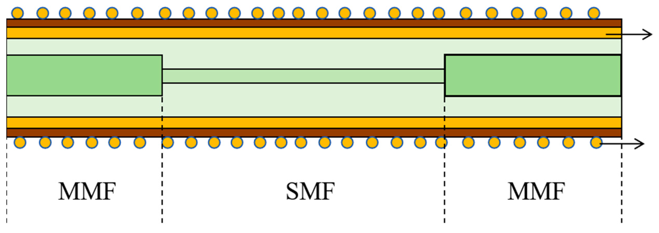
Studies have shown that the sensitivity achievable of a conventional gold-film SPR sensor is only 2057 nm/RIU with a quality factor of 20.21 RIU−1, which makes it difficult to meet the requirements of high-precision detection. The configuration of a conventional fiber SPR sensor is depicted in Figure 1.
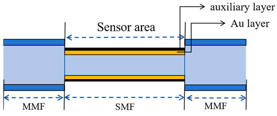
Figure 1.
Schematic structure of conventional fiber SPR sensor.
In general, a complete fiber sensing system consists of five parts, as shown in Figure 2: a light source, fiber optic jumper, fiber optic SPR biosensor, spectrometer, and computer. The basic operating principle involves light emitted from a source that travels through the fiber transmission to the detection region. The parameters to be measured and the light interact with the light signal intensity, wavelength, frequency, and phase, and other parameters change. The changed light signal is transmitted back to the fiber optic receiving subsystem, and through the calculation of the difference between the changes in the light signal, the measured parameters are mapped to complete the measurement.
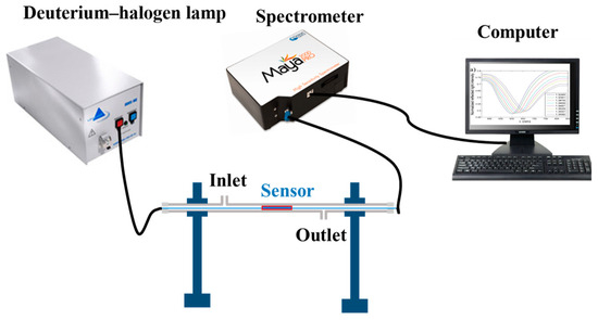
Figure 2.
Fiber optic sensing system.
SPR is an optical phenomenon that occurs at the surface between a metal and a medium. When an incident light wave reaches the interface between the metal layer and the dielectric layer, a small portion of the light wave enters the metal layer in the form of a fading wave at the same time as the light wave undergoes total reflection. If the evanescent wave incident on the metal layer meets the resonance conditions of the surface plasma wave, an SPR phenomenon will occur, and the part of the light wave energy that meets the resonance conditions will be converted into the oscillation energy of the SPW.
The principle of an SPR sensor for the detection of biomolecules involves a sensor metal membrane layer modified with a biorecognition function of the recognition membrane layer, so that when it is combined with the biomolecule to be measured, the refractive index of the medium around the sensing membrane layer will change, and the SPR can be detected by the amount of the drift of the resonance wavelength to obtain the information of the biomolecule. The technical parameters of a conventional fiber optic SPR biosensor are shown in Table 1.

Table 1.
Technical parameters of conventional fiber optic SPR biosensors.
A system analysis is the process of analyzing the functional perspective of a system; clarifying the functions of the system, its components, and the interactions between system components and supra-system components; and identifying the problems of the current system [14]. The connection between function and function, component and component, and component and function is identified through the system analysis method. The analysis of the functional system for the current conventional pure gold-film SPR fiber optic sensor yields that the components of the current system are the core, cladding, metal film layer, auxiliary film layer, evanescent wave, surface plasma wave, and recognition film layer. The supersystem components are the light, the solution to be measured, and biomolecules.
The main working mechanism of the sensor is that when the total reflection of light occurs in the fiber core, there will be a small portion of the fading wave transmitted into the cladding layer. At the same time, the surface plasma wave will be generated, and when the fading wave resonates with the plasma wave, the transmission spectra will appear in the trough. The wavelength corresponding to the trough is known as the resonance wavelength. When a biomolecule is adsorbed on the recognized membrane layer, variations in the refractive index of the solution under examination result in a shift in the resonance wavelength, thereby enabling the quantification of the biomolecule’s concentration.
According to the above principle, the comprehensive sensor system components are analyzed for their interactions, and the functional analysis picture of an engineered system is drawn, which can be seen in Figure 3. The system is analyzed to have the following functional defects: the fiber core has a loss in the transmission of light, the surface plasma wave intensity is low, the cladding layer has a loss in the transmission of evanescent waves, and the metal film layer cannot effectively adsorb the auxiliary film layer. For this reason, the above problems will be analyzed and solved later.
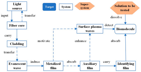
Figure 3.
Graphical representation of functional analysis of engineering systems.
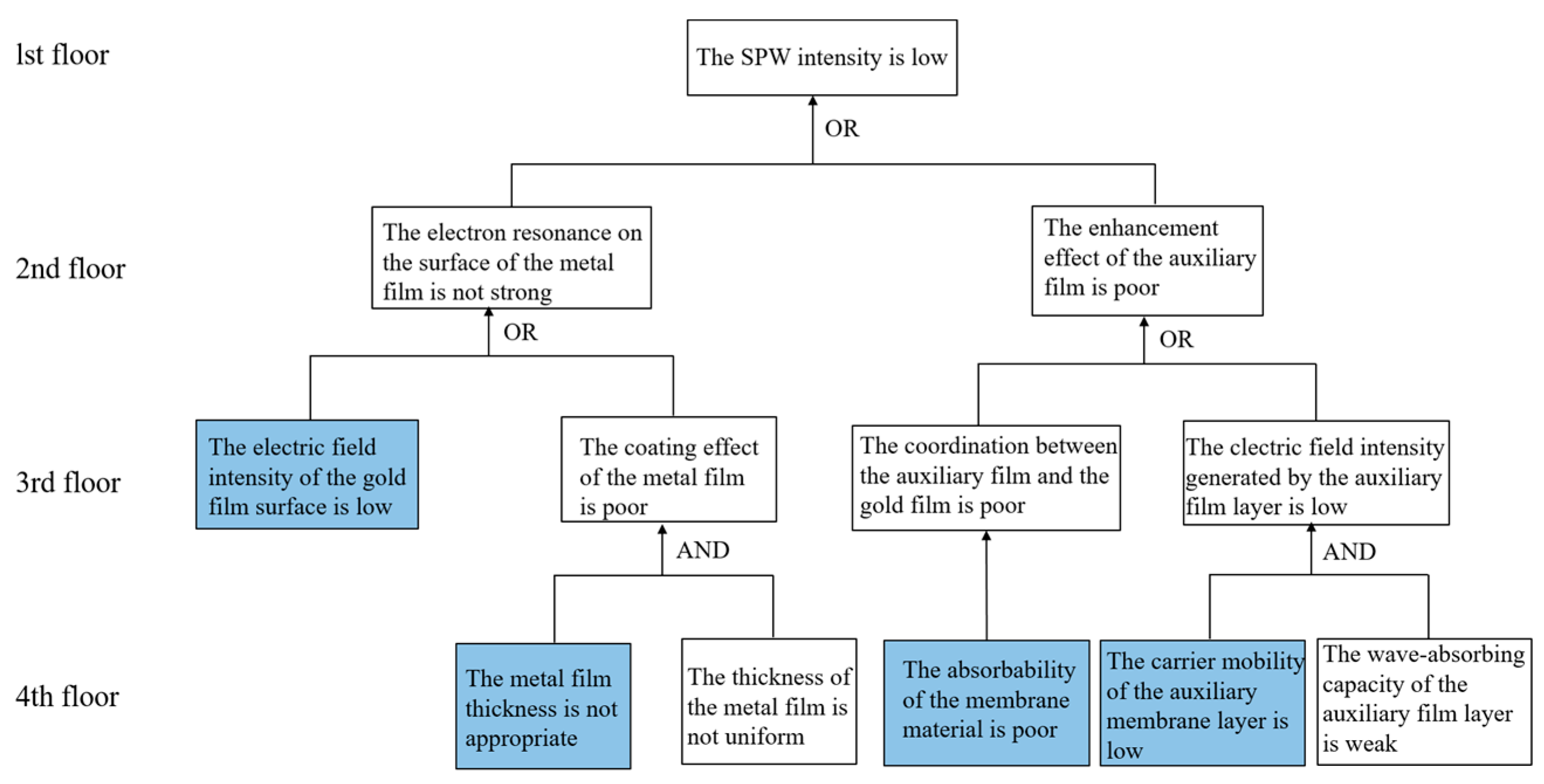
As an important tool for analyzing problems in the modern TRIZ, the purpose of a causal analysis is not to solve the initial shortcomings of the engineering system, but to find one or more root causes of the shortcomings of the engineering system and to provide a more in-depth analysis for solving the problems by digging out more shortcomings and reasons behind the initial shortcomings of the engineering system, so as to find breakthroughs for solving the problems [15,16,17]. Taking the defect of low surface plasma wave intensity obtained from the functional analysis as the initial shortcoming, it is found that “the electronic resonance on the surface of the metal film layer is not strong” and “the auxiliary film layer has a poor effect on the enhancement of this effect” are the causes of the “low surface plasma wave intensity”. We found that “weak surface electron resonance of the metal film layer” and “poor enhancement of the effect by the auxiliary film layer” are the main causes of “low surface plasma wave intensity”, and then we constructed a causal chain and identified four key drawbacks to be solved, as shown in Figure 4.
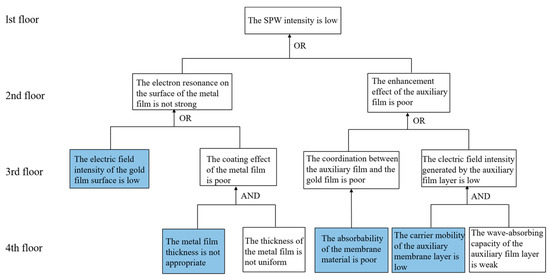
Figure 4.
Causal analysis diagram.
3. Results
3.1. Object-Field Analysis
To address the problem of inappropriate thickness of the gold film layer, solution 1 was given through simulation and experimental verification: the best performance of the sensor is achieved when the gold film’s thickness is set to 50 nm [18]. For the problem of poor adsorption of the membrane layer material, solution 2 is proposed: the membrane layer is coated on the fiber surface by mixing the membrane layer material with chitosan through layer-by-layer self-assembly to achieve effective adsorption. The resulting problems of the low electric field strength of the metal surface and the low carrier mobility of the auxiliary film layer will be solved by TRIZ tools.
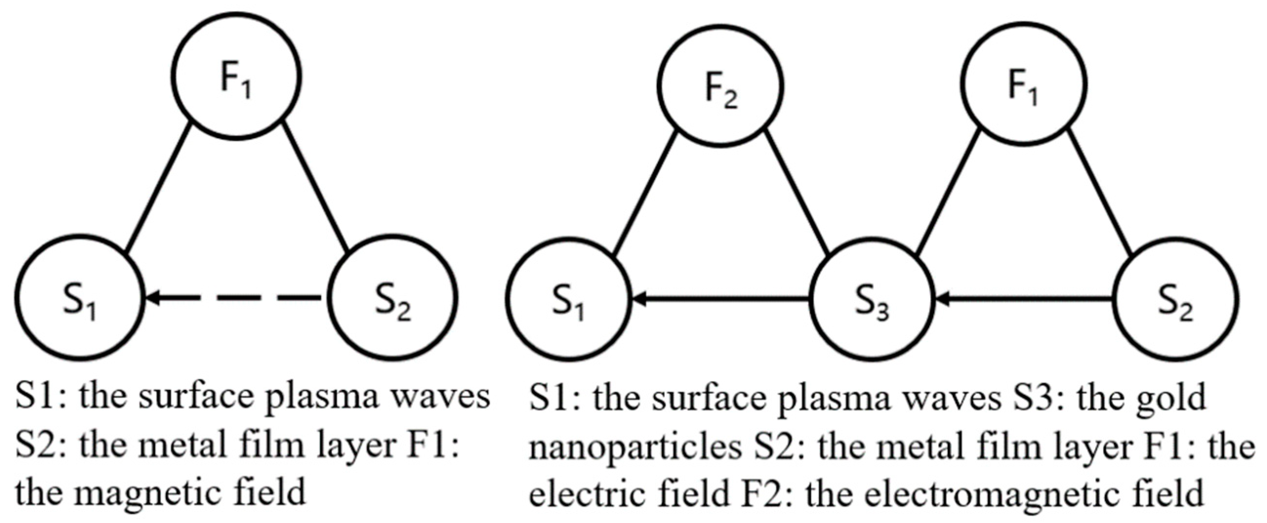
An object-field analysis is a method of presenting the functional relationships in a minimal technological system consisting of two substances and a field using the method shown in Figure 5, which is able to reveal the interrelationships such as underactivity, harmfulness, and overactivity that exist between the elements of a technological system and provides 76 standard solution schemes for solving these problems [19]. The surface plasma wave excited by the metal film layer is weak in intensity and belongs to the underactuated object field model. According to the type of standard solution, we found that the second type of standard solution is used to perfect the matter-field model. According to TRIZ standard solution S2.1.1 [17], Synthesis of Chained Object-Field Systems, the single matter-field model is transformed into a chained model (shown in Figure 5). The effect of enhanced surface plasma waves is realized by introducing substance S3, gold nanoparticles, allowing the field generated by the metal film layer (S2) to act on the gold nanoparticles (S3) and applying the electric field generated by the gold nanoparticles (S3) to the surface plasma waves (S1).
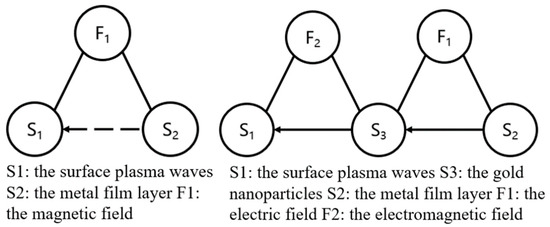
Figure 5.
Physical field model and its standard solution.
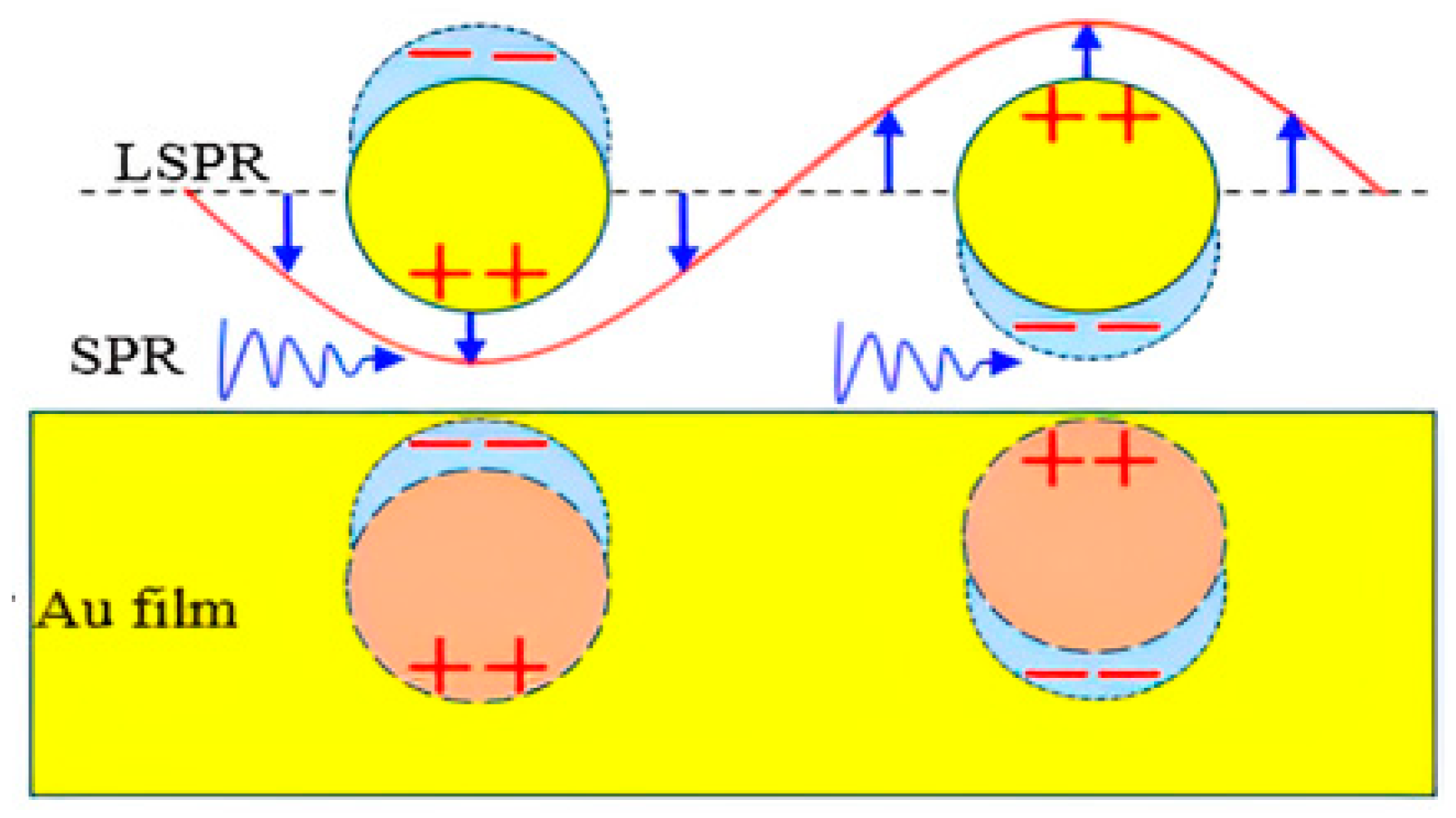
When the gold nanoparticles are fixed on the Au film, two types of plasma appear. The gold nanoparticles can be coupled with each other and between the nanoparticles and the gold film, resulting in an increase in local electric field strength, thereby improving sensitivity. We can better stimulate the SPR effect by adjusting the shape, length–diameter ratio, and arrangement rules of the gold nanoparticles.
This leads to solution 3: the introduction of gold nanoparticles and mirror coupling of the gold nanoparticles and gold film to enhance the surface plasma wave. The specific structure change schematic is shown in Figure 6.
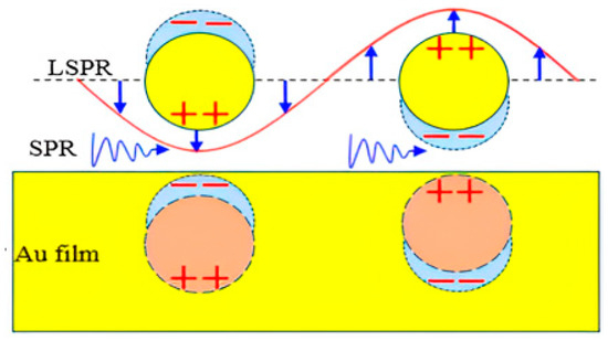
Figure 6.
Schematic diagram of structural changes.
3.2. HOW-TO Model and Knowledge Effects Library
From the object-field analysis, we can obtain the scheme of introducing gold nanoparticles, but in gold nanoparticles in the same available space, the specific surface area of the ball is small, resulting in a small coupling area between the metal film layer and the electric field of gold nanoparticles, and the coupling strength is small. To address this problem, the HOW-TO problem model is constructed, which is converted to the standard expression form of “how + verb + noun”. The operation type (verb) was chosen as “change” and the parameter (noun) as “shape”, i.e., “how to change the shape”. Accordingly, the knowledge effect library was searched, and the available corresponding scientific effects and phenomena were screened. Table 2 shows the scientific effects used in this study and their detailed explanations.
Table 2.
Scientific effects and their detailed explanations.
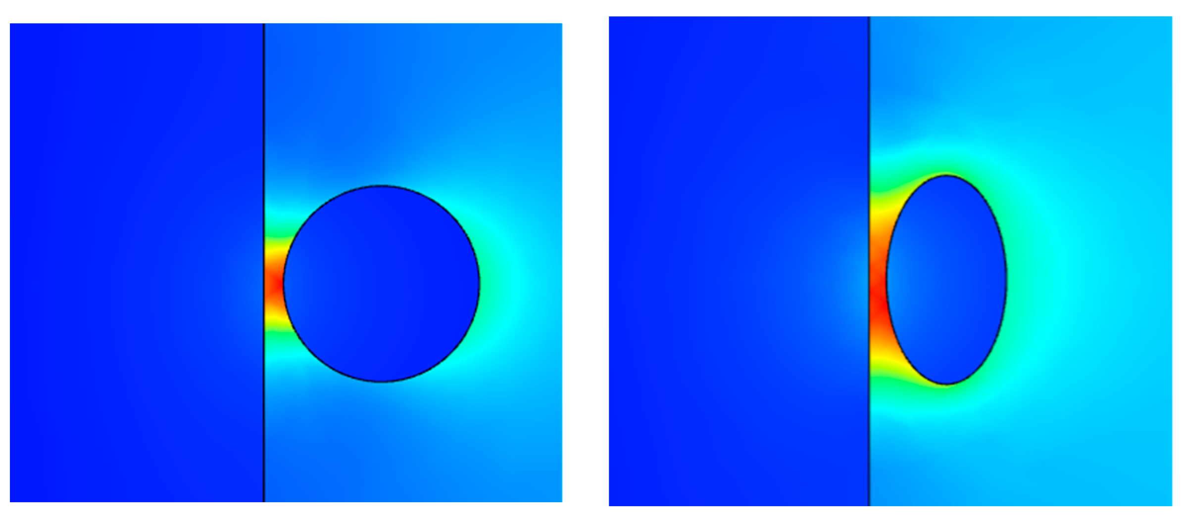
The above three scientific effects are applied to solve the problem, and the key to solving the problem is formed: the elongation–diameter ratio of ellipsoidal gold nanoparticles is continuously adjustable and has good stability, and the specific surface area is large. Thus, solution 4 is obtained: changing the shape of the gold nanoparticles to ellipsoidal by compression increases the specific surface area of the ball so that the electric field coupling region between the metal film layer and the gold nanoparticles increases, realizing an increase in the coupling strength. The aim is to verify the correctness in the above scheme. COMSOL simulation software was used to simulate and analyze the ellipsoidal-shaped gold nanoparticles to compare the strength of electric field coupling before and after the change, as shown in Figure 7. A comparison reveals that after changing the gold nanoparticles to ellipsoidal shape, the area of the red region increases, indicating that the strength of the coupled electric field increases.
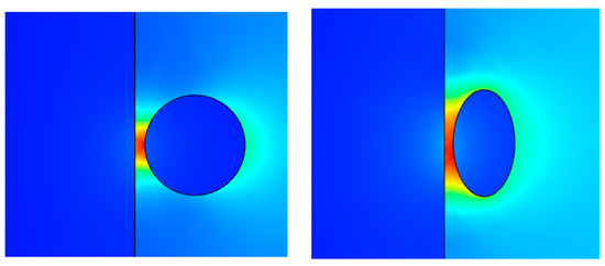
Figure 7.
Comparison of electric field strength of gold nanoparticles before and after shape change.
3.2.1. Physical Contradictions
Within a system, having sensible opposite demands for the same physical parameter of the same component is called a physical contradiction [20]. Analyzed by HOW-TO, the introduction of ellipsoidal gold nanoparticles, which can better enhance the surface electric field strength by utilizing their coupling with the gold film, also triggers a new physical contradiction: there is a physical contradiction conflict in the size of the ellipsoidal gold nanoparticle aspect ratio. The ellipsoidal gold nanoparticle aspect ratio needs to be large because it can increase the electric field coupling region; the ellipsoidal gold nanoparticle aspect ratio needs to be small because it can reduce the full width of the half peak and improve the accuracy. The physical contradiction is shown in Table 3.
Table 3.
Physical contradictions.
According to the TRIZ, five methods can be used to solve physical conflicts: temporal separation, spatial separation, relational separation, directional separation, and system level separation. The applicable inventive principles are recommended based on the separation methods [19].
Through the above analysis, it can be seen that there is also a crossover in the time domain, so the method of relational separation was chosen to solve the problem. According to the principle of “spatial dimension change” in relation separation, the layer number of the ellipsoidal gold nanoparticles can be changed so as to increase the field coupling region and prevent the full width of the half peak from increasing. This solves the problem that the aspect ratio of ellipsoidal gold nanoparticles is both large and small. Thus, solution 5 is obtained: adopt a double-layer ellipsoidal gold nanoparticle structure. As shown in Figure 8, the gold film is plated outside the sensing region of the multi-mode–single-mode–single-mode-structured fiber optic substrate, and double-layer gold nanoparticles are coated on the surface of the gold film.
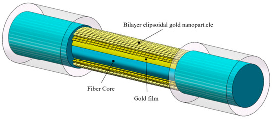
Figure 8.
Bilayer ellipsoidal gold nanoparticles.
3.2.2. The Villain Method of Analyzing and Solving
The TRIZ contains not only a large number of problem-solving tools, but also ways to break through the inertia of thinking, and the miniaturization method is one of them. As an effective carrier from the macro- to the micro-field, the miniaturization method uses several groups of dynamic miniatures to represent the completion of a specific functional component, and the structure is redesigned according to the miniaturization model to realize the expected function. To solve the problem of low carrier mobility in the auxiliary membrane layer in the functional analysis by simulation using the villain method, the following three villains are assumed to be gold particles, holes, and electrons.
Figure 9 demonstrates the distribution of electron migration before the sensor structure is adjusted, where the evanescent wave induces an inhomogeneity of charge distribution on the surface of the gold film, which excites surface plasmon polaritons (SPPs). However, it can be observed from the figure that the electron transfer phenomenon shown by the blue villain, which represents electron migration, is not obvious, which suggests that the strength of the excited surface plasmon polaritons is relatively weak under the current sensing structure.
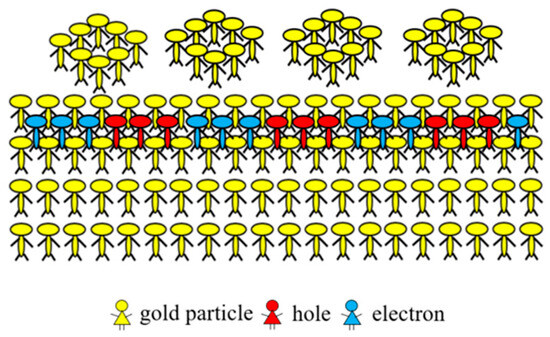
Figure 9.
Electron migration diagram before change.
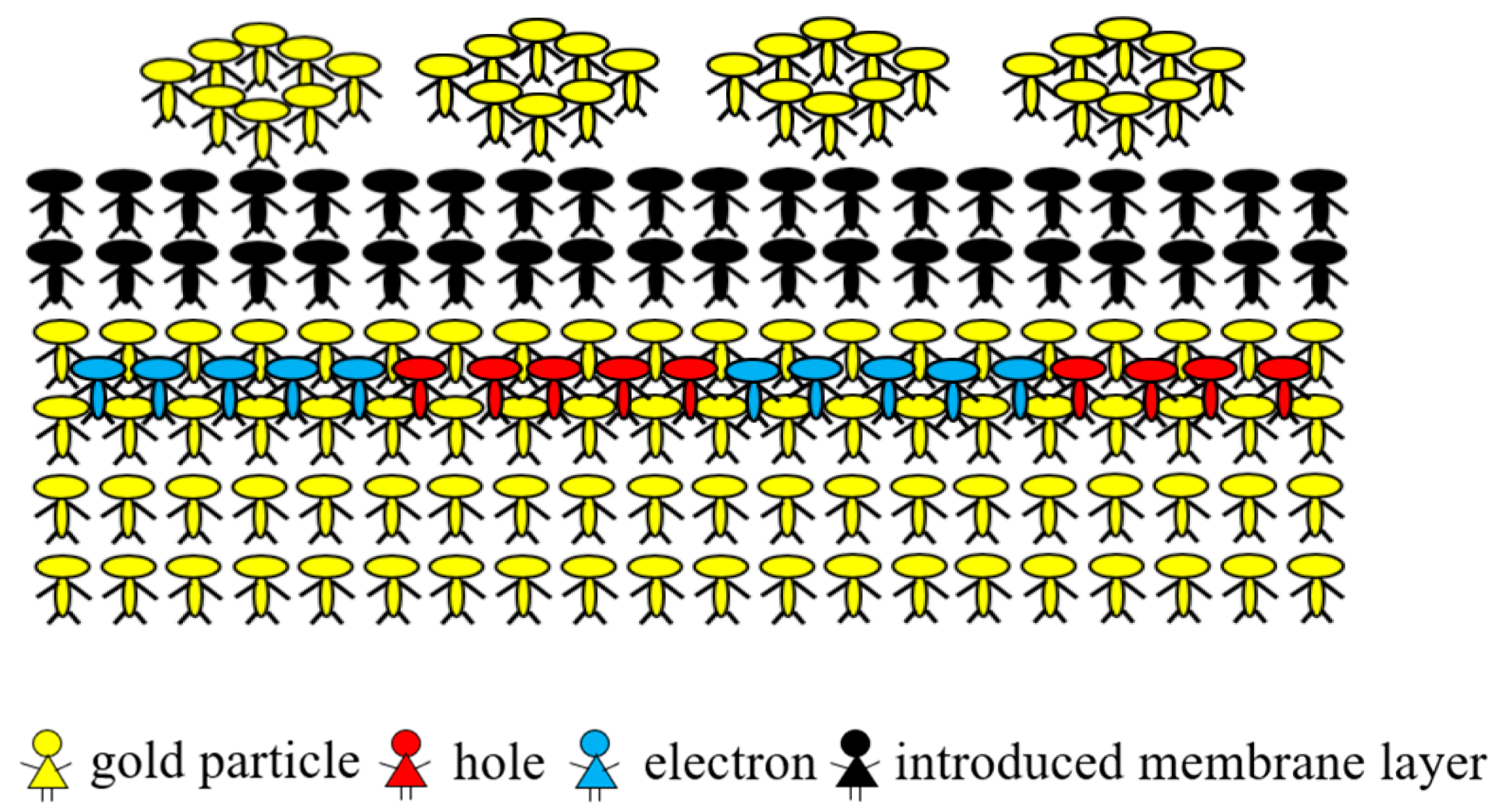
By applying the villain method to find a way to increase the strength of surface equipolarized excitations at the microscopic level, the introduction of the black villain a with high carrier mobility is attempted in order to boost electron transfer in the gold films. As shown in Figure 10, the introduction of the black villain greatly promotes the migration of the blue electron villain on the gold film, enhances the electric field strength of the gold film, and thus increases the surface equipolarized exciton strength greatly.

Figure 10.
Electron migration diagram for the introduction of the black villain.
Checking the related literature, we found a new material with high carrier mobility, molybdenum disulfide, and obtained solution 6: enhance the transfer of electron villains by coating a new optical material, molybdenum disulfide, on the gold film. The high carrier mobility of molybdenum disulfide can significantly boost the transfer of electrons on gold film, which is conducive to the enhancement of surface equipolarized excitations [20]. The rich functional groups on its surface enable chemical bonding between the gold film and the gold nanoparticles, resulting in a more stable structure.
4. Discussion
As can be seen from Table 4, by combining solutions 1, 2, 3, and 6, we obtain the new fiber SPR sensor structure, as shown in Figure 11. A multimode–single-mode–multimode structure of the SPR sensor was fabricated by a fiber optic fusion splicer. The sensing region of the sensor was composed of 5 mm single-mode fibers, and the length of the multimode fibers at both ends was 10 mm. A small ion sputtering instrument (SAINTINS JS-1600, Nanjing, China) was used for the preparation of the gold film on the surface of the sensing region. Based on the experimental experience and parameter optimization, the optimal sputtering parameters were determined: under the conditions of a steady 8 mA discharge current and an 80 s duration, the resulting thickness of the gold film deposited via sputtering was approximately 50 nanometers. This thickness of the gold film provides ideal optical properties for the surface plasmon resonance (SPR) sensors, which can help to achieve a high sensitivity sensing effect.
Table 4.
Analytical evaluation of programs.
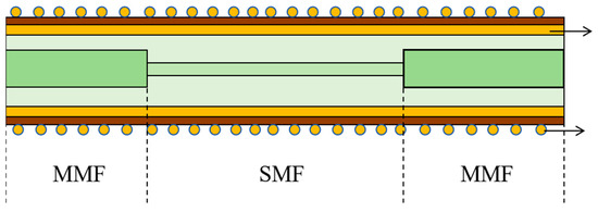
Figure 11.
New SPR sensor.
The coating of the molybdenum disulfide film layer on the surface of the gold film was carried out as described below. First, 500 mg of chitosan powder was measured out and transferred into a 50 mL solution of 4% glacial acetic acid. The mixture was then continuously agitated for 15 min until the chitosan was fully dissolved. An amount of 3 mL of the chitosan solution was aliquoted into a diminutive beaker. Subsequently, 5 mL of a molybdenum disulfide (MoS2) nanosheet dispersion was introduced into the chitosan solution. The resultant mixture was then subjected to ultrasonic treatment for a duration of 23 min. This process facilitated the formation of a homogeneous MoS2 nanosheet dispersion characterized by a positive surface charge. The sensing region of the sensor with the sputtered gold film was immersed in a 5 mg/mL PSS solution for a period of 3 min. Upon completion of this immersion, the substrate was subsequently exposed to ambient air for an additional 10 min. This resulted in a negative charge on the surface of the sensing region that had been sputtered with gold film. The PSS-processed sensor was secured to an elevated coating apparatus, and a positively charged molybdenum disulfide (MoS2) nanosheet dispersion, which had been modified with chitosan, was applied to the gold film’s surface. After coating, the molybdenum disulfide coating was finalized after the sensor was exposed to air for a period of 24 h. The coated molybdenum disulfide sensor was then immersed into a 2 mmol/L ethanol solution of p-aminothiophenol for 30 min before the sensor was removed and dried, thus fixing the surface with p-aminothiophenol. The sensor was immersed for six hours in a gold nanoparticle dispersion, which was a liquid solution containing gold nanoparticles that were evenly dispersed in the liquid to form a stable dispersion. This allowed the gold nanoparticles to be more evenly fixed to the surface of the sensor, which could be dried to complete the fabrication of the sensor.
In addition to this, a sensor with a 50 nm pure gold film was fabricated as the control with a new sensor, and a sensing system consisting of a light source, a sensor, a spectrometer, and a computer was built for refractive index experiments. The sensors were treated with a NaCl solution, which spanned a range of the refractive index from 1.33 to 1.37, and the transmission spectra were recorded. The sensitivity was solved by the following equation:
S represents the sensor’s sensitivity, which is indicative of the shift in the resonance wavelength () in response to variations in the medium’s refractive index ().
The FOM (Figure of Merit) affects the detection accuracy and can be calculated using the following formula:
where S is the sensitivity and FWHM is the full width at half maximum.
The refractive index experiments were performed on the fabricated novel sensor, its transmission spectrum was measured and linearly fitted, and the sensor’s transmission spectrum along with its corresponding sensitivity fitting curve are depicted in Figure 12.
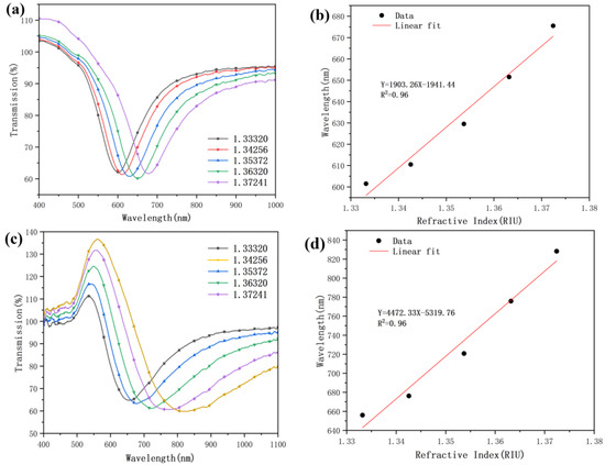
Figure 12.
Transmission spectra and sensitivity fit curves (a); (b) 50 nm gold film SPR sensor (c); (d) novel sensor.
As can be seen in Figure 12, the gold-film-based sensor, with a thickness of 50 nm, exhibits a sensitivity value of 1903.26 nm/RIU and an FOM of 19.06 RIU−1. The sensitivity of the novel sensor coated with molybdenum disulfide and gold nanoparticles reaches 4472.33 nm/RIU, which is a 135% increase in sensitivity compared with the pure gold film sensor. The FOM of the novel sensor is increased to 29.23 RIU−1, an increase of 53.36% compared to the pure gold film sensor. The results show that the performance of the novel optical fiber SPR sensor designed by the TRIZ is significantly improved compared to that of the sensor using the gold film. Due to the ultra-high carrier mobility of molybdenum disulfide at room temperature, the electron migration in the gold film is effectively promoted, and the sensitivity is significantly improved. In addition, the scheme proposed by the TRIZ is proven: the introduction of gold nanoparticles coupled with the gold film can effectively enhance the surface plasma wave and significantly improve the sensitivity of the sensor. This sensor demonstrates enhanced sensitivity and holds significant promise for applications in the realms of early-stage disease detection and clinical medicine.
5. Conclusions
This paper presents a functional and causal analysis of a conventional gold film SPR sensor based on the TRIZ with the aim of identifying and solving key problems in the current system. Through this methodology, the key factors affecting the performance of the sensor are successfully identified. A series of innovative solutions are proposed by applying typical TRIZ tools to address the key issues of low sensitivity and the quality factor of conventional fiber optic SPR sensors. These solutions aim to optimize the structural design and material selection of the sensor to improve its sensing performance. The experimental validation results show that the novel sensor solutions proposed based on the TRIZ have the advantages of high sensitivity and high stability and have great application prospects in the field of low-concentration bio-detection. By combining the TRIZ with experimental research, we not only improve the performance of the fiber SPR sensor but also provide new ideas and methods for the development of future sensor technology.
Author Contributions
Conceptualization, C.-l.Z. and J.-d.L.; data curation, F.W.; formal analysis, C.-l.Z.; investigation, F.W.; methodology, C.-l.Z.; resources, C.-l.Z. and F.W.; supervision, F.W.; validation, C.-l.Z. and J.-d.L.; writing—original draft, J.-d.L.; writing—review and editing, C.-l.Z. and J.-d.L. All authors have read and agreed to the published version of the manuscript.
Funding
This research received no external funding.
Institutional Review Board Statement
Not applicable.
Informed Consent Statement
Not applicable.
Data Availability Statement
The data presented in this study are available on request from the corresponding author.
Conflicts of Interest
The authors declare no conflicts of interest.
References
- Zhao, Y.; Tong, R.-J.; Xia, F.; Peng, Y. Current status of optical fiber biosensor based on surface plasmon resonance. Biosens. Bioelectron. 2019, 142, 111505. [Google Scholar] [CrossRef]
- Pandey, P.S.; Raghuwanshi, S.K.; Shadab, A.; Ansari, M.T.I.; Tiwari, U.K.; Kumar, S. SPR Based Biosensing Chip for COVID-19 Diagnosis—A Review. IEEE Sens. J. 2022, 22, 13800–13810. [Google Scholar] [CrossRef]
- Shan, B.-H.; Kong, L.-X.; Wu, K.-J.; Ou, S.-F.; He, P.-F.; Jin, G.; Li, Z.; Zhang, Y.-S. High sensitivity and ultra compact fiber-optic microtip SPR thermometer coated with Ag/PDMS bilayer film. Opt. Fiber Technol. 2021, 65, 102619. [Google Scholar] [CrossRef]
- Balbinot, S.; Srivastav, A.M.; Vidic, J.; Abdulhalim, I.; Manzano, M. Plasmonic biosensors for food control. Trends Food Sci. Technol. 2021, 111, 128–140. [Google Scholar] [CrossRef]
- Chauhan, M.; Singh, V.K. Review on recent experimental SPR/LSPR based fiber optic analyte sensors. Opt. Fiber Technol. 2021, 64, 102580. [Google Scholar] [CrossRef]
- Shalabney, A.; Abdulhalim, I. Sensitivity-enhancement methods for surface plasmon sensors. Laser Photonics Rev. 2011, 5, 571–606. [Google Scholar] [CrossRef]
- Chen, Y.; Xie, Q.; Li, X.; Zhou, H.; Hong, X.; Geng, Y. Experimental realization of D-shaped photonic crystal fiber SPR sensor. J. Phys. D Appl. Phys. 2016, 50, 025101. [Google Scholar] [CrossRef]
- Zhang, C.; Jiang, S.Z.; Li, C.H.; Xu, S.C.; Yu, J.; Li, Z.; Wang, M.H.; Liu, A.H.; Man, B.Y. U-bent fiber optic SPR sensor based on graphene/AgNPs. Sens. Actuators B Chem. 2017, 251, 127–133. [Google Scholar] [CrossRef]
- Chopra, A.; Mohanta, G.C.; Das, B.; Bhatnagar, R.; Pal, S.S. Tuning the sensitivity of a fiber-optic plasmonic sensor: An interplay among gold thickness, tapering ratio and surface roughness. IEEE Sens. J. 2021, 21, 12153–12161. [Google Scholar] [CrossRef]
- Singh, S.; Mishra, S.K.; Gupta, B.D. Sensitivity enhancement of a surface plasmon resonance based fibre optic refractive index sensor utilizing an additional layer of oxides. Sens. Actuators A Phys. 2013, 193, 136–140. [Google Scholar] [CrossRef]
- Wang, Q.; Niu, L.-Y.; Jing, J.-Y.; Zhao, W.-M. Barium titanate film based fiber optic surface plasmon sensor with high sensitivity. Opt. Laser Technol. 2020, 124, 105899. [Google Scholar] [CrossRef]
- Rahman, M.S.; Noor, S.S.; Anower, M.S.; Abdulrazak, L.F.; Rahman, M.M.; Rikta, K.A. Design and numerical analysis of a graphene-coated fiber-optic SPR biosensor using tungsten disulfide. Photonics Nanostruct.-Fundam. Appl. 2019, 33, 29–35. [Google Scholar] [CrossRef]
- Alagdar, M.; Yousif, B.; Areed, N.F.; Elzalabani, M. Highly sensitive fiber optic surface plasmon resonance sensor employing 2D nanomaterials. Appl. Phys. A 2020, 126, 522. [Google Scholar] [CrossRef]
- Yao, W.; Wang, C.; Pang, J.; Liu, Y.; Zhang, J. Research and development of fully enclosed wire-shell support structure technology for deep soft rock roadway based on TRIZ theory. Sci Rep. 2024, 14, 3279. [Google Scholar] [CrossRef] [PubMed]
- Huan, Y.; Luan, F. Design of apple sorting and bagging device based on TRIZ theory. Mech. Des. 2021, 38, 104–107. [Google Scholar]
- Wang, J.H.; Feng, H.X.; Tan, L.; Chen, N.L.; Zhao, D.; Shi, L.L.; Zhang, H.X. Application of TRIZ theory in improving the corrosion resistance of oil rig coatings. Packag. Eng. 2021, 45, 299–306. [Google Scholar]
- Xiao, J.; Liu, F.; Yang, M.; Ke, W.; Liu, D.; Lin, L. An innovative design of mega shaft boring machine (SBM) cutterhead based on TRIZ and AD theory. Adv. Mech. Eng. 2023, 15, 16878132231153358. [Google Scholar] [CrossRef]
- Chechurin, L.; Borgianni, Y. Understanding TRIZ through the review of top cited publications. Comput. Ind. 2016, 82, 119–134. [Google Scholar] [CrossRef]
- Wang, Z.; Mi, B. Environmental Applications of 2D Molybdenum Disulfide (MoS2) Nanosheets. Environ. Sci. Technol. 2017, 51, 8229–8244. [Google Scholar] [CrossRef] [PubMed]
- Nangare, S.; Patil, P. Chitosan mediated layer-by-layer assembly based graphene oxide decorated surface plasmon resonance biosensor for highly sensitive detection of β-amyloid. Int. J. Biol. Macromol. 2022, 214, 568–582. [Google Scholar] [CrossRef] [PubMed]


Disclaimer/Publisher’s Note: The statements, opinions and data contained in all publications are solely those of the individual author(s) and contributor(s) and not of MDPI and/or the editor(s). MDPI and/or the editor(s) disclaim responsibility for any injury to people or property resulting from any ideas, methods, instructions or products referred to in the content. |
© 2024 by the authors. Licensee MDPI, Basel, Switzerland. This article is an open access article distributed under the terms and conditions of the Creative Commons Attribution (CC BY) license (https://creativecommons.org/licenses/by/4.0/).