Article

Joint Constellation and Reflectance Optimization for Tunable Intelligent Reflecting Surface-Aided VLC Systems

The School of Electronic and Optical Engineering, Nanjing University of Science and Technology, Nanjing 210094, China
*
Author to whom correspondence should be addressed.
Photonics 2024, 11(9), 840; https://doi.org/10.3390/photonics11090840
Submission received: 14 August 2024 / Revised: 2 September 2024 / Accepted: 3 September 2024 / Published: 5 September 2024

Abstract

:
The intelligent reflecting surface (IRS) is an emerging technology that can conquer visible light communication’s (VLC) dependency on the line-of-sight (LoS) channel by offering additional non-light-of-sight (NLoS) communication links. In this paper, a newly proposed electro-tunable intelligent reflecting metasurface is deployed in dimmable single-input single-output (SISO) VLC systems. We aim to improve the bit error rate (BER) performance by jointly optimizing the transmit constellation and the reflectance of the IRS units. To this end, the optimization problem can be solved in two steps. The minimum distance of the received constellation is firstly maximized by a convex problem, which guarantees the minimum BER. Then, the transmit constellation and the synchronously-tunable reflectance of the IRS units that correspond to the optimal received constellation are determined with an iterative alternate optimization algorithm. Finally, the simulation results show the BER performance improvement and the dimming relaxation benefit of the tunable IRS-aided SISO VLC systems.

1. Introduction

The development of sixth-generation (6G) communication imposes a thousand-fold increase in the traffic volume for wireless networks in the foreseeable future. Visible light communication (VLC) is a significant supplement technology used to release the pressure of the crowded radio frequency resource due to its advantages, including high transmission speed, license-free spectrum, high physical layer security, ubiquitous light-emitting diodes (LEDs) transmitters, and free radio frequency (RF) interference [1]. However, VLC’s high dependency on the line-of-sight (LoS) channel and illumination demand limit its further deployment and industrialization. Optical intelligent reflecting surfaces (IRSs) have recently emerged as a revolutionary technology to enhance the performance of VLC by providing additional non-line-of-sight (NLoS) communication links [2,3].
In particular, an IRS is a novel planar material that is able to improve the wireless channel gain by interacting with incident electromagnetic waves [4]. Plenty of studies have been conducted to improve the performance of RF wireless communication systems by introducing an IRS [5,6,7]. It has been shown that the data rate performance of IRS-aided multiple-input multiple-output (MIMO) systems was comparable to that of massive MIMO systems [5]. Moreover, a channel acquisition approach for IRS-aided multiuser MIMO systems was proposed in [6]. And the IRS was deployed to improve the dirty-paper coding (DPC) sum rate in the IRS-assisted broadcast channels [7].
Mirror arrays and metasurfaces are two mainstream IRS units for VLC systems [8]. Mirror arrays control the lightwave propagation by rotating the planar micro-mirrors based on Snell’s law of reflection [2]. Since the reflectance of the micro-mirror cannot be changed, most IRS-aided VLC systems with mirror arrays focus on the micro-mirrors’ associations with users or LEDs. For example, the micro-mirror’s associations and LED’s transmit power are jointly optimized to improve the spectral efficiency in multiuser IRS-aided VLC systems [1]. The mean square error is minimized by jointly designing the IRS configuration and the transceiver signal processing in IRS-aided MIMO VLC systems [9]. The sum rates of the IRS-aided VLC system were maximized by optimizing the micro-mirror’s associations with users and the mirrors’ orientation in [10] and [11], respectively.
The mirror-based optical IRS unit is a kind of passive reflecting surface that can change the direction of light rays of the VLC signal only, while an active IRS unit can change the signal amplitude or power with equipped amplifiers [12]. Optical metasurfaces are artificial planar structures capable of manipulating the wavelength, polarization, and phase of the incident wave by electrical management, and thus can realize anomalous reflection based on the generalized Snell’s law of reflection [8]. In [13], a newly developed polarization-insensitive electro-tunable metasurface was deployed for optical intensity modulation, and a modulation bit rate of up to 900 Mbps can be achieved by changing the reflectances of the IRS units in terms of its electro-optic properties. This newly proposed metasurface can be regarded as a kind of active optical IRS unit and adds design degrees of freedom to the IRS-aided VLC channels employing the intensity modulation and direct detection (IM/DD) scheme.
Motivated by this tunable reflective materials, we investigate the bit error rate (BER) performance improvement by jointly optimizing the pulse amplitude modulation (PAM) constellation and the coherent IRS reflectances in IRS-aided single-input single-output (SISO) VLC systems in this paper. The main contributions of this paper are listed as follows:
  • A newly IRS-aided SISO VLC system under dimming constraints is investigated with a metasurface-based IRS for which its reflectance can be synchronously tuned with the LED’s emitting signals.
  • The joint PAM constellation and reflectance optimization problem is formulated by maximizing the minimum distance between any two adjacent received constellation points to achieve better BER performance.
  • The optimization problem is solved in two steps. In step one, we solve a convex optimization problem for the optimal received constellation. In step two, a feasible problem is decomposed into two alternative optimizing sub-problems to find the transmit constellation and IRSs’ reflectances corresponding to the optimal received constellation.
  • The BER performance is shown and analyzed in terms of the BER curves and the constellation distributions. The extra dimming constraint relaxation benefit of the tunable IRS are illustrated compared with the mirror-based IRS.
The rest of this paper is organized as follows. In Section 2, the tunable IRS-aided SISO VLC system model is introduced, and the joint constellation and reflectance optimization problem is formulated. In Section 3, we propose a two-step algorithm to solve the optimization problem. Numerical results are provided in Section 4, and Section 5 concludes the paper.

2. System Model and Problem Formulation

2.1. System Model

Consider a SISO VLC system with K tunable IRS units employing the IM/DD scheme, as depicted in Figure 1. The reflectance of the IRS units, denoted by r = ( r 1 , , r K ) , can be modulated coherently by the central control unit (CCU) with the transmit signal. The VLC signal, represented by X, is emitted from the LED and travels to the photo-detector (PD) receiver through the LoS channel, the IRS reflected NLoS channels and the diffusely reflected NLoS channels. We ignore the diffusely reflected NLoS channels due to its negligible gain [1], so the received signal is formulated as
Y = ( h L + r T h N L ) X + Z ,
where h L is the direct channel (DC) gain of the LoS link, which can be calculated according to the geometric positions of the transceivers [8],
h L = A P ( m + 1 ) 2 π d L 2 cos m ( θ ) T s ( ψ ) g ( ψ ) c o s ( ψ ) , 0 ψ Ψ c 0 , Otherwise
where A P is the area of the PD, and d L is the distance between the LED and the PD. θ is the angle of irradiance, and m = 1 / log 2 ( cos ( Θ 1 / 2 ) ) is the Lambertian radiation index, where Θ 1 / 2 is the half radiation angle; ψ is the angle of incidence; Ψ c is the semi-angle of the field of view (FoV); g ( ψ ) is the optical filter gain; and T s ( ψ ) is the optical concentrator gain, which can be calculated by
T s ( ψ ) = n 2 sin 2 Ψ c 0 ψ Ψ c 0 Otherwise ,
where n is the refractive index.
h N L = ( h 1 N L , , h K N L ) represents all of the IRS-reflected NLoS path loss without reflection loss, where h k N L can be calculated by [8]
h k N L = A P ( m + 1 ) cos m ( θ R k S ) 2 π ( R k S 2 + R k D 2 ) 2 cos ( θ R k D ) cos ( θ R k , D M S ) N k T ^ R k D ^ T s ( cos ( θ R k D ) ) g ( cos ( θ R k D ) ) , 0 θ R k D Ψ c 0 , Otherwise
where, R k S 2 and R k D 2 represent the distances from the k-th IRS unit to the LED (S) and the PD (D), respectively. θ R k S is the angle of irradiance from the LED to the k-th IRS unit. θ R k , D M S is the angle of irradiance from the k-th IRS unit to the PD, where N ^ k T represents the unit normal vector of the k-th IRS unit. θ R k D is the angle of incidence from the k-th IRS unit to the PD. R k D ^ is the unit vector from the k-th IRS unit to the PD. Thus, r T h N L is the IRS reflected channel gain. Z N ( 0 , σ 2 ) is the additive white Gaussian noise.
Due to LEDs’ lighting property, real-valued signals are modulated on the intensity of the LED light, so a non-negative constraint and a peak intensity constraint are imposed on the amplitude as
0 X A ,
where A is the peak light intensity of the LED. The actual perceived illumination intensity of human eyes depends on the expectation of X, which is supposed to be adjusted according to the user’s dimming requirement:
E [ X ] = ξ A ,
where 0 ξ 1 is the dimming coefficient.

2.2. Problem Motiviation

For optical wireless communication systems using LEDs or laser diodes (LDs) as transmitters, an IM/DD scheme is adopted. The intensity of the emitting light is modulated according to the transmitted signals [14]. On–Off keying (OOK) is a commonly used binary modulation scheme. Since its modulation efficiency is unsatisfactory, higher-order modulation schemes, such as PAM or PPM (pulse position modulation) are adopted in pursuit of higher data rates. However, PPM requires higher synchronization accuracy and wider bandwidth. Therefore, we focus on the constellations of PAM in this paper.
As PAM is widely used in intensity-modulated VLC systems [15], the BER performance with the tunable IRS is optimized given the practical consideration of both communication and illumination. Without loss of generality, the normalized vector representation for the M-PAM constellation points is s = ( s 1 , s 2 , , s M ) , assuming that 0 s 1 s 2 s M 1 . All constellation points are transmitted with equal probability 1 / M . Let r m = ( r m , 1 , , r m , K ) denote the coherent reflectance vector of the IRS units when s m is transmitted, where r m , k denotes the reflectance of the k-th IRS for s m . The coherent reflectances for all constellation points are represented by r ¯ = ( r 1 , r 2 , , r M ) .
It was shown in [16] that the symbol error rate (SER) of AWGN channels is dominated by the distance between the most nearest received constellation points. Because PAM constellation points are one-dimensional and labeled by gray encoding, mistaking a symbol for an adjacent one in demodulation causes a single bit error only. As such, the BER performance is dominated by the minimum neighboring distance of the received signal constellations. Therefore, we aim to maximize the minimum distance between adjacent received constellation points to achieve better BER performance:
P : max s , r ¯ min m 1 s m s m 1 ,
s . t . s m = ( h L + r m T h N L ) s m ,
1 M 1 T s = ξ ,
0 s 1 s 2 s M 1 ,
0 r m , k γ ,
where s m = ( h L + r m T h N L ) s m is the received constellation point if s m is transmitted. s = ( s 1 , , s M ) denotes the received constellation vector. 1 is an M-dimensional vector of all ones, so (9) indicates the dimming constraint of equal-probability constellation points. γ is the maximum reflectance of the IRS.

3. Proposed Optimization Algorithm

As previously mentioned, it is the received constellation distribution that has significant impact on the BER performance, which rests with both the transmit constellation and the reflectance vector. This section proposes a two-step algorithm to optimize both the transmit constellation and the coherent reflectance vector:
  • Solve for the optimal received signal constellation s .
  • Find the transmit constellation points s and the coherent reflectance vector r ¯ corresponding to the optimal received constellation points.

3.1. Received Constellation Optimization

In taking the received constellation s as the optimization variable, optimization problem (7) is reorganized as
( P 1 ) max s f ( s ) = min m 1 s m s m 1 ,
s . t . h L ξ 1 M 1 M T s ( h L + γ 1 M T h N L ) ξ ,
0 M s ( h L + γ 1 M T h N L ) 1 M ,
C s 0 M ,
where 0 M is an M-dimensional vector of all zeros, and 1 M is all ones. (13) is the constraint on the expectation of the received constellation vector. (14) denotes the boundaries for the received constellation s . (13) and (14) are deduced by (8), (9), and (11), as shown in Appendix A. (15) is the vector representation of s 1 s 2 s M , where C is a circulant matrix,
C = 1 1 0 0 1 1 0 1 1 ( M 1 ) × M .
As all the constellation distances are non-negative, the minimum distance equals
f ( s ) = max m = 2 M s m s m 1
= 1 β log ( e β s 2 s 1 + + e β s M s M 1 ) ,
where the logsumexp function in (17) is a differentiable approximation of the max function, and β is a constant parameter affecting the convergence rate and the quality of approximation [17]. The concavity of the minus norm function in (16) makes (12) a convex optimization problem with affine constraints. The logsumexp function in (17) is also convex with a non-negative gradient. Thus, the optimal received constellation vector, assumed as s , can be solved with the gradient descent algorithm or other off-the-shelf optimization toolkits [17].

3.2. Joint Transmit Constellation and Reflectance Optimization

In the following, if we find the transmit constellation s and the coherent reflectance vector r ¯ that associated with the optimal received constellation s , then the original problem (7) is solved. This feasible problem can be written as
( P 2 ) F i n d s , r ¯ ( H r ¯ + 1 ) s = s s . t . ( 9 ) , ( 10 ) , ( 11 )
where ⊙ represents the Hadamard product (element-wise product), and H is a block diagonal matrix:
H = 1 h L h N L T 0 0 0 h N L T 0 0 0 h N L T M × ( M K ) .
(P2) indicates a constrained system of nonlinear equations, where the decision variables s and r ¯ are coupling in (18). Thus, we decompose (P2) into two sub-problems: (P2a) the coherent reflectance vector-solving problem given s and (P2b) the transmit constellation-solving problem given r ¯ .
( P 2 a ) S o l v e r ¯ diag ( s ) H r ¯ = s s , s . t . ( 11 ) , ( P 2 b ) S o l v e s diag ( H r ¯ + 1 ) s = s , s . t . ( 9 ) , ( 10 ) .
where diag ( · ) diagonalizes the vector in parentheses. Both (P2a) and (P2b) are groups of linear equations with constraints. (P2a) is an underdetermined system of linear equations that leads to non-unique solutions. The matrix diag ( H r ¯ + 1 ) in (P2b) is of full rank, so there is only one optimal solution at most.
To avoid the solution selection of (P2a) and the no-solution condition of (P2b), both (P2a) and (P2b) are relaxed as least-square problems:
( P 2 aR ) min r ¯ diag ( s ) H r ¯ s + s , s . t . ( 11 ) ( P 2 bR ) min s diag ( H r ¯ + 1 ) s s , s . t . ( 9 ) , ( 10 ) .
Under the condition of zero least squares, the relaxed problems are equivalent to the original ones.
As such, (P2) can by solved by alternatively solving relaxed sub-problems (P2aR) and (P2bR) with an initialized s satisfying (9), (10), and (11). After convergence, if the output couple of r ¯ and s is a feasible solution of (P2), (18) is solved. Otherwise, it can be rerun from a different initial s until (P2) is solved. The optimal received constellation s is obtained by solving (12) with constraints (13), (14), and (15), which guarantees the solvability of (P2).
The two-step joint constellation and reflectance optimization algorithm is illustrated in Algorithm 1. The relaxed least square problems with constraints can be solve using the lsqlin function in Matlab or scipy.optimize.minimize function in Python. Because problems (P1), (P2aR), and (P2bR) are simple convex problems with linear constraints, the proposed algorithm can be solved with polynomial complexity.
Algorithm 1 Joint Constellation and Reflectance Optimization Algorithm
Input:  M : modulation order ξ : the dimming coefficient
Step1: Slove for s by (P1)
Step2:
While: 1
Initialize: s satisfying (9), (10), and (11).
Do:
  Calculate r ¯ by (P2aR);
  Calculate s by (P2bR);
Until:  r ¯ and s are converged
if: The converged ( r ¯ , s ) is a feasible solution of (P2);
   Break;
  endif
  End While
Return:  r ¯ , s , s

4. Numerical Results

The BER performance and optimized received constellation of the tunable IRS-aided VLC links are shown and analyzed.

4.1. Simulation Scenarios
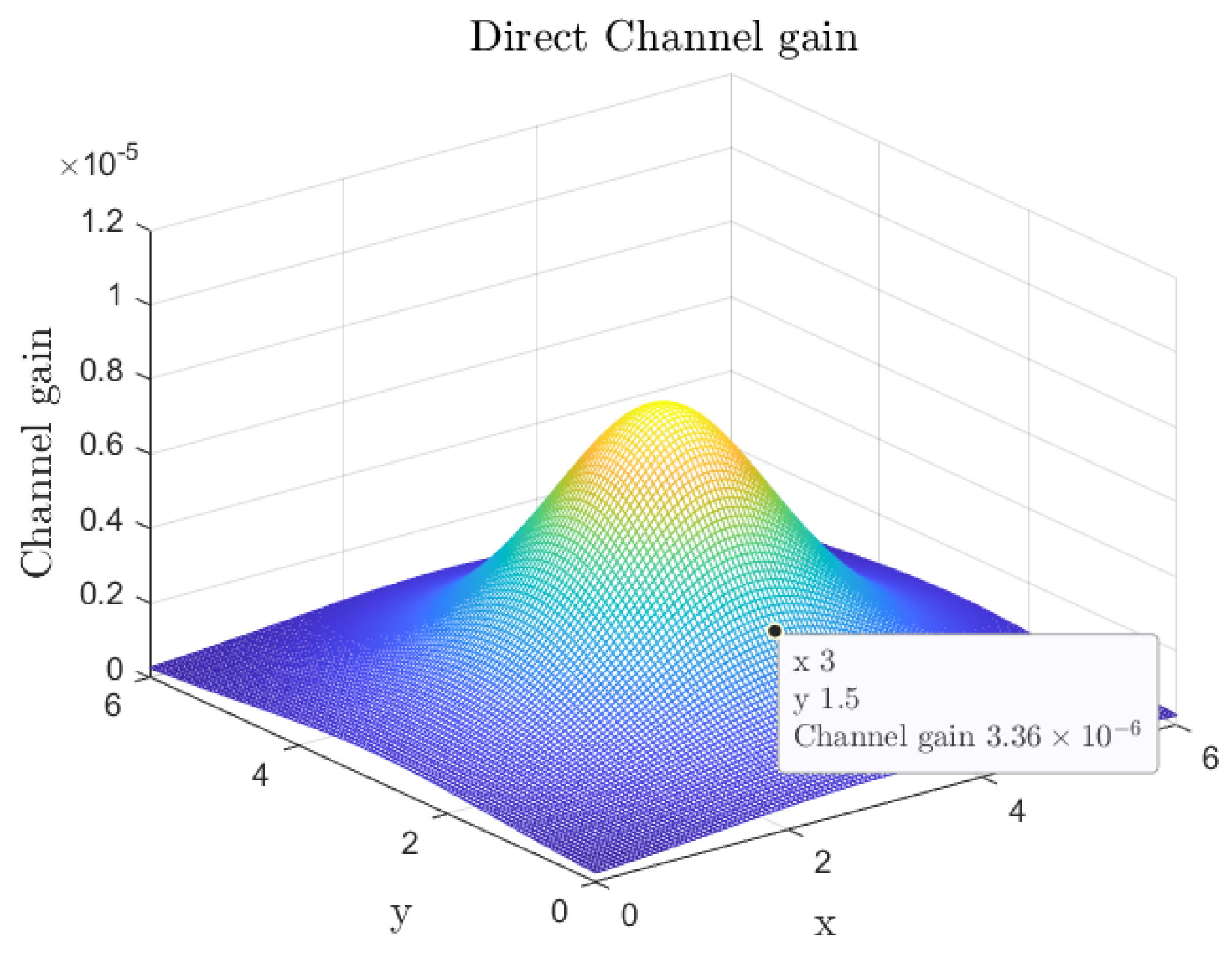
An IRS-aided SISO VLC system with K IRS units is considered in a room of size 6 m × 6 m × 3 m . The coordinate origin is located in one corner of the ceiling in the x o y plane as shown in Figure 1. The LED is located at ( 3 , 3 , 0 ) and the PD at ( 3 , 1.5 , 2 ) . The IRS units of size 0.01 × 0.01 are evenly deployed on the wall in the x o z plane from point ( 2.965 , 0 , 1.215 ) within a rectangle area. The LoS and IRS-reflected NLoS channel gains are calculated according to (2) and (4). The rest of the simulation parameters are listed in Table 1.
The jointly optimized PAM constellation and reflectances are employed in the tunable IRS-aided VLC links. The evenly distributed PAM constellation points with the simple scaling-based dimming scheme are adopted for the mirror-based IRS-aided VLC links with all reflectances set to γ to make the results comparable [15]. Moreover, the gray coding scheme is applied to label the constellation points, and maximum likelihood (ML) detection is used in the demodulation:
s ^ = arg min s m Y ( h L + r m T h N L ) A s m .

4.2. Channel Gain

Figure 2 and Figure 3 show the channel gain distribution for the VLC system without and with IRS units, respectively. The reflectances of the IRS units in Figure 3 are set to be its maximum γ = 0.9 to illustrate the channel gain improvement due to the IRS units. It is observed that the total channel gains increase significantly with the IRS-reflected NLoS channels. Moreover, the exact enhancement of the channel gain relies on both the locations of the LED and the PD and the placement of the IRS units, because of the changing distances and angles, e.g., R k S 2 and θ R k , D M S , within the IRS reflected channel gain Formula (4).

4.3. BER Performance

Figure 4 shows the BER performance with respect to the signal-to-noise ratio (SNR) for different modulation orders when ξ = 0.5 , which demonstrates a significant BER performance improvement introduced by the IRS. Given a fixed PD location with a certain direct channel, the BER performance is improved due to the total channel gain increase shown in Figure 3. Furthermore, the SNR in the received PD depends on many factors in practical VLC systems, such as the transmitter power, the distance of the communication channel (or the locations of the transceivers and the IRS units), the noise power, and the interference of the background light.
In Figure 5, the BER performance of the tunable IRS-aided SISO VLC systems with the optimized constellation and reflectances are compared for different dimming coefficient ξ . The BER performance improvement shows a strong correlation with the dimming coefficient. Specifically, the BER performance of ξ = 0.5 outperforms that of ξ = 0.7 which outperforms that of ξ = 0.3 for 2-PAM. While for 8-PAM and 16-PAM, the BER curves for ξ = 0.5 and ξ = 0.7 are exactly the same and exceed that of ξ = 0.3 . This observation indicates an extra BER performance enhancement for ξ = 0.7 because the BER for ξ = 0.3 is supposed to be the same as that for ξ = 0.7 for VLC systems with no IRS or with mirror-based IRS [18].
To reveal the extra BER performance enhancement for ξ = 0.7 , Figure 6 shows the BER curve of 8-PAM modulation with a varying dimming coefficient employing the tunable IRS and the mirror-based IRS, respectively. For comparison purposes, we assume that the channel gains reflected by the tunable IRS and mirror-based IRS are the same. It is shown that the best BER is achieved at ξ = 0.5 , and the BER incorporating the mirror-based IRS is symmetric about ξ = 0.5 . This is not surprising because dimming usually degrades communication performance and the dimming related capacity has been shown to be symmetrical with respect to ξ = 0.5 [15,18]. But the BER performance for ξ > 0.5 is improved by the tunable IRS and can be enhanced to its best as ξ = 0.5 with the optimized constellations and reflectances, which means the tunable IRS units not only improve the BER performance due to larger channel gains but also relax the dimming constraint. Thus, the BER performance for ξ = 0.7 exceeds that for ξ = 0.3 and may reach ξ = 0.5 when employing sufficient tunable IRS units. The results are consistent with the BER curves in Figure 5.

4.4. Constellations

To reveal the reason of the extra BER performance enhancement for ξ > 0.5 , Figure 7 and Figure 8 show the transmitted and received 4-PAM constellation points for ξ = 0.3 and ξ = 0.7 , respectively. For the sake of a convenient comparison, the peak light intensity A is normalize to 1. In Figure 7, the transmitted and received constellation points incorporating the tunable metasurface-based IRS units are distributed exactly the same with that incorporating the mirror-based IRS units, which means the BER performance is improved only because of the enlarged NLoS channel gain in the case of ξ 0.5 so that a higher received SNR can be achieved. While in Figure 8, the received constellation points of the tunable IRS are distributed with a larger minimum constellation interval compared to that of the mirror-based IRS. And the received constellation points do not satisfy the dimming constraint anymore, which means that the proposed optimal transmit constellation and IRS reflectance can relax the dimming constraint under the condition of ξ 0.5 , thus resulting in the extra BER performance improvement shown in Figure 5 and Figure 6. In addition, the dimming relaxation may lead to overlapping transmitted constellation points, as shown in Figure 8.

5. Conclusions

In this paper, a joint PAM constellation and IRS reflectance optimization problem was formulated to improve the BER performance by maximizing the minimum distance between received constellation points under the dimming constraint. The problem was divided into a convex receive constellation optimization problem and a feasible transmit constellation and IRS reflectance problem; the latter can be further decomposed and relaxed into two constrained least square problems that can be solved alternatively. The simulation results showed the performance improvement benefits from the additional IRS-reflected NLoS gain and the dimming constraint relaxation when the dimming coefficient is greater than 0.5.

Author Contributions

Conceptualization, L.J.; data curation, Q.W.; formal analysis, L.J.; funding acquisition, L.J.; methodology, L.J.; project administration, Y.Z.; resources, Y.Z.; software, L.J. and Q.W.; supervision, L.J.; validation, Y.Z.; visualization, Q.W.; writing—original draft, L.J.; writing—review & editing, L.J. and Y.Z. All authors have read and agreed to the published version of the manuscript.

Funding

This work was funded in part by the National Natural Science Foundation of China under grant 62301257, and in part by the Natural Science Foundation of Jiangsu Province under grant BK20200488.

Institutional Review Board Statement

Not applicable.

Data Availability Statement

The data presented in this study are available upon request from the corresponding author.

Conflicts of Interest

The authors declare no conflicts of interest. The funders had no role in the design of the study; in the collection, analyses, or interpretation of data; in the writing of the manuscript; or in the decision to publish the results.

Abbreviations

The following abbreviations are used in this manuscript:
VLCVisible light communication;
IRSIntelligent reflecting surface;
LoSLine of sight;
NLoSNon-light of sight;
SISOSingle-input single-output;
BERBit error rate;
6GSixth-generation;
LEDLight-emitting diode;
RFRadio frequency;
MIMOMultiple-input multiple-output;
DPCDirty-paper coding;
IM/DDIntensity modulation and direct detection;
PAMPulse amplitude modulation;
CCUCentral control unit;
PDPhoto-detector;
DCDirect channel;
FoVField of view;
LDLaser diode;
OOKOn–Off keying;
PPMPulse position modulation;
SERSymbol error rate;
MLMaximum likelihood;
SNRSignal-to-noise ratio.

Appendix A

Since 0 s m 1 and 0 r m , k γ , we have
s m = ( h L + r m T h N L ) s m
0 s m ( h L + γ 1 M T h N L )
Therefore, (14) is proved.
If the reflectance of all IRSs is equal to 0, 1 M 1 M T s = h L ξ , which is the lower bound for 1 M 1 M T s . In addition, we have
1 M 1 M T s = 1 M m = 1 M s m
= 1 M m = 1 M ( h L + r m T h N L ) s m
= h L ξ + 1 M m = 1 M r m T h N L s m
h L ξ + 1 M m = 1 M γ 1 M T h N L s m
= h L ξ + γ 1 M T h N L ξ
Therefore, (13) is proved.

References

  1. Sun, S.; Yang, F.; Song, J.; Han, Z. Joint Resource Management for Intelligent Reflecting Surface–Aided Visible Light Communications. IEEE Trans. Wirel. Commun. 2022, 21, 6508–6522. [Google Scholar] [CrossRef]
  2. Sun, S.; Wang, T.; Yang, F.; Song, J.; Han, Z. Intelligent Reflecting Surface-Aided Visible Light Communications: Potentials and Challenges. IEEE Veh. Technol. Mag. 2022, 17, 47–56. [Google Scholar] [CrossRef]
  3. Abumarshoud, H.; Mohjazi, L.; Dobre, O.A.; Di Renzo, M.; Imran, M.A.; Haas, H. LiFi through Reconfigurable Intelligent Surfaces: A New Frontier for 6G? IEEE Veh. Technol. Mag. 2022, 17, 37–46. [Google Scholar] [CrossRef]
  4. Pan, C.; Zhou, G.; Zhi, K.; Hong, S.; Wu, T.; Pan, Y.; Ren, H.; Renzo, M.D.; Lee Swindlehurst, A.; Zhang, R.; et al. An Overview of Signal Processing Techniques for RIS/IRS-Aided Wireless Systems. IEEE J. Sel. Top. Signal Process. 2022, 16, 883–917. [Google Scholar] [CrossRef]
  5. Wu, Q.; Zhang, R. Towards Smart and Reconfigurable Environment: Intelligent Reflecting Surface Aided Wireless Network. IEEE Commun. Mag. 2020, 58, 106–112. [Google Scholar] [CrossRef]
  6. Liu, H.; Yuan, X.; Zhang, Y.J.A. Matrix-Calibration-Based Cascaded Channel Estimation for Reconfigurable Intelligent Surface Assisted Multiuser MIMO. IEEE J. Sel. Areas Commun. 2020, 38, 2621–2636. [Google Scholar] [CrossRef]
  7. Elmossallamy, M.A.; Sultan, R.; Seddik, K.G.; Li, G.Y.; Han, Z. Maximizing dirty-paper coding rate of RIS-assisted multi-user MIMO broadcast channels. Intell. Converg. Netw. 2022, 3, 64–73. [Google Scholar] [CrossRef]
  8. Abdelhady, A.M.; Salem, A.K.S.; Amin, O.; Shihada, B.; Alouini, M.S. Visible Light Communications via Intelligent Reflecting Surfaces: Metasurfaces vs Mirror Arrays. IEEE Open J. Commun. Soc. 2021, 2, 1–20. [Google Scholar] [CrossRef]
  9. Sun, S.; Yang, F.; Song, J.; Zhang, R. Intelligent Reflecting Surface for MIMO VLC: Joint Design of Surface Configuration and Transceiver Signal Processing. IEEE Trans. Wirel. Commun. 2023, 22, 5785–5799. [Google Scholar] [CrossRef]
  10. Sun, S.; Yang, F.; Song, J. Sum Rate Maximization for Intelligent Reflecting Surface-Aided Visible Light Communications. IEEE Commun. Lett. 2021, 25, 3619–3623. [Google Scholar] [CrossRef]
  11. Aboagye, S.; Ngatched, T.M.N.; Dobre, O.A.; Ndjiongue, A.R. Intelligent Reflecting Surface-Aided Indoor Visible Light Communication Systems. IEEE Commun. Lett. 2021, 25, 3913–3917. [Google Scholar] [CrossRef]
  12. Zhi, K.; Pan, C.; Ren, H.; Chai, K.K.; Elkashlan, M. Active RIS Versus Passive RIS: Which is Superior with the Same Power Budget? IEEE Commun. Lett. 2022, 26, 1150–1154. [Google Scholar] [CrossRef]
  13. Bhowmik, T.; Chowdhary, A.K.; Sikdar, D. Polarization- and Angle-Insensitive Tunable Metasurface for Electro-Optic Modulation. IEEE Photonics Technol. Lett. 2023, 35, 879–882. [Google Scholar] [CrossRef]
  14. Lee, K.; Park, H. Modulations for Visible Light Communications with Dimming Control. IEEE Photonics Technol. Lett. 2011, 23, 1136–1138. [Google Scholar] [CrossRef]
  15. Wang, T.; Yang, F.; Song, J.; Han, Z. Dimming Techniques of Visible Light Communications for Human-Centric Illumination Networks: State-of-the-Art, Challenges, and Trends. IEEE Wirel. Commun. 2020, 27, 88–95. [Google Scholar] [CrossRef]
  16. Drost, R.J.; Sadler, B.M. Constellation Design for Channel Precompensation in Multi-Wavelength Visible Light Communications. IEEE Trans. Commun. 2014, 62, 1995–2005. [Google Scholar] [CrossRef]
  17. Boyd, S.; Vandenberghe, L. Convex Optimization; Cambridge University Press: New York, NY, USA, 2004. [Google Scholar]
  18. Jia, L.; Shu, F.; Huang, N.; Chen, M.; Wang, J. Capacity and Optimum Signal Constellations for VLC Systems. J. Light. Technol. 2020, 38, 2180–2189. [Google Scholar] [CrossRef]
Figure 1. A tunable IRS-aided SISO VLC System.
Photonics 11 00840 g001
Figure 2. The channel gain distribution for point-to-point VLC systems.
Photonics 11 00840 g002
Figure 3. Channel gain distribution for IRS-aided VLC system.
Photonics 11 00840 g003
Figure 4. Comparison of the BER performance with and without the IRS for ξ = 0.5 .
Photonics 11 00840 g004
Figure 5. BER performance with the optimized constellation and reflectances for ξ = 0.3 , 0.5 , and 0.7 .
Photonics 11 00840 g005
Figure 6. BER performance versus varying ξ for 8PAM.
Photonics 11 00840 g006
Figure 7. The 4-PAM constellations for 16 IRS-aided VLC systems when ξ = 0.3 .
Photonics 11 00840 g007
Figure 8. The 4-PAM constellations for 16 IRS-aided VLC systems when ξ = 0.7 .
Photonics 11 00840 g008
Table 1. Simulation parameters.
ParameterValue
The number of IRS units K16, 32
The modulation order M2, 4, 8, 16
The dimming coefficient ξ 0.1∼0.9
The Lambertian index m1
The PD area A P 1 cm 2
The FoV of the concentrator Ψ c 70
The optical filter gain g ( ψ ) 1
The refractive index n 1.5
β 100
The maximum reflectance γ 0.9
Disclaimer/Publisher’s Note: The statements, opinions and data contained in all publications are solely those of the individual author(s) and contributor(s) and not of MDPI and/or the editor(s). MDPI and/or the editor(s) disclaim responsibility for any injury to people or property resulting from any ideas, methods, instructions or products referred to in the content.

