Abstract
This paper proposes an asymmetric scanning holography cryptosystem based on the Elgamal algorithm. The method encodes images with sine and cosine holograms. Subsequently, each hologram is divided into a signed bit matrix and an unsigned hologram matrix, both encrypted using the sender’s private key and the receiver’s public key. The resulting ciphertext matrices are then transmitted to the receiver. Upon receipt, the receiver decrypts the ciphertext matrices using their private key and the sender’s public key. We employ an asymmetric single-image encryption method for key management and dispatch for securing imaging and transmission. Furthermore, we conducted a sensitivity analysis of the encryption system. The image encryption metrics, including histograms of holograms, adjacent pixel correlation, image correlation, the peak signal-to-noise ratio, and the structural similarity index, were also examined. The results demonstrate the security and stability of the proposed method.
1. Introduction
Information security is important and ubiquitous. Specifically, optical imaging encryption technology is an integral part of information security [1,2]. The history of optical imaging encryption dates back to Refregier and Javidi, who built the first optical encryption system [3]. An optical encryption system first produces an image with a first random phase mask in the input plane. The Fourier transform of the product is subsequently encoded by a second random phase mask. This idea is known as double-random phase encoding (DRPE). Additional studies have been conducted using the same methodology [4,5,6,7,8]. However, most of these methods are vulnerable to security attacks, including chosen-ciphertext attacks (CCAs), known-plaintext attacks (KPAs), and ciphertext-only attacks (COAs). To augment security, research has investigated the management of security keys and the nonlinear configurations of optical systems. Examples of the efforts include the combination of DRPE with other methods, such as fractional Fourier transform, linear canonical transform, Hartley transform, gyrator transform, Fresnel transform, quantum technology, ghost imaging, photon computing, and laser detection [9,10,11,12,13,14,15]. Most of these methods, however, encrypt and decrypt in one- or two-dimensional phase or amplitude using a pure optical technology.
To exploit higher-dimensional information encryption, holographic technology has been used to encode more complex objects and multidimensional images. The idea of holography was first proposed by Dennis Gabor in 1948 [16]. Holography comprises two main categories: optical and digital holography. Digital holography is a combination of digital processing technology and an optical system that usually uses charge-coupled detectors (CCDs) instead of traditional holographic recording materials to record holograms. Digital holography is highly reliant on computers to collect, process, and analyze the collected holograms for digital reconstruction of the objects of interest, thus performing 3D information processing.
Optical scanning holography (OSH) is a type of digital holography. It is based on the concept of scanning a 3D object using 2D optical scanning to obtain 3D information of the object. Poon demonstrated the usefulness of this technology and named the technology OSH [17]. OSH finds diverse applications, one of which is optical cryptography. Optical encryption has excellent features, such as high-speed parallel processing, large key space, high security levels, and the capability to encode the spatial and frequency contents of images simultaneously. Recently, Lee et al. [18] enhanced OSH technology by developing a rapid and automated method for holographic image reconstruction. In the face of the emerging and increasingly mature technology of holography, other studies on holographic encryption techniques have been conducted; for instance, heterogeneous image encryption algorithms, integration of Arnold transform and chaos mapping image encryption methods, and techniques using neural networks to compress and encrypt holograms have also been used [19].
Previous research has demonstrated that when optical encryption is symmetrical, i.e., the same key is used in encryption and decryption, it is vulnerable to different attacks, such as KPAs, CCAs, and COAs. In addition, the overheads of key management and distribution are considerable. Some researchers have used a combination of optical and digital encryption technologies attempting to address vulnerability. Various digital encryption technologies have also been proposed, such as the symmetric cryptographic algorithms DES, 3DES, Blowfish, IDEA, TEA, CAST, Rijndael, RC6, Serpent, Twofish, MARS, and AES, which differ only in key length, security level, and encryption speed [20,21,22]. However, the management of symmetric keys is difficult for the users, and the cost of storing the keys increases with the expansion of key length. Compared with symmetric encryption, asymmetric encryption algorithms, such as RSA, ECC, and Elgamal, do not involve key delivery and thus are more suitable for practical applications [23,24]. Tsang et al. proposed the encryption of an image by combining the asymmetric algorithm RSA and optical scanning holography [19]. But the keys of RSA already exceeded 1024 bits, leading to an increase in computational time. Elgamal offers superior reliability and security compared to RSA, making it advantageous for generating different ciphertexts from the same plaintext. This characteristic further inspired the study [25,26,27,28].
We use two variations of the Elgamal algorithm to encrypt optical scanned holograms. Notably, Elgamal encryption and decryption require fewer key bits than RSA, resulting in fewer key agreements and higher security. The method is less computationally extensive than that of the RSA method and thus affordable in computing for practical real-world applications. The captured optical scanned holograms are complex-valued, comprising a real component and an imaginary component, which are referred to as the “cosine” and the “sine” holograms, respectively. The value of each hologram pixel is represented by a decimal number. Similar to encryption methods in general, the Elgamal algorithm is only applicable to integers, not decimal values. In this paper, we resolve the encryption challenge of decimals through Elgamal encryption and expand the application scope by converting decimals into fractions. These fractions are then utilized in the encryption process. Our research demonstrates a new scheme for high-security asymmetric image encryption, which can find rich engineering applications, such as space optical communication, remote sensing, and three-dimensional information encryption. The proposed method could also be applied to other wavelengths, including the infrared band.
The organization of this paper is given as follows. In Section 2, the principles of optical scanning holography and its applications in acquiring and encrypting holograms of physical objects are described. In Section 3, we outline two different Elgamal encryption methods, a simplified and a three-round handshake version, both of which will be adopted in our encryption scheme. Encrypting OSH holographic data with the two Elgamal encryption methods is presented in Section 4. Experimental results and a security analysis of the proposed encryption system are described in Section 4 and Section 5, respectively, followed by a conclusion summarizing the key findings.
2. Optical Scanning Holography: Digital Hologram Acquisition and Encryption
Poon and Korpel [17] pioneered the single-pixel optical scanning holographic technique. In contrast to the typical CCD camera-based digital holographic technique, the significant advantage of the technique is that the resolution of the imaging is not limited by the resolution of the CCD sensor. The optical scanning holographic setup is shown in Figure 1.
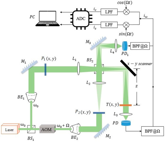
Figure 1.
Diagram of optical scanning holographic system. : beam splitter; : acousto-optic modulator; silver mirrors; Fourier lenses; for collecting light energy; and PD1: photo-detectors; : low-pass filter; : analog-to-digital converter; : digital computer.
The system consists of two pupils ( and ) and two beam splitters ( and ). A laser beam with temporal frequency is separated into two beams through , and the laser frequency is changed from to by an acousto-optic modulator (AOM). The two beams are collimated using beam expanders and The two pupils are located at the front focal planes of lenses and . The beam splitter is used to combine the two optical beams from the two arms of the interferometer, and the combined beam is projected onto the object through the x–y scanner for a raster scan. is the object’s intensity distribution to be scanned, which is located at a distance from the back focal plane of lens . Lenses and collect the light energy onto the photo-detectors (PD and PD1). The two beams with frequency and through pupils and at the focal planes of lenses and are
where denotes the Fourier transform, is the Fourier transform of , is the imaginary unit, is the wave number of the laser, and is the focal length of lenses and . After propagating a distance z toward , they are expressed as
where denotes the two-dimensional convolution involving coordinates and y and is the spatial impulse response in Fourier optics [29], and the combined scanning field on the object slide is
After raster scanning T by , the photo-detector PD generates a heterodyne current passing through the lock-in amplifier to give two outputs: and , namely, the in-phase hologram (cosine hologram) and the quadrature hologram (sine hologram), after digital storage in the PC. It has been shown that a complex hologram can be constructed and given by [17]
where denotes the inverse Fourier transform. is expressed in terms of the two pupil functions as
where and are the spatial frequencies along the x and y directions and denotes the complex conjugate of . As reflected in Equations (1)–(7), the sine and the cosine holograms can be optically encrypted using the two pupils and , which serve as the encryption and the decryption keys.
To decrypt the image, we need to find out the complex conjugate of or simply select the appropriate and in the decryption stage. In the decryption stage, we have, using Equation (6),
when , which means that and the decryption of the object can be obtained.
3. Elgamal Encryption Algorithm
In Section 2, we described the principles of OSH and how optical encryption can be embedded into a system. It can be inferred from Equations (7) and (8) that encryption and decryption of the holographic data rely on the pair of pupil functions and , which serve as the encryption as well as the decryption keys. A key is either provided by the sender or the receiver via the communication channel. This kind of cryptography is commonly referred to as symmetrical encryption. If the encryption key is intercepted by a man in the middle (MITM) while being sent from the transmission end to the receiving end, or vice versa, then all holographic data that are encrypted with the key can be easily recovered. In view of this, we assign a delta function to both pupil functions and do not incorporate the optical encryption in the hologram acquisition process.
Instead of employing the pupil functions for encryption, which only provides a low level of data protection, a more secure approach is through asymmetrical encryption, whereby the encryption key that is exchanged between the two parties (if any) is different from the decryption key that is privately kept by the receiver. In this way, even if the encryption key is exposed, it cannot be used to decrypt the encoded data. In this paper, we propose to adopt two types of asymmetrical encryption to enhance the protection of holographic data. The first one is a simplified version of the classical Elgamal method, while the second one is a three-round handshake Elgamal encryption scheme. Although RSA is another well-known asymmetric encryption algorithm, it is time-consuming. The computation loading of RSA encryption is intensive, and the process can be rather lengthy in encrypting large datasets [19]. Compared with RSA, the improved Elgamal encryption scheme is more secure and effective.
3.1. Simplified Elgamal Encryption
The Elgamal encryption algorithm is an asymmetric encryption algorithm proposed by Taher Elgamal in 1985 [26]. There are different variations on the method, and we have adopted a simplified version as part of our encryption scheme. Referring to Figure 2 showing the communication between a receiver, Bob, and a sender, Alice, Bob requests Alice to encrypt the number M with the Elgamal algorithm and send him the ciphertext. The encryption and decryption processes can be divided into three stages and outlined as follows. To begin with, let denote the modulo operation, with being the remainder of .
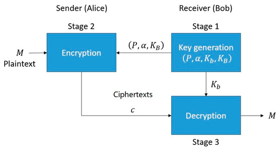
Figure 2.
A simplified Elgamal encryption algorithm as part of our proposed method.
Stage 1: Key Generation Algorithm.
At the receiving end, Bob first establishes his public and private keys.
(1) Randomly select a large prime number . Here, we can use the Fermat prime test or the Miller–Rabin prime test to determine whether the randomly generated number is prime. A cyclic group G of large prime order with a generator is generated.
(2) Randomly choose an integer as the private key and compute the public key as
The set of public key parameters , is sent to the sender for encrypting the plaintext.
Stage 2: Encryption Algorithm.
At the sending side, Alice receives the public key parameters from Bob and uses them to encrypt a plaintext M which is in the form of a positive integer, as given by
Stage 3: Decryption Algorithm.
The ciphertext is sent to Bob and decrypted using Bob’s private key , and the original text is obtained after decryption as
It can be inferred from Equations (10) and (11) that Elgamal encryption is vulnerable to chosen-plaintext attack. If the plaintext M and the ciphertext are known, a set of plausible private keys that satisfies Equation (10) can be deduced with the brute force method. With more pairs of plaintexts and their ciphertexts, the plausible private keys can be narrowed down to a few possibilities or unambiguously identified. The cracked key(s) can be used to decrypt future encrypted messages. Having said that, deducing a private key with brute force is a difficult task. First, the attacker has to know the correspondence between the plaintext and its ciphertext. Second, the process is computationally intensive for large values of P.
Nevertheless, to prevent the chosen-plaintext attack, we also incorporated a three-round handshake Elgamal encryption method which cannot be compromised by plaintext attack.
3.2. Three-Round Handshake Elgamal Encryption Algorithm
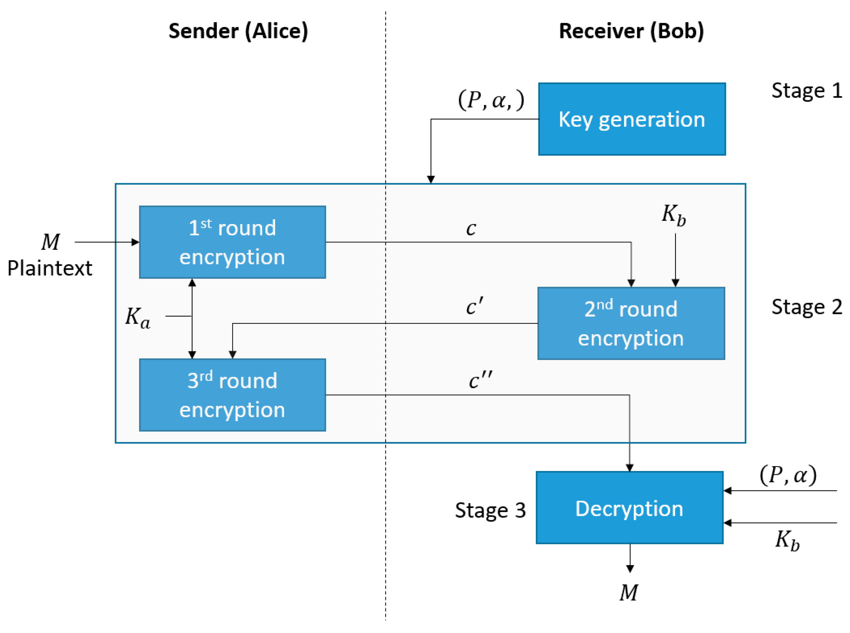
Referring back to the communication between the receiver, Bob, and the sender, Alice, where Bob requests Alice to encrypt a number M with the Elgamal algorithm and send him the ciphertexts [26], different from the simplified Elgamal algorithm depicted in Figure 2 that involves the distribution of a public key, we adopted an enhanced version comprising a three-round handshake operation. The encryption and decryption processes can be divided into three stages outlined in Figure 3, including key generation, three-round handshake encryption, and decryption. The following terminology is adopted. Let denote the modulo operation, with x being the remainder of , and let denote the inverse modulo operation, where .
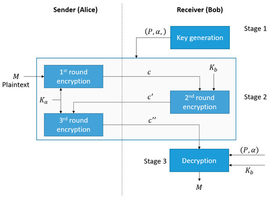
Figure 3.
Our proposed three-round handshake Elgamal encryption algorithm.
Stage 1: Generating shared parameters for both parties.
At the receiving end, Bob randomly selects a large prime number and generator . The prime number P and the generator are sent to Alice. Both parties will use these two parameters in encryption and/or decryption.
Stage 2: Three-Round Handshake Encryption Algorithm.
At the sending side, Alice encrypts a plaintext M which is in the form of a positive integer. The process comprises three rounds of encryption, whereby the outcome of each process is exchanged between the two parties via a sequential handshaking arrangement. The entire operation can be divided into three steps, as shown below.
Step 1: Alice randomly selects an integer as her private key. The ciphertext is computed and sent to Bob as given by
where .
Step 2: Upon receiving the ciphertext from Alice, Bob calculates the ciphertext and sends it to Alice, with
where .
Step 3: Alice receives the ciphertext and uses to calculate then sends it to Bob.
Stage 3: Decryption Algorithm.
Bob receives the ciphertext and decrypts it using Bob’s private key , and the original text is obtained after decryption given by
From Equations (12)–(14), it is evident that the sender’s and the receiver’s private keys ( and ) can be randomly changed to generate different ciphertexts (, , and ) for the same plaintext. The encrypted message can only be decrypted with the private key of Bob, as given in Equation (15). This prevents known or chosen-plaintext attacks, whereby known pairs of plaintexts and ciphertexts are used as look-up tables to decrypt ciphertexts in the future.
As an example, suppose P = 113, = 2, = 50, and . The plaintext M is an integer having the value 100.
First, from the private keys of Alice and Bob, we compute the corresponding parameters and as
Next, the ciphertexts that are exchanged between Bob and Alice are given by
The receiver decrypts with Equation (15), recovering the plaintext as
4. Proposed Optical Scanning Holographic System with Elgamal Encryption
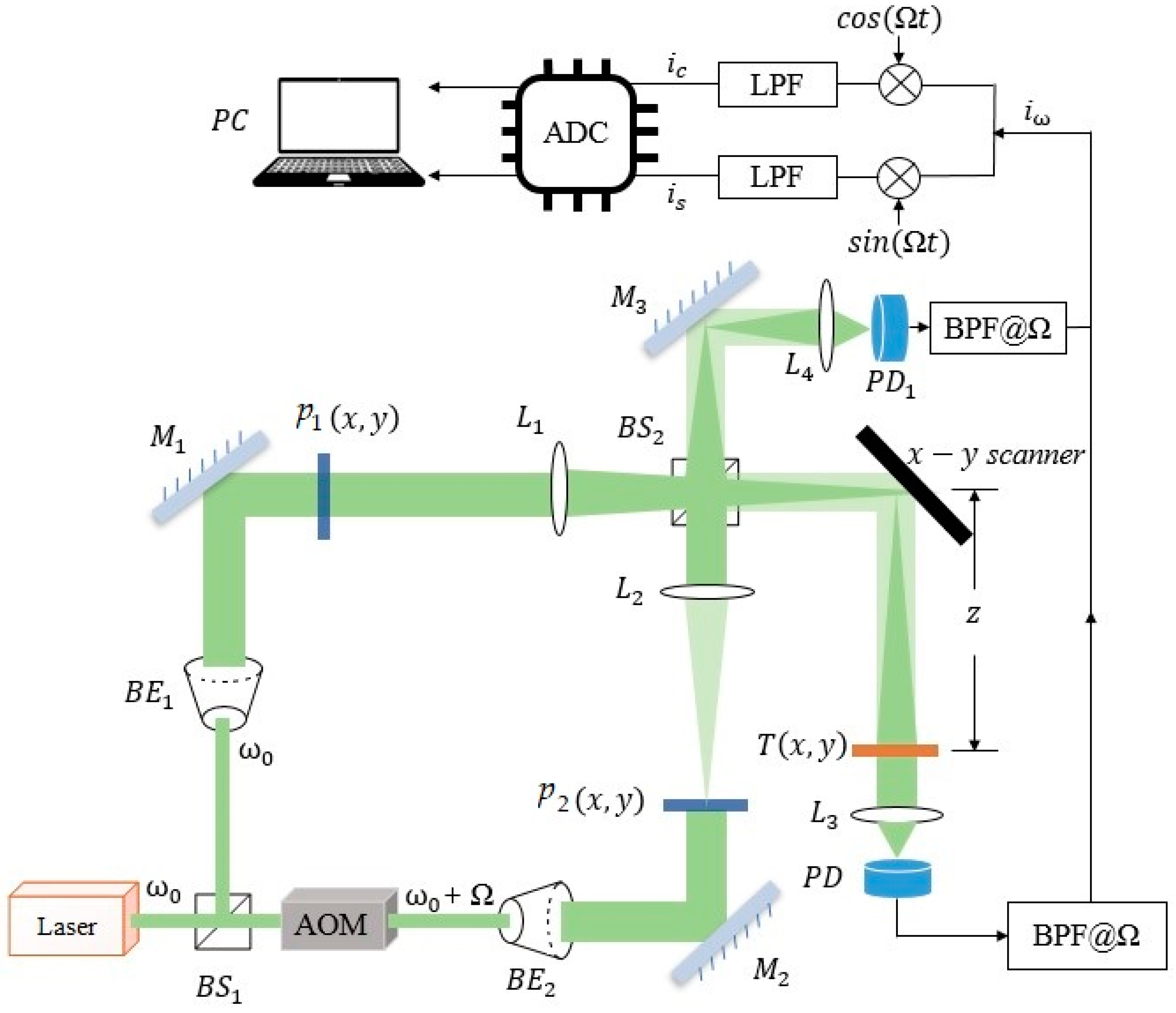
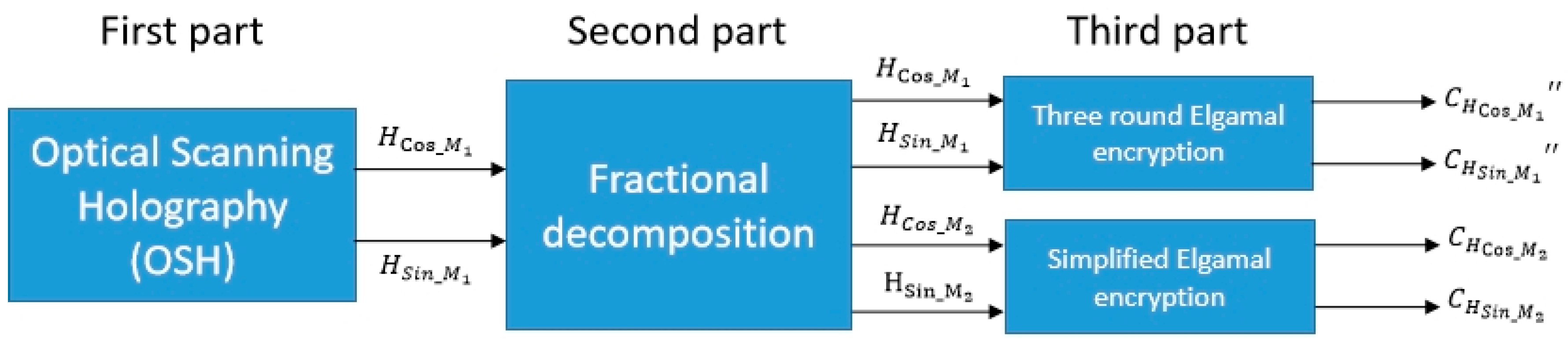
The proposed OSH system is composed of two parts, as shown in Figure 4. The first part is the classical OSH, which has been described in Section 2. As mentioned previously, the pupil functions and are set to be a delta function, which does not lead to optical encryption. The second part is a process referred to as fractional decomposition, converting the cosine hologram into two arrays, , and the sine hologram into arrays and . All four decomposed arrays (, , and ) are identical in size to the cosine and the sine hologram. The final part is our proposed Elgamal encryption scheme, described in Section 3. The simplified Elgamal encryption is applied to and , while the three-round encryption algorithm is applied to and . Details of the fractional decomposition and the encryption process are described as follows.
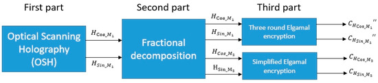
Figure 4.
Our proposed OSH system with Elgamal encryption.
4.1. Fractional Decomposition
The captured optical scanning hologram comprises the real hologram and the imaginary hologram , which are real numbers. Thus, each pixel in the holograms has to be converted into an integer representation prior to encryption with the Elgamal algorithm. In our approach, a real number is converted into an ordered pair of integers , which is referred to as the fractional decomposed pair. The process can be summarized into three steps and described as follows. To begin with, consider a real number a representing the value of an arbitrary pixel in either a cosine or a sine hologram.
Step 1:
The number a is converted into a fractional representation comprising a numerator and a denominator, both being an integer.
where .
Step 2:
To obtain the first member of the fractional decomposed pair, the exclusive or (XOR) operation is conducted on the absolute values of the numerator and denominator. Denoting the XOR operation as and the absolute value of as , we have
Step 3:
First, the sign bit s of the real number is determined as
The second element of the ordered pair is obtained by replacing the least significant bit (LSB) of the denominator with the sign bit of a, as given by
where denotes the LSB replacement operator.
Without loss of generality, we assume that the dynamic range of the hologram pixel is bounded within the range . As an example, let , which can be converted into the fraction . The sign bit 1 as is positive.
The numerator and the denominator can be expressed in binary form as given by
Applying Equations (17) and (19) to and , we obtain
Hence, the fractional decomposed pair is or in base-10 representation.
4.2. Recovering Values from Fractional Decomposed Pairs
From the fractional decomposed pair obtained with Equations (17) and (19), the original decimal value can be recovered as follows.
The absolute value of the numerator can be found by performing an exclusive or operation on and , i.e.,
By comparison with Equations (17) and (19), it can be seen that the LSB of the numerator may not retain its original value, as is derived from replacing the LSB of by the sign bits. However, the change is negligible, as the numerator and the denominator are usually represented with 16 bits or more. The original decimal value is obtained as
where if the LSB of is 0 and 1 otherwise.
Referring to the previous example in Section 4.2, we have
It can be seen that the original value of a cannot be fully recovered, but the error is negligible.
4.3. Elgamal Encryption and Decryption of Holographic Data
4.3.1. Encrypting the Holographic Data
Referring to Figure 4, fractional decomposition, based on Equations (16)–(19), is applied to each pixel of the cosine hologram to give a fractional decomposed pair. The first and the second elements of the fractional decomposed pairs are grouped into arrays, , respectively. In the same way, the sine hologram is fractionally decomposed into arrays and .
Each element in is encrypted with the three-round Elgamal encryption algorithm, based on Equations (12)–(14). The result is an encrypted array: . Likewise, is encrypted in the same way to give an encrypted array: .
The elements corresponding to and are encrypted with the simplified Elgamal algorithm based on Equation (10), resulting in a pair of encoded arrays: and .
The four encrypted arrays: , , , and are the ciphertexts of the cosine and the sine holograms, which are sent to the receiver.
4.3.2. Decrypting the Holographic Ciphertexts
Equation (11) is applied to each element in the arrays and to reconstruct the arrays and . Subsequently, Equation (15) is applied to decrypt and into and . Subsequently, Equations (20) and (21) are applied to compute the numerator and the denominator of each pixel of the cosine and the sine holograms. The value of each hologram pixel is computed by dividing the numerator by the denominator of the corresponding pixel.
5. Experimental Results
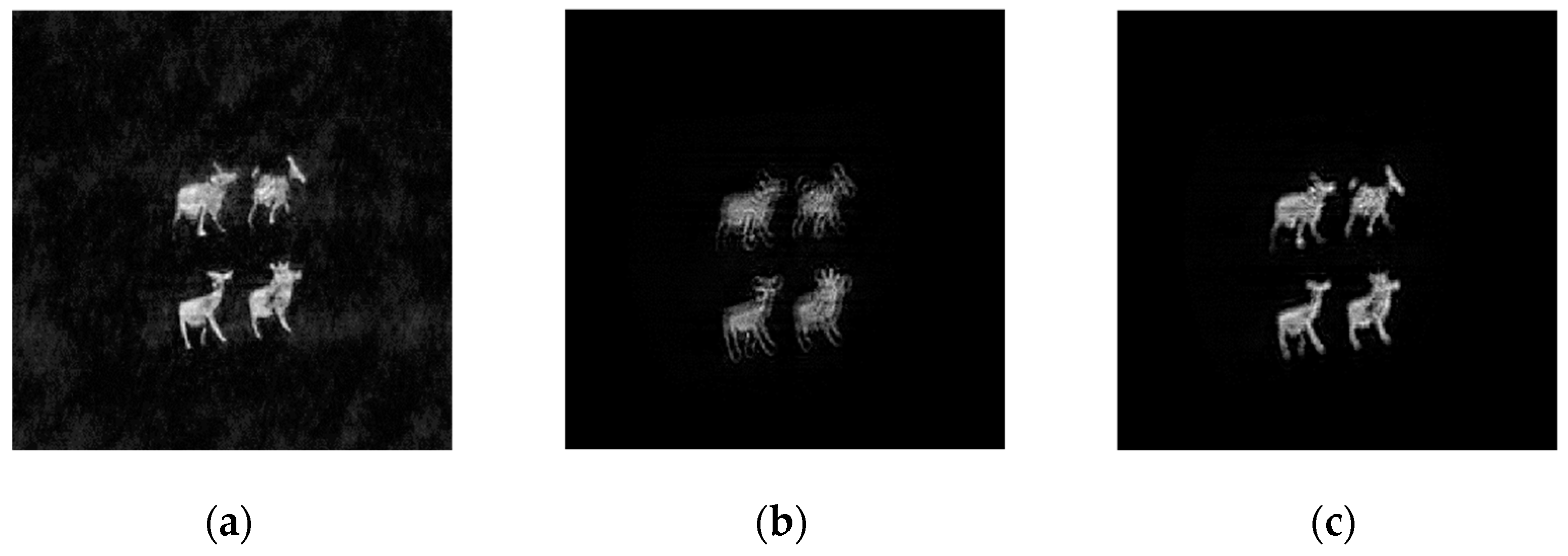
We demonstrate the feasibility and effectiveness of the proposed scheme with experimental results. The optical scanned hologram of an object can be obtained from the OSH system shown in Figure 1. The coherent light source was a 12 mW He–Ne laser with . The heterodyne frequency Ω was set to 25 KHz, = 300 mm, the coding distance = 30 cm, and the two pupil functions and . The original image was composed of four sheep sub-images, as shown in Figure 5a. The physical size of the original image was around 15 mm × 18 mm. It was encoded into the cosine hologram and the sine hologram using the OSH system, as shown in Figure 5b,c. The Elgamal encryption parameter was , . The sender (Alice) chose the random number and computed her own private key The receiver (Bob) chose a random number and computed his public key and sent to Alice.
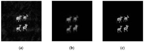
Figure 5.
(a) Four-sheep original image. (b) Cosine hologram. (c) Sine hologram.
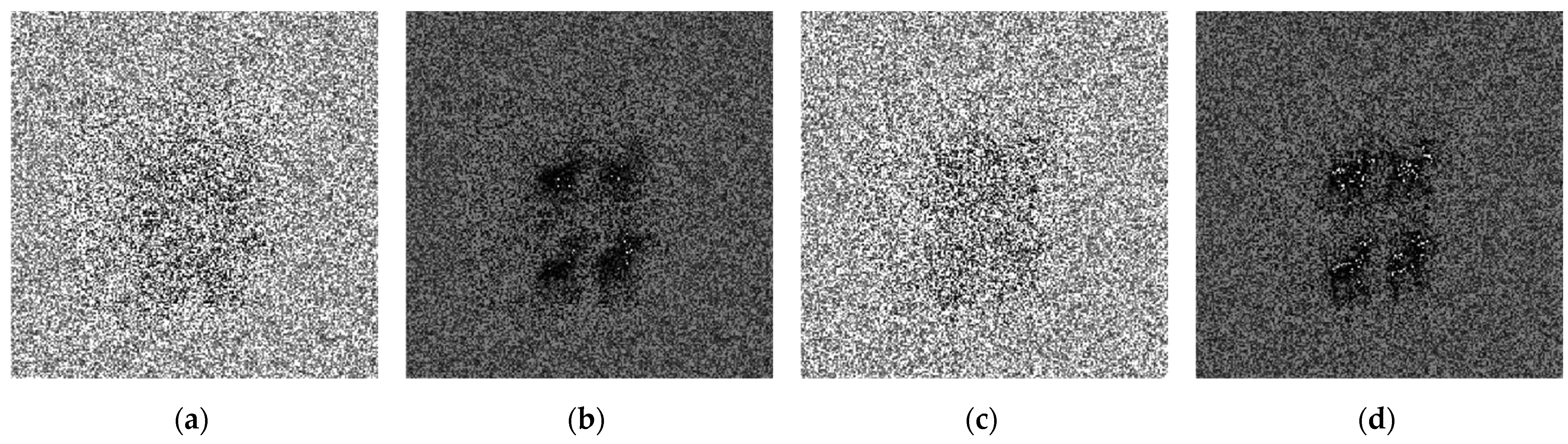
We used MATLAB R2020a on a personal computer to verify the feasibility of the proposed asymmetric system. and performed sign bit extraction and fractional conversion. Next, was performed, leading to and , ). Alice used to encrypt and to encrypt Through three-round transmission and encryption with Bob, finally, he received the ciphertexts and , as shown in Figure 6a–d. Bob used to decrypt and Then, the and holograms were recovered, as shown in Figure 7a,b. Figure 7c shows the decrypted image from the complex hologram H, as described in Section 4.3.2. It can be seen that the plaintext information was well encrypted.

Figure 6.
(a) Cosine sign ciphertext. (b) Unsigned cosine fractional XOR ciphertext. (c) Sine sign ciphertext. (d) Unsigned sine fractional XOR ciphertext.
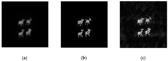
Figure 7.
The reconstructed (a) cosine hologram and (b) sine hologram. (c) The decrypted image.
6. Security Analysis and Discussion
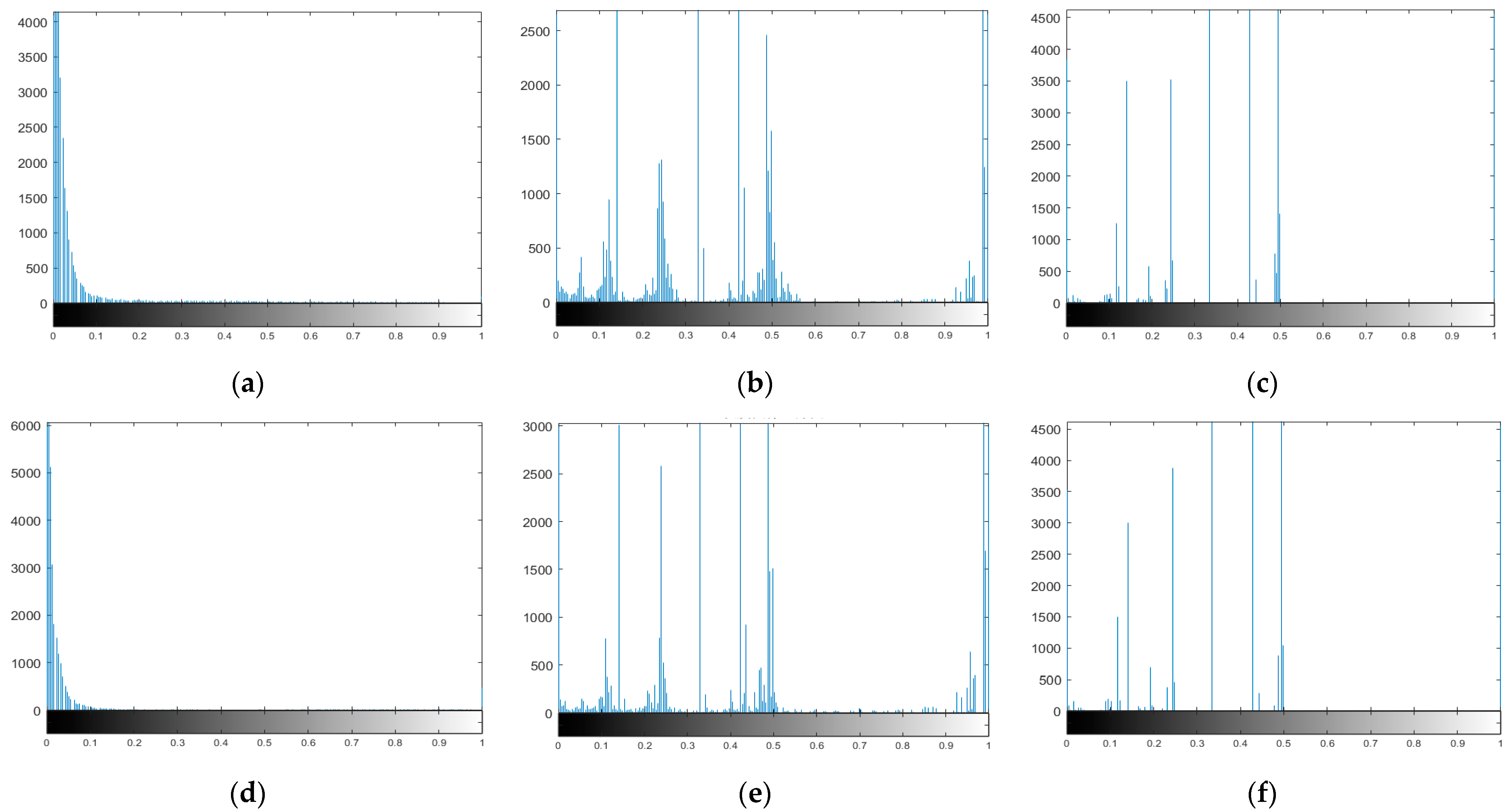
It is important to analyze the security of the encryption system. We calculated the histogram of the hologram because it shows the pixel intensity distribution of the entire hologram. The distribution of the histogram is crucial for security, where a more evenly distributed hologram image can improve security. Histograms of the hologram and its corresponding ciphertext obtained using the Elgamal algorithm are shown in Figure 8. Figure 8a–c are the histograms of the cosine hologram, the unsigned cosine fractional XOR ciphertext, and the cosine sign ciphertext, respectively. Figure 8d–f are the histograms of the sine hologram, the unsigned sine fractional XOR ciphertext, and the sine sign ciphertext, respectively. The pixel distribution of the ciphertexts shown in Figure 8b,c,e,f is more dispersed and uniform than that of the cosine hologram and sine hologram shown in Figure 8a,d. The pixel value of the cosine hologram and the sine hologram is less than 0.2. Therefore, illegal attackers cannot obtain useful information from the ciphertext.
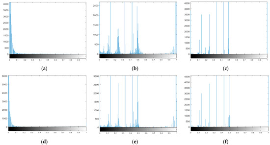
Figure 8.
Histograms of the (a) cosine hologram, (b) unsigned cosine fractional XOR ciphertext, (c) cosine sign ciphertext, (d) sine hologram, (e) unsigned sine fractional XOR ciphertext, and (f) sine sign ciphertext.
To quantitatively analyze the ciphertext and the decrypted images, the mean-square error (MSE) and the peak signal-to-noise ratio (PSNR) were adopted. The MSE and PSNR can be calculated using the following equations:
where and represent the length and width of the image, where X(i, j) is the pixel value of the original image at position (i, j) and Y(i, j) denotes either a ciphertext or a decrypted image. The MSE values between the original image (Figure 5a) and the ciphertext images (Figure 6a,c) were 7531.42 and 6952.31, respectively. The higher the MSE value, the greater the difference between the original and the ciphertext images. Correspondingly, the PSNR value between the original image (Figure 5a) and the decrypted image (Figure 7c) was 117.91. The larger the PSNR, the smaller the distortion and difference between two images, showing the successful reconstruction of the holograms. There were no noteworthy differences between the original image and the decrypted image; thus, the proposed asymmetric encryption scheme has acceptable encryption and decryption performance.
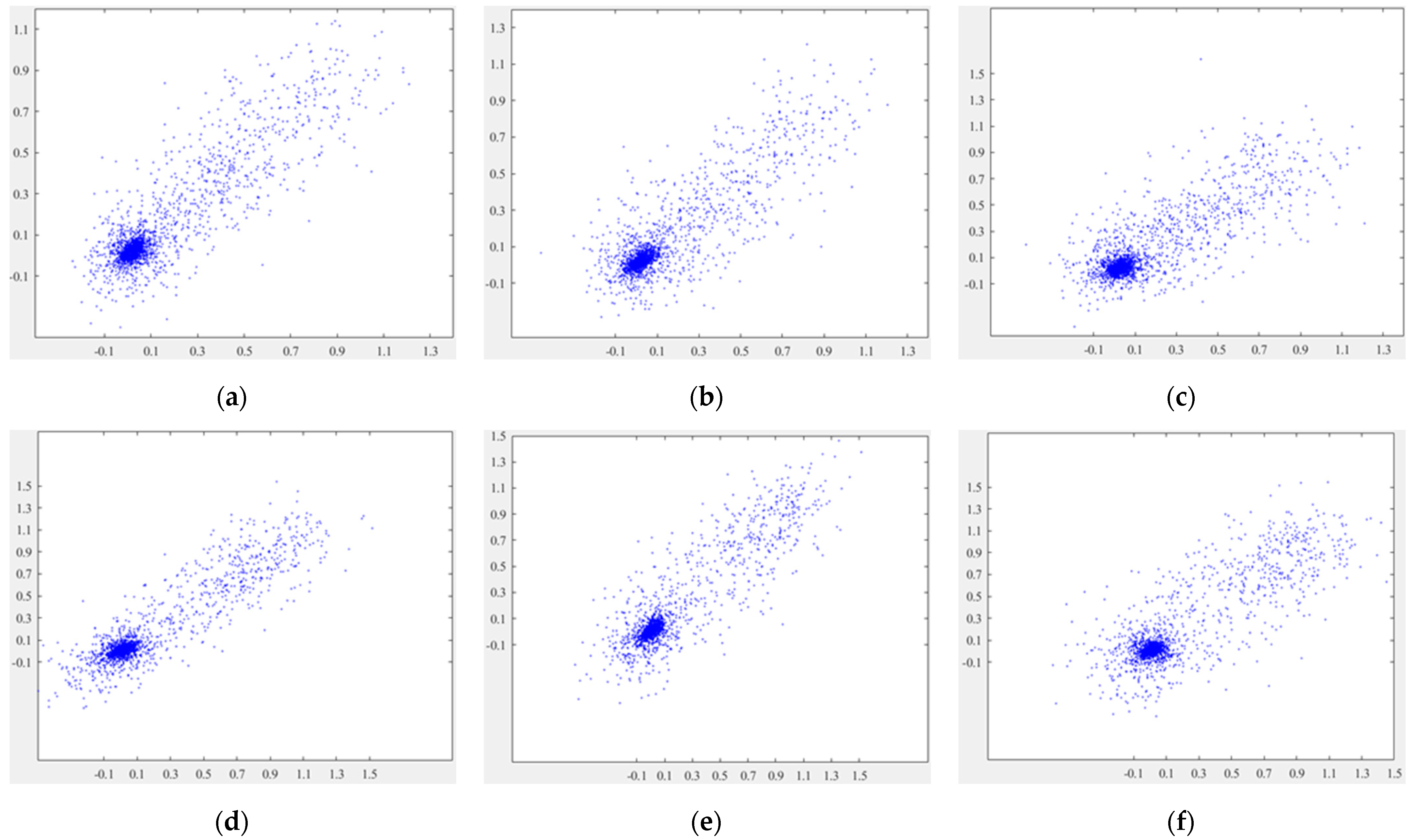
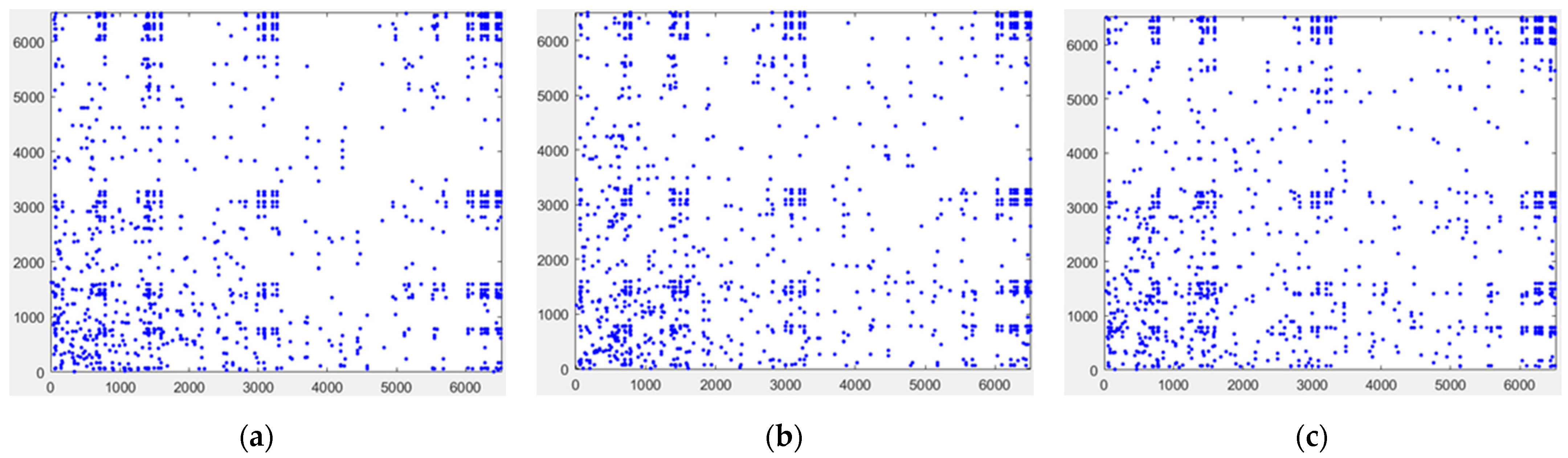
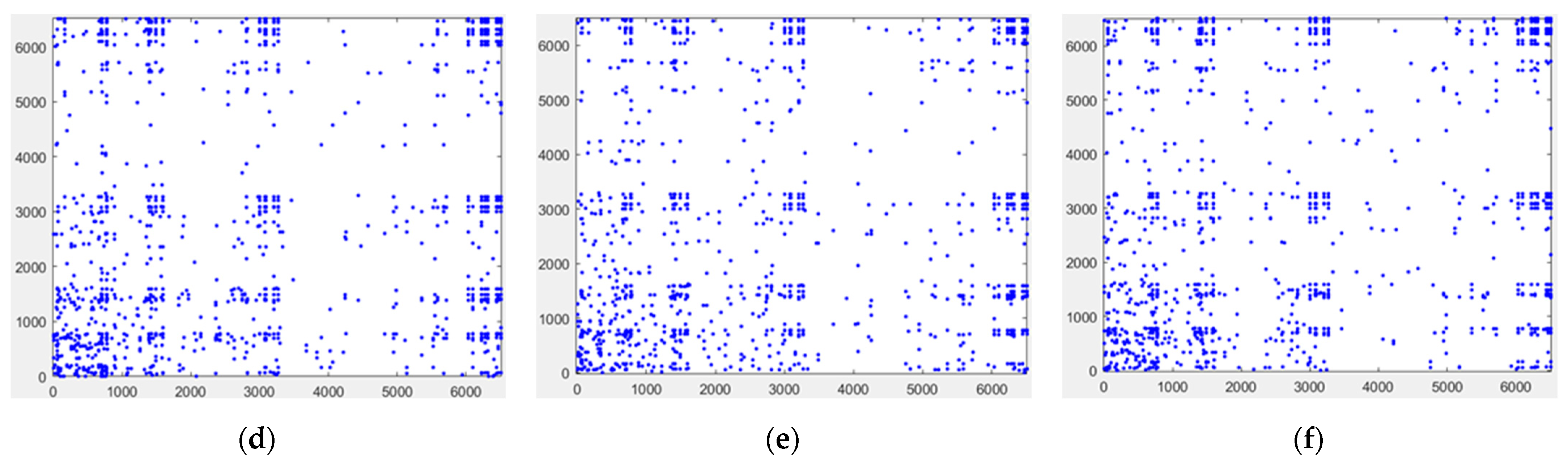
Pixel correlation analysis is an analysis of the high correlation between adjacent pixels of an image. If the correlation is large, one pixel tends to leak information about the other pixels around it, and an attacker can use this characteristic to infer the grayscale value of the next pixel, thus possibly recovering the plaintext. The adjacent pixels in a digital image have similar intensities and therefore a strong correlation. The purpose of encryption is to reduce the correlation of adjacent pixels in an image to prevent the image from being cracked by an attack. For this, we randomly selected 10000 pairs of adjacent pixels in the horizontal, vertical, and diagonal directions and then performed correlation analyses on adjacent pixels of the cosine and sine holograms, which included the plaintext information, as shown in Figure 9. From Figure 9a–f, the correlation between the adjacent pixels of the cosine hologram and the sine hologram is high. The points in these pictures are all basically concentrated on a straight line. Figure 10 shows the adjacent pixel distributions in the horizontal, vertical, and diagonal directions of the cosine sign ciphertext and the sine sign ciphertext. However, as shown in Figure 10a–f, the points in these pictures are more random, indicating that the adjacent pixels of the ciphertext have a weak correlation. Figure 9 and Figure 10 prove that the plaintext information was well encrypted.
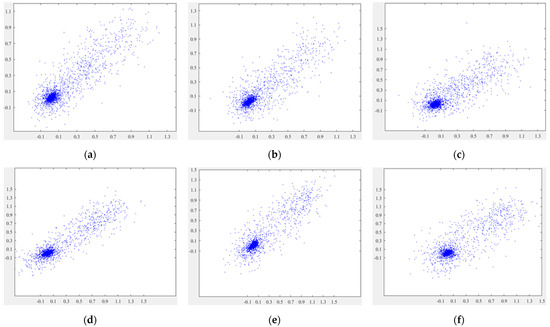
Figure 9.
Adjacent pixel distributions in the horizontal, vertical, and diagonal directions of (a–c) the cosine hologram and (d–f) the sine hologram.
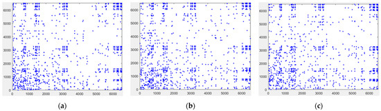
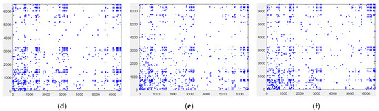
Figure 10.
Adjacent pixel distributions in the horizontal, vertical, and diagonal directions of (a–c) the cosine sign ciphertext and (d–f) the sine sign ciphertext.
We then considered the structural similarity (SSIM). While PSNR is the most common and widely used objective image evaluation index, it is based on the error between the corresponding pixel points and does not consider the visual characteristics of the visual appearance. Therefore, the evaluation results are often inconsistent with the subjective perception of human vision. SSIM is a full-reference image-quality evaluation index that measures image similarity in terms of luminance, contrast, and structure, and it has been widely used in image encryption security analysis. was calculated using Equations (24)–(29).
where and denote the mean values of images and , respectively; and denote the variances of images and ; and denotes the covariance of images and . , , and are constants. To avoid a denominator with a value of 0, they are usually defined as , , and , and, generally, = 0.01, = 0.03, and = 255. takes the value range [0, 1]. The larger the value of , the smaller the image distortion. When two images are identical, the value of is equal to 1. The value between the original image in Figure 5a and Figure 7c is 0.9834. It can be seen that the quality of the decrypted image is good; therefore, the proposed encryption system has high security.
We also analyzed the salt-and-pepper noise pollution of the encrypted hologram. Figure 11a is the decrypted image when the salt-and-pepper noise intensity with variance in Figure 6a,c is 0.01. Figure 11b is the decrypted image when the salt-and-pepper noise intensity variance increases to 0.05. The values of PSNR between the original image and the decrypted images in Figure 11a,b are 63.24 and 18.25, respectively. It can be seen that when the encrypted hologram is subjected to a small amount of salt-and-pepper noise pollution, the decrypted image still has a certain correlation with the original image. It is proved that the proposed encryption system has a certain anti-salt-and-pepper noise attack capability.
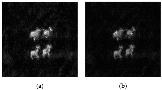
Figure 11.
Salt-and-pepper noise attack analysis: (a) decrypted images with noise intensity with variance of 0.01; (b) decrypted results with noise intensity with variance of 0.05.
7. Conclusions
In this study, an optical scanning hologram was encrypted using the Elgamal algorithm, asymmetrically encrypting both the cosine and sine holograms simultaneously. This approach eliminates the need for key distribution or the risk of plaintext leakage. Our proposed scheme offers a higher security level compared to conventional symmetric optical scanning cryptography systems, as confirmed by simulations and experiments demonstrating its feasibility. The method promises diverse practical real-world applications in the information security field.
Author Contributions
Conceptualization, A.Y. and C.W.; methodology, A.Y.; investigation, Y.D.; writing—original draft preparation, Y.D. and C.W.; writing—review and editing, P.W.M.T. and T.-C.P.; supervision, P.W.M.T. and T.-C.P.; funding acquisition, A.Y. All authors have read and agreed to the published version of the manuscript.
Funding
This research was funded by the National Nature Science Foundation of China, grant number 62075134.
Institutional Review Board Statement
Not applicable.
Informed Consent Statement
Not applicable.
Data Availability Statement
Data are contained with the article.
Conflicts of Interest
The authors declare no conflicts of interest.
References
- Liu, S.; Guo, C.; Sheridan, J.T. Review of optical image encryption techniques. Opt. Laser Technol. 2014, 57, 327–342. [Google Scholar] [CrossRef]
- Choi, K.; Lee, J.-W.; Shin, J.; Hong, K.; Park, J.; Kim, H.-R. Real-time noise-free inline self-interference incoherent digital holography with temporal geometric phase multiplexing. Photonics Res. 2023, 11, 906–913. [Google Scholar] [CrossRef]
- Refregier, P.; Javidi, B. Optical image encryption based on input plane and Fourier plane random encoding. Opt. Lett. 1995, 20, 767–769. [Google Scholar] [CrossRef]
- Deng, H.; Du, Z.; Xiong, J.; Yang, X.; Hua, Y.; Xu, J. Security enhancement for OFDM-UWOC system using three-layer chaotic encryption and chaotic DFT precoding. Chin. Opt. Lett. 2022, 20, 110601. [Google Scholar] [CrossRef]
- Abdurrahman, H.; Yildirim, R. A review of single and multiple optical image encryption techniques. J. Opt. 2021, 23, 113501. [Google Scholar]
- Han, J.W.; Park, C.S.; Ryu, D.H.; Kim, E.-S. Optical image encryption based on XOR operations. Opt. Eng. 1999, 38, 47–54. [Google Scholar] [CrossRef]
- Javidi, B.; Carnicer, A.; Yamaguchi, M.; Nomura, T.; Pérez-Cabré, E.; Millán, M.S.; Nishchal, N.K.; Torroba, R.; Barrera, J.F.; He, W.Q.; et al. Roadmap on optical security. J. Opt. 2016, 18, 083001. [Google Scholar] [CrossRef]
- Zhou, N.; Tong, L.; Zou, W. Multi-image encryption scheme with quaternion discrete fractional Tchebyshev moment transform and cross-coupling operation. Signal Process. 2023, 211, 109107. [Google Scholar] [CrossRef]
- Situ, G.; Zhang, J. Double random-phase encoding in the Fresnel domain. Opt. Lett. 2004, 29, 1584–1586. [Google Scholar] [CrossRef]
- Zafari, M.; Kheradmand, R.; Ahmadi-Kandjani, S. Optical encryption with selective computational ghost imaging. J. Opt 2014, 16, 105405. [Google Scholar] [CrossRef]
- Feng, S.; Xiao, Y.; Yin, W.; Hu, Y.; Li, Y.; Zuo, C.; Chen, Q. Fringe-pattern analysis with ensemble deep learning. Adv. Photonics Nexus 2023, 2, 036010. [Google Scholar] [CrossRef]
- Shan, Z.; Gong, T. JPEG Image Encryption Algorithm Based on DCT Transform. Mod. Comput. 2021, 27, 69–73. [Google Scholar]
- Liu, Z.; Liu, S. Double image encryption based on iterative fractional Fourier transform. Opt. Commun. 2007, 275, 324–329. [Google Scholar] [CrossRef]
- Namias, V. The fractional order Fourier transform and its application to quantum mechanics. IMA J. Appl. Math. 1980, 25, 241–265. [Google Scholar] [CrossRef]
- Xu, X.; Ma, J.; Mo, F.; Ma, Y.; Chen, S.; Wu, J. Three-dimensional information hierarchical encryption based on computer generated hologram and Arnold-Chaos Technology. Laser J. 2018, 39, 66–70. [Google Scholar]
- Gabor, D. Holography, 1948–1971. Science 1972, 177, 299–313. [Google Scholar] [CrossRef]
- Poon, T.-C. Optical Scanning Holography with MATLAB; Springer: Boston, MA, USA, 2007. [Google Scholar]
- Lee, M.; Min, G.; Kim, N.W.; Lee, B.T.; Song, J.-H. Fast Holographic Image Reconstruction Using Phase-Shifting Assisted Depth Detection Scheme for Optical Scanning Holography. ETRI J. 2016, 38, 599–605. [Google Scholar] [CrossRef]
- Tsang, P.W.; Yan, A.; Poon, T.C.; Lam, H. Asymmetrical and biometric encrypted optical scanning holography (ABE-OSH). IEEE Trans. Ind. Inform. 2019, 16, 1094–1101. [Google Scholar] [CrossRef]
- Singh, H.; Khurana, M. An asymmetric optical cryptosystem of double image encryption based on optical vortex phase mask using gyrator transform domain. Recent Adv. Comput. Sci. Commun. 2020, 13, 672–685. [Google Scholar] [CrossRef]
- Al-Shabi, M.A. A survey on symmetric and asymmetric cryptography algorithms in information security. Int. J. Sci. Res. Publ. (IJSRP) 2019, 9, 576–589. [Google Scholar] [CrossRef]
- Kumar, S.S.; Prabhu, S.A.; Durga, R.; Jeevitha, S. A survey on various asymmetric algorithms. J. Adv. Eng. Sci. 2016, 1, 117–119. [Google Scholar]
- Li, W.; Chang, X.; Yan, A.; Zhang, H. Asymmetric multiple image elliptic curve cryptography. Opt. Lasers Eng. 2021, 136, 106319. [Google Scholar] [CrossRef]
- Mallouli, F.; Hellal, A.; Saeed, N.S.; Alzahrani, F.A. A survey on cryptography: Comparative study between RSA vs ECC Algorithms, and RSA vs El-Gamal algorithms. In Proceedings of the 2019 6th IEEE International Conference on Cyber Security and Cloud Computing (CSCloud)/2019 5th IEEE International Conference on Edge Computing and Scalable Cloud (EdgeCom), Paris, Franc, 21–23 June 2019; IEEE: Piscataway, NJ, USA, 2019; pp. 173–176. [Google Scholar]
- Rao, F. On the Security of a Variant of Elgamal Encryption Scheme. IEEE Trans. Dependable Secur. Comput. 2019, 16, 725–728. [Google Scholar] [CrossRef]
- Elgamal, T. A public key cryptosystem and a signature scheme based on discrete logarithms. IEEE Trans. Inf. Theory 1985, 31, 469–472. [Google Scholar] [CrossRef]
- Ye, G.; Jiao, K.; Wu, H.; Pan, C.; Huang, X. An asymmetric image encryption algorithm based on a fractional-order chaotic system and the RSA public key cryptosystem. Int. J. Bifurc. Chaos 2020, 30, 2050233. [Google Scholar] [CrossRef]
- Huang, H.; Yuan, E.; Zhang, D.; Sun, D.; Yang, M.; Zheng, Z.; Zhang, Z.; Gao, L.; Panezai, S.; Qiu, K. Free field of view infrared digital holography for mineral crystallization. Cryst. Growth Des. 2023, 23, 7992–8008. [Google Scholar] [CrossRef]
- Zhang, Y.; Poon, T.-C. Modern Information Optics with MATLAB; Cambridge University Press: Cambridge, UK, 2023. [Google Scholar]


Disclaimer/Publisher’s Note: The statements, opinions and data contained in all publications are solely those of the individual author(s) and contributor(s) and not of MDPI and/or the editor(s). MDPI and/or the editor(s) disclaim responsibility for any injury to people or property resulting from any ideas, methods, instructions or products referred to in the content. |
© 2024 by the authors. Licensee MDPI, Basel, Switzerland. This article is an open access article distributed under the terms and conditions of the Creative Commons Attribution (CC BY) license (https://creativecommons.org/licenses/by/4.0/).