Article

SBS Mitigation by Manipulating the Injecting Polarization Direction in a High-Power Monolithic PM Amplifier

1
Laser Fusion Research Center, China Academy of Engineering Physics, Mianyang 621900, China
2
School of Electronic and Optical Engineering, Nanjing University of Science and Technology, Nanjing 210094, China
3
College of Materials Science and Technology, Nanjing University of Aeronautics and Astronautics, Nanjing 210016, China
*
Authors to whom correspondence should be addressed.
Photonics 2024, 11(9), 890; https://doi.org/10.3390/photonics11090890
Submission received: 31 July 2024 / Revised: 19 September 2024 / Accepted: 19 September 2024 / Published: 21 September 2024
(This article belongs to the Special Issue High-Power Fiber Lasers)

Abstract

:
The polarization direction-dependent SBS threshold was investigated, and the terminal polarization control technique was demonstrated to restore the linear polarization state. By increasing the relative angle of the injecting polarization direction from 0° to 90°, the measured SBS threshold increased until reaching a maximum value, beyond which it decreased in a nearly symmetrical trend. The highest SBS threshold was achieved with the relative polarization angle being 45°, delivering a 67% threshold enhancement compared with that at 0°. A quarter-wave-plate was used to restore the polarization state of the output laser manually from an elliptic to a linearly polarized state, and temperature-dependent polarization fluctuation was observed, which intensified as the laser power was scaled. By reducing the cooling temperature, a 1 kW laser with a linearly polarized state was demonstrated using a 45° polarization direction-injected monolithic PM amplifier.

1. Introduction

High-power monolithic polarization-maintaining (PM) narrow-linewidth fiber amplifiers, which can deliver near-diffraction limitation laser beams, have been employed in versatile applications, such as coherent beam combination, nonlinear frequency conversion, gravitational wave detection, and so on [1,2,3]. Thanks to the tremendous development of double-clad fiber technology and high-brightness diode pump sources, monolithic PM fiber amplifiers have soared dramatically, and a multi-kW laser with high beam quality has been achieved [4,5,6,7,8]. Stimulated Brillouin scattering (SBS) is the primary limiting factor for the power scaling of narrow-linewidth PM fiber amplifiers, which causes the forward-transmitted signal light transfers nonlinearly to the backward propagating Stokes light and produce catastrophic giant pulses to destroy the laser systems [2,9,10,11]. Due to its far-reaching impact, SBS is always under intense research, and many strategies have been reported to suppress SBS, such as using large mode area (LMA) fibers [12], reducing fiber length [13], applying phase-modulated seed [14], introducing temperature or stress gradients [15], and so on. Most of the aforementioned strategies require sophisticated modification of the laser system, which causes the sacrifice of either cost or performance. It is well known that polarization plays an important role in the SBS effect, which is one of the most important properties for high-power monolithic PM fiber amplifiers [16,17]. Researchers have exploited this unique property to suppress SBS. In 2005, Spring et al. [18] reported that the measured SBS threshold was improved from 148.3 mW to 293.5 mW by changing injecting polarization direction in two Lightwave Electronics NPRO Nd:YAG lasers. In 2014, Guintrand et al. [19] reported that the back-reflected power had 90° periodicity dependence versus linear output polarization direction and the back-reflected power was lowest when the output linear polarization angle was 45°. However, little work on high-power monolithic PM narrow-linewidth fiber amplifiers has been reported. For high-power fiber lasers in monolithic format, there are large temperature gradients and longer nonlinear interaction length, which impact the onset of SBS and may result in deviation of polarization-dependent SBS behavior. In 2023, Liao et al. suppressed SBS by changing the splicing angle of the PM fiber from 0° to 45° [20], but the detailed trend of the polarization-dependent SBS has not been investigated. In addition, the polarization extinction ratio (PER) degraded from 19 dB to 7 dB, which meant that the output laser was no longer a linearly polarized beam, and that the application was limited.
This paper presents an investigation involving manipulating polarization direction to mitigate SBS while ensuring the linearly polarized light in monolithic PM fiber laser amplifiers. By changing the polarization direction of the injected beam, the SBS behavior in high-power monolithic PM fiber amplifiers was investigated, and a quarter-wave-plate (QWP) was applied to the output laser to restore it to linearly polarized light. Temperature-dependent polarization fluctuation was also investigated.

2. Experimental Setup

The monolithic high-power PM amplifier with narrow linewidth was set up as shown in Figure 1. Generally, a laser with a linewidth less than 0.3 nm is referred to as a narrow-linewidth laser [21,22,23,24]. A single-frequency fiber laser centered at 1064 nm served as a seed laser, which was broadened to 11.5 GHz (0.043 nm) to suppress SBS [25]. A two-stage forward-pump pre-amplifier was employed to boost the broadened seed light to 19 W. A three-port isolator (ISO) was applied to block the detrimental backward Stokes light generated by SBS, and the third port of the ISO was used to monitor the occurrence of SBS and detrimental pulsing. Then, a mode field adapter (MFA) was employed to avoid the adverse influence induced by the unmatched mode field between the pre-amplifier fiber and the main amplifier fiber [26]. The main amplifier fiber consisted of a piece of 10 m PM-YDF (polarization-maintained ytterbium-doped-fiber) with a core size of 20 μm and a cladding size of 400 μm, which was counter-pumped by five wavelength-locked 976 nm laser diodes (LDs) via a backward (6 + 1) × 1 signal and pump combiner. Two homemade cladding power strippers (CPSs) were employed in the input and output port of the main amplifier to wipe off the cladding signal lightand the residual pump power from the main amplifier [27]. A counter-pump configuration was utilized for mitigating SBS and transverse mode instability (TMI) [28], and the active fibers were coiled tightly with a bending diameter of 10 cm for enhancing the loss of high-order modes to alleviate the limitation of TMI [29]. A water-cooled plate was employed to dissipate the waste heat produced in the laser system. A piece of passive fiber with an anti-reflection coated quartz beam head (QBH) and a collimator was utilized to deliver the amplified laser into free space safely. The polarization extinction ratio (PER) was determined as 10log(Power 1/Power 2) by a half-wave plate (HWP) and a polarizer [30]. Due to the characteristics of PM fibers, the direction of polarization state can be controlled by changing the direction of the slow axis. A commercial fusion splicer was used to realize the rotation of incident polarization direction. First, the PM fiber was clamped to the fixture with the motor. After the fibers were aligned, the fibers were rotated at a specific angle by manipulating the motors as shown in Figure 1. Then, the fibers were spliced together, and the incident polarization direction was manipulated.
The output laser characteristics were measured after a beam splitting system, as shown in Figure 1. It consisted of a power meter with a measurement accuracy of ±5%, an optical spectrum analyzer (OSA) with a resolution of 0.02 nm, a QWP, and a polarization analyzer (PA), with sample rate being 60 Hz. For the measurement of output power, the power is recorded when it is stable, and it is rounded properly using the measurement accuracy of the power meter. When beam quality is measured, a commercial beam quality analyzer is employed, and the measurement accuracy is ±5%. To control the measurement error, an appropriate measurement length is chosen. The measurement accuracy of a polarization analyzer includes an azimuth accuracy of ±0.25°, ellipticity accuracy of ±0.25°, and degree of polarization (DOP) accuracy of ±1.0%. The Stokes components on the Poincaré sphere are calculated by the polarization analyzer; thus, the evolution of polarization instability can be correctly exhibited on the Poincaré sphere. It was known that the wedge plates had a different reflectance for different polarization states of light due to reflection, so the incident angles were controlled below 5° to keep the polarization state of the split light the same as that of the output light.

3. Experimental Results

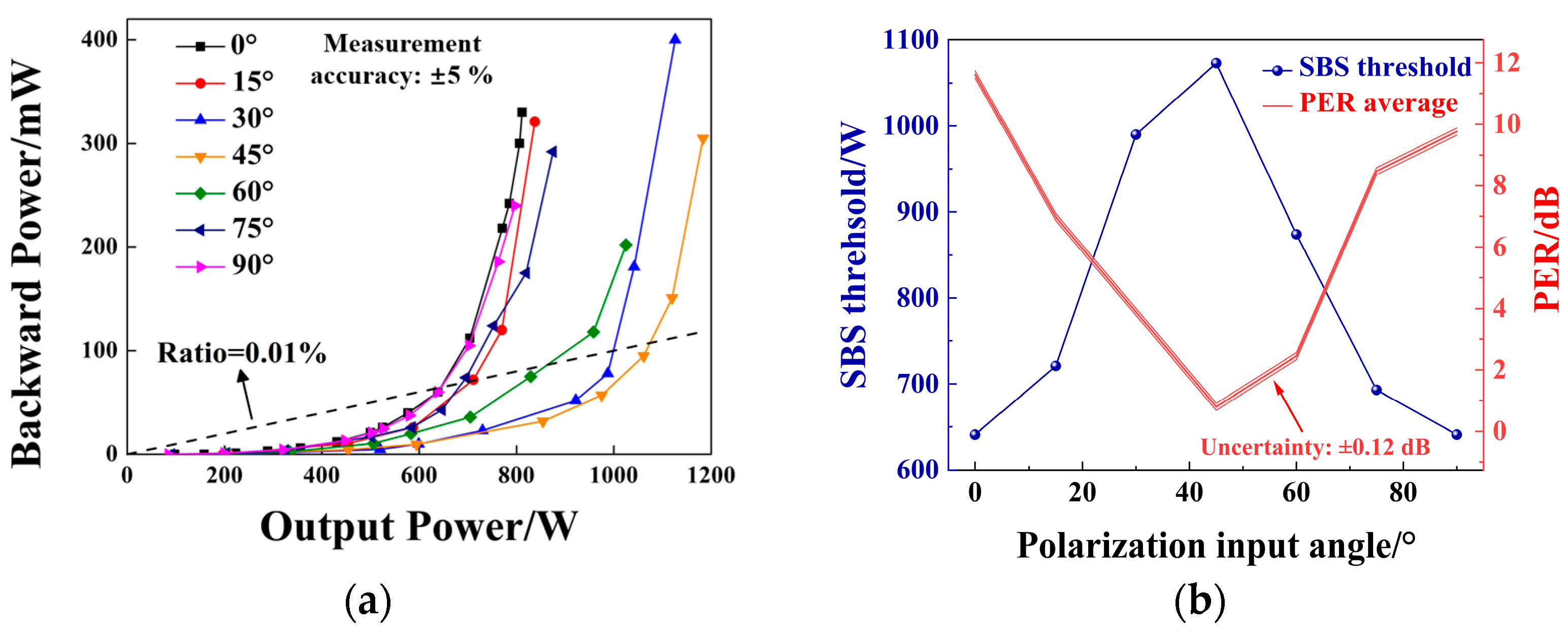
Polarization-direction-dependent SBS behavior was studied in a monolithic high-power PM amplifier, which is shown in Figure 2. In Figure 2a, the backward laser power versus the output laser power under different polarization input angles were measured; a dashed line has been added, which corresponds to the backward power ratio, which was 0.01%, which was calculated using P o w e r   r a t i o = P b a c k w a r d p o u t p u t . Output laser power with a backward power ratio of 0.01% has been defined as the SBS threshold [31]. One can see that, as the output power grows, the backward light power shows an overall non-linear increase, starting to grow rapidly after a certain threshold has been exceeded. In Figure 2b, SBS thresholds and PERs with different polarization directions have been plotted. When the polarization injecting angle was 0°, which means the polarization direction was parallel to the slow axis in the PM fiber, the SBS threshold was measured to be 641 W, while the PER was 11.2 dB. By increasing the relative angle of the slow axis between the output PM fiber of the MFA and the input PM fiber of the CPS from 0° to 90°, the polarization direction in the main amplifier changed synchronously, and the measured SBS threshold increased monotonically until reaching a maximum value, beyond which it decreased in a nearly symmetrical trend. The highest SBS threshold of 1073 W was reached with the polarization angle being 45°, delivering a threshold enhancement of 67% compared with that at 0°. This was due to the fact that the fast axis and slow axis in PM fibers were different [18], and the Brillouin gain spectra were broadened in the case where the polarization angle was set to 45°, where half of the signal light in the fiber core was transmitted along the slow axis while the other half along the fast axis. Although the SBS had been mitigated, the PER of the output beam was reduced to a fluctuation state with a minimum value of 0.8 dB, which was affected by external temperature fluctuation or vibration in the laboratory environment. Concerns with the power meter caused an uncertainty in the exact calculation of the PER. The PER uncertainty was calculated and shown in Figure 2b, which was ±0.12 dB.
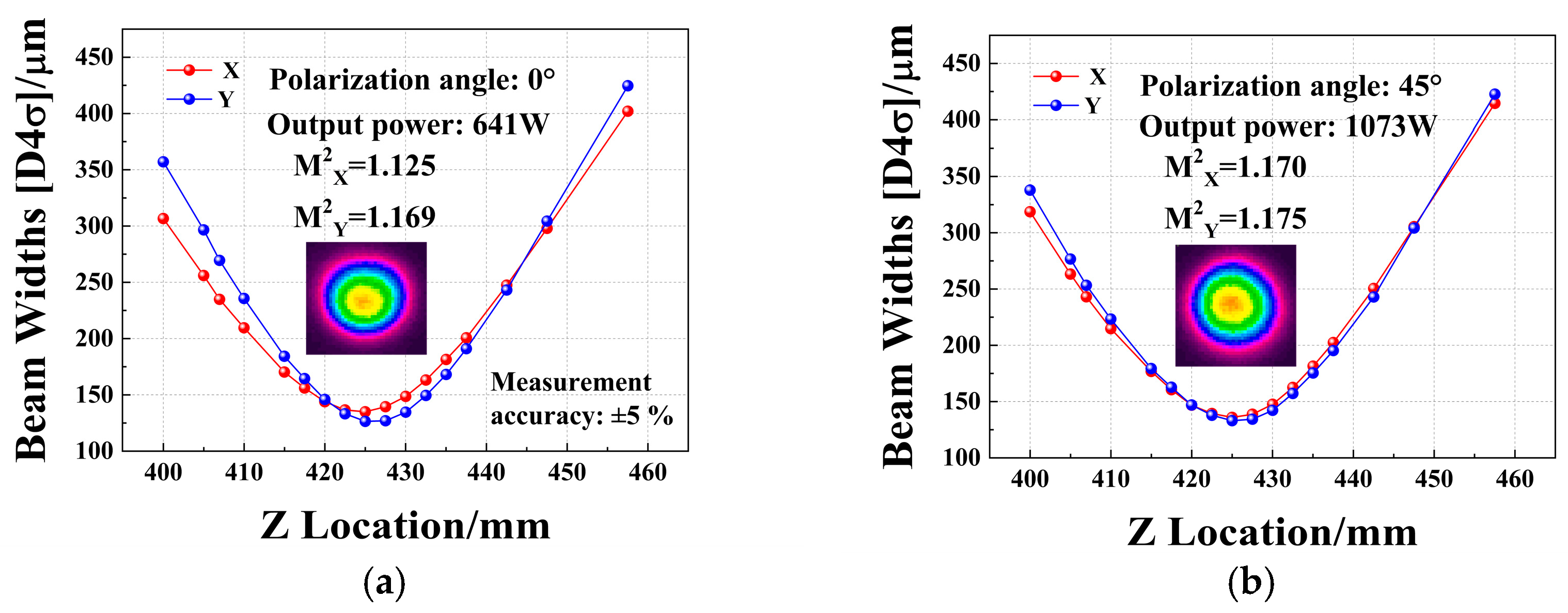
Due to the polarization angle between the PM fibers, there is mismatch at the splicing point, and the influence of the mismatch on beam quality has been measured. In Figure 3, the beam quality M2 factor was shown for different polarization angles and output power. As shown in Figure 3a, beam quality with a polarization angle of 0° maintainednear-diffraction-limit, and the mode distortion induced did not occur at the SBS threshold. When the output power was improved to 1073 W by manipulating the polarization angle to 45°, the measured beam quality in the X direction and Y direction was M2X = 1.170 and M2Y = 1.175 respectively, which means that the introduction of the splicing offset angle had a negligible impact on the beam quality, as shown in Figure 3b.
The polarization states of the output beam were measured under output power of 500 W when the polarization angle was 45°, which is shown in Figure 4a. One can see that the position of the polarization state is located in the upper half of the sphere, which means that the output beam was an elliptic polarized beam. The normalized Stokes components were measured during a time period of 30 s, as shown in Figure 4b. One can see that S1 had a slow fluctuation at the level of a second, while S2 and S3 varied slightly. So, the output beams would become linearly polarized beams by employing a QWP through manual rotation. For many applications [32,33,34], narrow-linewidth lasers with linearly polarized state are required, which limits the applicability of the proposed method to mitigating SBS. It is necessary to investigate whether the high-power lasers with degraded PERs are reversible. Therefore, the work in part 2 was carried out, which is important for the application of the proposed mitigating strategy.
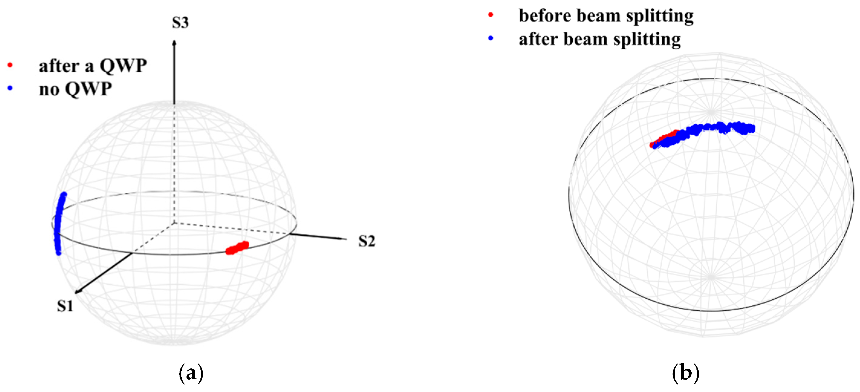
As a preliminary demonstration, polarization control was employed at under 3 mW, the results of which are shown in Figure 5. As shown in Figure 5a, when the output beam did not pass through the QWP, the location on the Poincaré sphere determined by three Stokes components was time-varying and not distributed around the equator, which means that the polarization state of the output beam was not linearly polarized. As the output laser passed through a QWP at certain incident angle, it was clear that the position of the polarization states on the Poincaré sphere remained basically on the equator, and did not change significantly for a period time of 30 s. That result proves that the terminal polarization controlling strategy worked. However, due to the limited damage threshold of the available QWP in our lab, a higher power demonstration could not be carried out by employing the QWP directly on the output laser. A beam splitting system was assembled, and the incident angle of each beam splitting plate was below 5° to avoid polarization state changes before and after the beam splitting. The polarization states before and after the beam splitting system are shown in Figure 5b. One can see that both the polarization states remained in a similar area and that the location of the polarization states after the beam splitting system moved more, while the small offset could be considered as due to the influence of the beam splitting plate, although the incident angle was below 5°. Hence, polarization state variation was negligible before and after the beam splitting, and the low-power polarization state variation after the beam splitting was the same as the high-power laser, which means that the conversion of polarization state could be verified at lower power.
The polarization states of the low-power beam after beam splitting at different levels of output power are shown in Figure 6. When only the pre-amplifiers were operating and the output power was 15 W, the position of the polarization states remained around the equator and kept stable for a period time of >30 s after the adjusting of the QWP. Then, the pump LD of the main amplifier was turned on, and the polarization states at different power were monitored. As the output power increased to 100 W, the polarization states were still maintained around the equator by rotating the QWP incident angle to a certain angle. However, when the output power increased to 500 W, the polarization states could not be controlled to a linearly polarized one by manually rotating the QWP. It was known that, as more pump power was launched into the main amplifier, more heat was generated by the quantum defect of ytterbium ion gain, which intensified the heat noise and caused severe polarization fluctuation. To quantitatively analyze the degree of polarization instability due to the accumulation of waste heat induced by fiber gain, the degree of polarization instability (a definition for measuring the degree of polarization instability used in this work) and standard deviation (SD) of position were simulated under different output power and cooled water temperatures. When the cooled water temperature was 20 °C, the position of the polarization states remained around the equator and the SD was 0.011 and 0.005 under output power of 15 W and 100 W, respectively. But as the output power reached 500 W, the SD increased suddenly to 0.287, which was clearly higher than that at 100 W. Meanwhile, the ratio of degree of polarization instability also showed a similar trend for polarization instability. When the output power was 15 W and 100 W, the ratio of degree of polarization instability maintained was 0 in both cases, until the output power reached 500 W and it became 0.999. This indicated that the degree of polarization instability was high. It was hard to control the intensified polarization fluctuation by manually adjustment.
To remove the detrimental waste heat, the amplifier cooling temperature was reduced to 3 °C to enhance heat dissipation efficiency. Polarization states on Poincaré sphere at different output power with the main amplifier cooled to a temperature of 3 °C are shown in Figure 7. As shown in Figure 7, the polarization states at 500 W were easily controlled when the cooling temperature of the amplifier was reduced to 3 °C, and their location on the Poincaré sphere remained around the equator during a period time of 30 s with SD being 0.036 and the ratio of degree of polarization instability being 0, which means that polarization fluctuation was dependent on the waste heat in the main amplifier. As the output power increased to 1 kW, the heat noise intensified, and the polarization began to fluctuate, but the SD was still below 0.2, and the ratio of degree of polarization instability was 0.334, which means that more efficient heat management was required. In addition, automatic control systems with a feedback algorithm should be employed to suppress the fluctuation and stabilize the polarization [35].

4. Discussion

From the previous experimental results, one can conclude that SBS effect can be significantly suppressed by changing the incident polarization direction of the beam. In Stolen’s results [16], the maximal output power was 1.29 W, whereas the maximal output power was 1071 W in our results. The big difference between them means that the different temperature gradient was induced by Yb gain, which has much impact on the SBS threshold. Thus the different temperature gradient might lead to the magnitude of variation of 67%, which is below the results in Stolen’s work. A comparison between the existing SBS suppression strategies and our work is shown in Table 1. Generally, many of the strategies listed in the table are not independent, i.e., they can be used in combination to deliver a higher output power laser in a fiber laser amplifier.
According to Table 1, one can note that, while the SBS suppression of 67% was realized in this work, the output light was not a linearly polarized light. To restore the output beam to a linearly polarized light, the terminal polarization control strategy of an interpolated QWP was demonstrated manually, which was carried out on the low-level light sampled from the kW-level main laser, for considerations of operation safety. At present, lasers of several kilowatts can be handled by a QWP, so a high-power laser can be injected into the QWP. With the rapid development of automatic control technology, optical elements with automatic control are feasible, which means that the QWP can be manipulated automatically. There are many optimizing algorithms to control the automatic QWP to compensate for the problems of low control rate and control instability. With the combination of a high-damage QWP and automatic control system, higher power laser with a linearly polarized state can be delivered.

5. Conclusions

In this work, the impact of the polarization direction on SBS and a mitigation strategy using terminal polarization control were investigated. Firstly, an all-fiber PM amplifier was assembled and a spliced offset angle was introduced to change the polarization direction. The polarization direction-dependent SBS threshold was observed, and the SBS threshold reached its highest as the polarization angle was set to 45°. It showed an improvement of 67% compared to the polarization angle of 0°, but the PER of the output light was below 1 dB. Further, terminal polarization control was employed using a QWP, and the results show that the polarization states after using the QWP were restored to a linear polarization state by properly adjusting the QWP. Finally, the mitigation of SBS and the polarization control were both realized at 1 kW.

Author Contributions

Conceptualization, Y.W., Q.C. and C.Z.; methodology, R.T., C.L. and C.Z.; validation, Q.C. and R.T.; formal analysis, Y.W., Q.C. and R.T.; investigation, Y.W., L.H. and Y.Z.; data curation, Y.W.; writing—original draft preparation, Y.W.; writing—review and editing, R.T.; visualization, Y.W.; supervision, H.Z. and H.L.; project administration, J.W. All authors have read and agreed to the published version of the manuscript.

Funding

This work was supported by the National Natural Science Foundation of China (No. 62205317).

Institutional Review Board Statement

Not applicable.

Informed Consent Statement

Not applicable.

Data Availability Statement

Data is contained within the article.

Conflicts of Interest

The authors declare no conflicts of interest.

References

  1. Jauregui, C.; Limpert, J.; Tünnermann, A. High-Power Fibre Lasers. Nat. Photonics 2013, 7, 861–867. [Google Scholar] [CrossRef]
  2. Zervas, M.N.; Codemard, C.A. High Power Fiber Lasers: A Review. IEEE J. Sel. Top. Quantum Electron. 2014, 20, 219–241. [Google Scholar] [CrossRef]
  3. Zhou, P.; Ma, P.; Ren, S.; Chen, Y.; Liu, W.; Yao, T.; Pan, Z.; Chen, J. High-power narrow linewidth fiber laser: Progress and prospect. Inf. Countermeas. Technol. 2023, 2, 16–36. [Google Scholar]
  4. Tao, R.; Ma, P.; Wang, X.; Zhou, P.; Liu, Z. 13 kW Monolithic Linearly Polarized Single-Mode Master Oscillator Power Amplifier and Strategies for Mitigating Mode Instabilities. Photonics Res. 2015, 3, 86–93. [Google Scholar] [CrossRef]
  5. Ren, S.; Ma, P.; Chen, Y.; Li, W.; Wang, G.; Liu, W.; Huang, L.; Pan, Z.; Yao, T.; Zhou, P. 5 kW-level narrow linewidth fiber laser output realized by homemade polarization-maintained fiber. Infrared Laser Eng. 2023, 52, 20220900. [Google Scholar]
  6. Wang, Y.; Peng, W.; Liu, H.; Yang, X.; Yu, H.; Wang, Y.; Wang, J.; Feng, Y.; Sun, Y.; Ma, Y.; et al. Linearly Polarized Fiber Amplifier with Narrow Linewidth of 5 kW Exhibiting a Record Output Power and Near-Diffraction-Limited Beam Quality. Opt. Lett. 2023, 48, 2909–2912. [Google Scholar] [CrossRef]
  7. Chu, Q.; Shu, Q.; Li, F.; Guo, C.; Yan, Y.; Zhang, H.; Liu, Y.; Tao, R.; Lin, H.; Wang, J. Power Scaling of High-Power Linearly Polarized Fiber Lasers with <10 GHz Linewidth. Front. Phys. 2023, 11, 1198305. [Google Scholar]
  8. Liao, S.; Luo, T.; Xiao, R.; Shu, C.; Cheng, J.; Zhang, Z.; Xing, Y.; Li, H.; Dai, N.; Li, J. 4.6 kW Linearly Polarized and Narrow-Linewidth Monolithic Fiber Amplifier Based on a Fiber Oscillator Laser Seed. Opt. Lett. 2023, 48, 6533–6536. [Google Scholar] [CrossRef]
  9. Ippen, E.P.; Stolen, R.H. Stimulated Brillouin Scattering in Optical Fibers. Appl. Phys. Lett. 1972, 21, 539–541. [Google Scholar] [CrossRef]
  10. Zha, C.; Peng, W.; Wang, X.; Wang, Y.; Li, T.; Ma, Y.; Zhang, K.; Feng, Y.; Peng, J.; Sun, Y. Self-Pulsing in Kilowatt Level Narrow-Linewidth Fiber Amplifier with WNS Phase-Modulation. Opt. Express 2017, 25, 19740–19741. [Google Scholar] [CrossRef]
  11. Cui, J.; Dang, H.; Feng, K.; Yang, W.; Geng, T.; Hu, Y.; Zhang, Y.; Jiang, D.; Chen, X.; Tan, J. Stimulated Brillouin Scattering Evolution and Suppression in an Integrated Stimulated Thermal Rayleigh Scattering-Based Fiber Laser. Photonics Res. 2017, 5, 233–238. [Google Scholar] [CrossRef]
  12. Ma, P.; Zhou, P.; Ma, Y.; Su, R.; Xu, X.; Liu, Z. Single-Frequency 332 W, Linearly Polarized Yb-Doped All-Fiber Amplifier with near Diffraction-Limited Beam Quality. Appl. Opt. 2013, 52, 4854–4857. [Google Scholar] [CrossRef]
  13. Theeg, T.; Sayinc, H.; Neumann, J.; Kracht, D. All-Fiber Counter-Propagation Pumped Single Frequency Amplifier Stage with 300-W Output Power. IEEE Photonics Technol. Lett. 2012, 24, 1864–1867. [Google Scholar] [CrossRef]
  14. Chang, Z.; Wang, Y.; Sun, Y.; Peng, W.; Ke, W.; Ma, Y.; Zhu, R.; Tang, C. 15 kW Polarization-Maintained Yb-Doped Amplifier with 13 GHz Linewidth by Suppressing the Self-Pulsing and Stimulated Brillouin Scattering. Appl. Opt. 2019, 58, 6419–6425. [Google Scholar] [CrossRef] [PubMed]
  15. Huang, L.; Wu, H.; Li, R.; Li, L.; Ma, P.; Wang, X.; Leng, J.; Zhou, P. 414 W Near-Diffraction-Limited All-Fiberized Single-Frequency Polarization-Maintained Fiber Amplifier. Opt. Lett. 2017, 42, 1–4. [Google Scholar] [CrossRef] [PubMed]
  16. Stolen, R. Polarization Effects in Fiber Raman and Brillouin Lasers. IEEE J. Quantum Electron. 1979, 15, 1157–1160. [Google Scholar] [CrossRef]
  17. Agrawal, G.P. Nonlinear Fiber Optics, 6th ed.; Academic Press: London, UK, 2019; pp. 361–362. [Google Scholar]
  18. Spring, J.B.; Russell, T.H.; Shay, T.M.; Berdine, R.W.; Sanchez, A.D.; Ward, B.G.; Roh, W.B. Comparison of Stimulated Brillouin Scattering Thresholds and Spectra in Nonpolarization-Maintaining and Polarization-Maintaining Passive Fibers. In Fiber Lasers II: Technology, Systems, and Application, Proceedings of the Lasers and Applications in Science and Engineering, San Jose, CA, USA, 22–27 January 2005; Durvasula, L.N., Brown, A.J.W., Nilsson, J., Eds.; SPIE: Bellingham, WA, USA, 2005; p. 147. [Google Scholar]
  19. Guintrand, C.; Edgecumbe, J.; Farley, K.; Abramczyk, J.; Tankala, K. Stimulated Brillouin Scattering Threshold Variations due to Bend-Induced Birefringence in a Non-Polarization-Maintaining Fiber Amplifier. In Proceedings of the CLEO: 2014, San Jose, CA, USA, 8–13 June 2014; JW2A.23; OSA: Washington, DC, USA, 2014. [Google Scholar]
  20. Liao, S.; Luo, T.; Xiao, R.; Zhang, Z.; Xing, Y.; Chu, Y.; Li, H.; Peng, J.; Dai, N.; Li, J. Stimulated Brillouin Scattering Induced Mode Degradation in High-Power Narrow-Linewidth Linearly Polarized Fiber Amplifiers. Opt. Laser Technol. 2023, 162, 109286. [Google Scholar] [CrossRef]
  21. Naderi, N.A.; Flores, A.; Anderson, B.M.; Dajani, I. Beam Combinable, Kilowatt, All-Fiber Amplifier Based on Phase-Modulated Laser Gain Competition. Opt. Lett. 2016, 41, 3964–3967. [Google Scholar] [CrossRef]
  22. Beier, F.; Hupel, C.; Kuhn, S.; Hein, S.; Nold, J.; Proske, F.; Liem, A.; Jauregui, C.; Limpert, J.; Haarlammert, N.; et al. Single Mode 4.3 kW Output Power from a Diode-Pumped Yb-Doped Fiber Amplifier. Opt. Express 2017, 25, 14892–14899. [Google Scholar] [CrossRef]
  23. Meng, D.; Lai, W.; He, X.; Ma, P.; Su, R.; Zhou, P.; Yang, L. Kilowatt-Level, Mode-Instability-Free, All-Fiber and Polarization-Maintained Amplifier with Spectral Linewidth of 1.8 GHz. Laser Phys. 2019, 29, 035103. [Google Scholar] [CrossRef]
  24. Lin, H.; Tao, R.; Li, C.; Wang, B.; Guo, C.; Shu, Q.; Xu, L.; Wang, J.; Jing, F.; Chu, Q. 3.7 kW Monolithic Narrow Linewidth Single Mode Fiber Laser through Simultaneously Suppressing Nonlinear Effects and Mode Instability. Opt. Express 2019, 27, 9716–9724. [Google Scholar] [CrossRef] [PubMed]
  25. Zeringue, C.; Dajani, I.; Naderi, S.; Moore, G.T.; Robin, C. A Theoretical Study of Transient Stimulated Brillouin Scattering in Optical Fibers Seeded with Phase-Modulated Light. Opt. Express 2012, 20, 21196–21213. [Google Scholar] [CrossRef] [PubMed]
  26. Ko, P.; Písa, M. Mode-Field Adapter for Tapered-Fiber-Bundle Signal and Pump Combiners. Appl. Opt. 2015, 54, 751–756. [Google Scholar]
  27. Zou, S.; Chen, H.; Zhang, J.; Yu, H.; Zhang, Z.; Sun, J.; Lin, X. Cladding Light Stripper of High Average Stripped Power Density with High Attenuation of 39 dB and Low Temperature Rise. IEEE Photonics J. 2018, 10, 7100610. [Google Scholar] [CrossRef]
  28. Tao, R.; Ma, P.; Wang, X.; Zhou, P.; Liu, Z. Theoretical Study of Pump Power Distribution on Modal Instabilities in High Power Fiber Amplifiers. Laser Phys. Lett. 2017, 14, 025002. [Google Scholar] [CrossRef]
  29. Tao, R.; Wang, X.; Zhou, P. Comprehensive Theoretical Study of Mode Instability in High-Power Fiber Lasers by Employing a Universal Model and Its Implications. IEEE J. Sel. Top. Quantum Electron. 2018, 24, 1–19. [Google Scholar] [CrossRef]
  30. Ma, H.; Yuan, X.; Zhang, Y.; Hong, Y.; Wang, L.; Zhang, Y. A Novel Measurement Scheme of the Polarization Extinction Ratio. In Proceedings of the 2015 International Conference on Optical Instruments and Technology: Advanced Lasers and Applications, Beijing, China, 17–19 May 2015; Zhu, J., Gao, C., Eds.; SPIE: Bellingham, WA, USA, 2015; p. 962108. [Google Scholar]
  31. Xie, W.; Yang, Y.; Wang, H.; Wang, K.; Duan, X.; Liu, K.; Chen, X.; Xiong, X.; Zhang, D.; Meng, J. 3.05 kW, 13.7 GHz Linewidth Fiber Amplifier Based on PRBS Phase Modulation for SBS Suppression. Appl. Opt. 2024, 63, 2994–3002. [Google Scholar] [CrossRef]
  32. Yang, F.; Ye, Q.; Pan, Z.; Chen, D.; Cai, H.; Qu, R.; Yang, Z.; Zhang, Q. 100-mW Linear Polarization Single-Frequency All-Fiber Seed Laser for Coherent Doppler Lidar Application. Opt. Commun. 2012, 285, 149–152. [Google Scholar] [CrossRef]
  33. Beier, F.; Möller, F.; Sattler, B.; Nold, J.; Liem, A.; Hupel, C.; Kuhn, S.; Hein, S.; Haarlammert, N.; Schreiber, T.; et al. Experimental Investigations on the TMI Thresholds of Low-NA Yb-Doped Single-Mode Fibers. Opt. Lett. 2018, 43, 1291–1294. [Google Scholar] [CrossRef]
  34. Taylor, L.R.; Feng, Y.; Calia, D.B. 50W CW Visible Laser Source at 589 nm Obtained via Frequency Doubling of Three Coherently Combined Narrow-Band Raman Fibre Amplifiers. Opt. Express 2010, 18, 8540–8555. [Google Scholar] [CrossRef]
  35. Jiang, M.; Wu, H.; An, Y.; Hou, T.; Chang, Q.; Huang, L.; Li, J.; Su, R.; Zhou, P. Fiber Laser Development Enabled by Machine Learning: Review and Prospect. PhotoniX 2022, 3, 16. [Google Scholar] [CrossRef]
  36. Shiraki, K.; Ohashi, M.; Tateda, M. Suppression of stimulated Brillouin scattering in a fibre by changing the core radius. Electron. Lett. 1995, 31, 668–669. [Google Scholar] [CrossRef]
  37. Kobyakov, A.; Kumar, S.; Chowdhury, D.Q.; Ruffin, A.B.; Sauer, M.; Bickham, S.R.; Mishra, R. Design Concept for Optical Fibers with Enhanced SBS Threshold. Opt. Express 2005, 13, 5338–5346. [Google Scholar] [CrossRef] [PubMed]
  38. Shiraki, K.; Ohashi, M.; Tateda, M. SBS Threshold of a Fiber with a Brillouin Frequency Shift Distribution. J. Light. Technol. 1996, 14, 50–57. [Google Scholar] [CrossRef]
  39. Wang, X.; Zhou, P.; Leng, J.; Du, W.; Ma, Y.; Xiao, H.; Zhu, J.; Dong, X.; Xu, X.; Liu, Z.; et al. A 275-W Multitone Driven All-Fiber Amplifier Seeded by a Phase-Modulated Single-Frequency Laser for Coherent Beam Combining. IEEE Photonics Technol. Lett. 2011, 23, 980–982. [Google Scholar] [CrossRef]
  40. Li, W.; Yan, Z.; Ren, S.; Deng, Y.; Chen, Y.; Ma, P.; Huang, L.; Pan, Z.; Zhou, P.; Si, L. Confined-Doped Active Fiber Enabled All-Fiber High-Power Single-Frequency Laser. IEEE Photonics Technol. Lett. 1993, 5, 1335–1337. [Google Scholar] [CrossRef]
  41. Imai, Y.; Shimada, N. Dependence of Stimulated Brillouin Scattering on Temperature Distribution in Polarization-Maintaining Fibers. IEEE Photonics Technol. Lett. 1993, 5, 1335–1337. [Google Scholar] [CrossRef]
  42. Yoshizawa, N.; Imai, T. Stimulated Brillouin Scattering Suppression by Means of Applying Strain Distribution to Fiber with Cabling. J. Light. Technol. 1993, 11, 1518–1522. [Google Scholar] [CrossRef]
Figure 1. Experimental setup of the high-power monolithic PM laser (SF: single frequency, SBM: spectrum-broadening module, MFA: mode field adapter, CPS: cladding power stripper, LD: laser diode, QBH: quartz blockhead, HWP: half-wave plate).
Photonics 11 00890 g001
Figure 2. (a) Backward light power versus output power, and (b) the SBS thresholds and PERs at different polarization input angles.
Photonics 11 00890 g002
Figure 3. Beam quality (a) with a polarization angle of 0° and output power of 641 W, and (b) with a polarization angle of 45°and output power of 1073 W.
Photonics 11 00890 g003
Figure 4. (a) The polarization states of the output beam on the Poincaré sphere, and (b) the normalized Stokes components versus time at the output power of 500 W.
Photonics 11 00890 g004
Figure 5. (a) The beam polarization states before and after a QWP, and (b) the polarization states before and after the beam splitting system.
Photonics 11 00890 g005
Figure 6. Polarization states on the Poincaré sphere at different output power with the main amplifier cooled to a temperature of 20 °C.
Photonics 11 00890 g006
Figure 7. Polarization states on the Poincaré sphere at different output power with the main amplifier cooled to a temperature of 3 °C.
Photonics 11 00890 g007
Table 1. Performance comparison of different SBS suppression strategies.
StrategiesSBS Suppression/%PER/dBRef.
LMA fibers6621.1[12]
Nonuniform core diameter200Not mentioned[36]
Reducing fiber length100Non-PM[13]
Reducing acoustic velocity 100Not mentioned[37]
Nonuniform doping levels400Not mentioned[38]
Phase-modulated seed129Non-PM[39]
Temperature 75Non-PM[40]
122Not mentioned[41]
Stress3817[15]
500Not mentioned[42]
Polarization mitigation
in this paper
670.8-
Disclaimer/Publisher’s Note: The statements, opinions and data contained in all publications are solely those of the individual author(s) and contributor(s) and not of MDPI and/or the editor(s). MDPI and/or the editor(s) disclaim responsibility for any injury to people or property resulting from any ideas, methods, instructions or products referred to in the content.