Abstract
Aiming at the problems of power attenuation and spot expansion of pulsed laser transmission in snowfall environments, based on ray scattering and Fraunhofer diffraction theories, a model of laser transmission attenuation in snowfall environments is established. The model considers the influence of multiple scattering effects by introducing a forward correction coefficient. The Monte Carlo multiple scattering model was used to numerically simulate the attenuation characteristics of a 905-nm pulsed laser in snowfall environments, and an experimental platform for the attenuation characteristics was constructed. The experimental, simulation, and theoretical results show that, in three snowfall environments of 0 < SR < 1, 1 < SR < 2, and 2 < SR < 3, the laser transmittance decreases with the increase of transmission distance, and when the transmission distance is the same, the laser transmittance decreases with the increase in snowfall rate. The influence of transmission distance, simulated photon number, and asymmetry factor on spot extension was studied. The simulation results show that the spot radius increases with the increase in transmission distance, remains almost constant with the increase in the simulated photon number, and decreases with the increase in the asymmetry factor in three snowfall environments.
1. Introduction
Due to the advantages of coherence, monochromaticity, directivity, and high brightness, lasers are widely used in laser detection, laser communication, laser-guided weapons, and other fields. However, when a laser beam is transmitted in the atmosphere, it will be scattered and absorbed by aerosol particles [1], smog [2], rain [3], and snow [4], resulting in laser power attenuation and spot expansion at the receiving end, which will affect the performance of laser detection and other systems.
Snowfall is a common form of winter precipitation in eastern China, and its attenuation effect on laser transmission should not be ignored. One study showed that the attenuation peak of a snow disaster in Austria was 60 dB/km [5]. Aiming at the influence of snowfall on the attenuation characteristics of laser transmission, Roy et al. [6] established a physical model of the interaction between snowfall and 3D lidar scanner, reproduced the randomness and intensity of the signal with visibility, snowflake size, and density distribution, and proposed a filtering algorithm based on snowflake relative intensity. Rahm et al. [7] measured the transmittance of lasers in snowfall environments using a TCSPC three-dimensional imaging lidar with a wavelength of 1.56 μm. The laser transmittance was calculated using the Beer–Lambert law and a method including the forward scattering effect. It was found that the theoretical results considering the forward scattering effect are in better agreement with experimental results. Tyynelä et al. [8] used two complex shape models (fractal and aggregation) and a soft ellipsoid model to simulate snowflakes and studied the sensitivity of radar backscatter cross sections of different snowflake shapes in C, Ku, Ka, and W bands. Nowell et al. [9] established a new snowflake aggregation model using six bullet-crystal rosette knots as building blocks and used DDA to simulate the single scattering characteristics of aggregated snowflakes at 10 frequencies.
Currently, the classical theory for studying the scattering characteristics of the sphere is the Lorenz–Mie theory based on Maxwell’s equation. The theory considers the effects of the refractive index and absorptivity of the particle and the refractive index of the medium on the light scattering of particles. For example, Wang [10] used the Mie theory to calculate the scattering and attenuation characteristics of a single fog particle when studying the propagation and attenuation characteristics of laser in fog media. Yang et al. [11] analyzed the extinction and scattering characteristics of a single dust particle using the Mie theory when they calculated the number concentration of dust aerosol particles and laser transmission characteristics.
However, the scattered field function of Mie scattering theory is a complex combination of Bessel and Hankel functions, which is extremely cumbersome for large-size particles and non-uniform particles. Studies have shown that, when the particle size is much larger than the wavelength of the incident wave, the Fraunhofer diffraction theory can be regarded as an approximation of the Mie scattering theory, which has the advantages of high accuracy, simple calculation, and convenient inversion. However, in addition to the diffraction effect, the large particles placed in the light field also have a geometric scattering effect caused by the reflection and refraction of geometric optics.
Therefore, this paper proposes a theoretical attenuation model based on ray scattering and Fraunhofer diffraction theories to calculate the light scattering characteristics of a single snow particle and introduces a forward correction coefficient to consider the influence of multiple scattering effects on the transmission characteristics of a pulsed laser. Compared with the traditional Mie theory, the theoretical model has the advantages of simplicity, ease of understanding, and higher computational speed in calculating the particle scattering field. The Monte Carlo multiple scattering model is used to numerically simulate the power attenuation characteristics of a 905 nm pulsed laser in snowfall environments, and the influence of transmission distance L, simulated photon number N, and asymmetry factor g on spot expansion of the laser beam is studied when the laser passes through snowfall. Finally, an outdoor experimental platform for laser transmission attenuation in snowfall environments was built to verify the correctness of the theoretical attenuation model.
2. Snow Particle Size Distribution Model
Unlike raindrops and fog, snow is composed of numerous tiny ice crystals, and there are many air gaps between ice crystals of different shapes and sizes. As the laser light passes through snow particles, each ice crystal and air gap becomes a source of scattered light, causing the laser light to undergo a great deal of reflection, refraction, scattering, and absorption, which causes the laser light to attenuate. The snow particle size distribution (PSD) is the distribution of the number of different-sized snow particles per unit volume, concerning diameter. Gunn et al. [12] and Sekhon et al. [13] used exponential distributions for fitting and obtained snow particle size distribution model, respectively:
where r is the equivalent size radius of snow and R is the precipitation rate (mm/h).
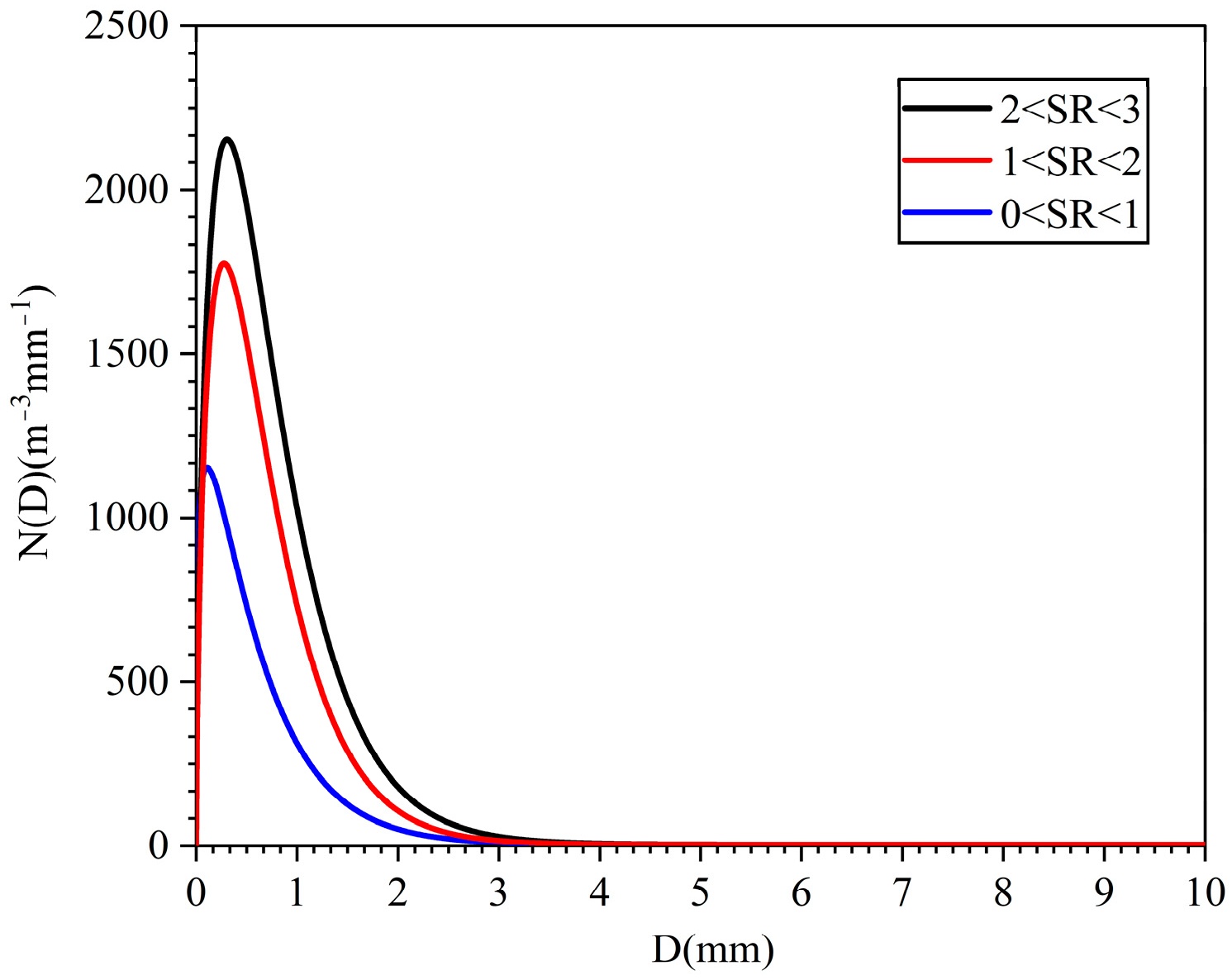
Ranting Tao et al. [14] obtained the PSD curves of snow in the range of three snowfall rates (SRs) (mm/h) by using data measured by a 2-DVD and fitted the PSD curves to obtain the snow particle size distribution model, as shown in Figure 1:
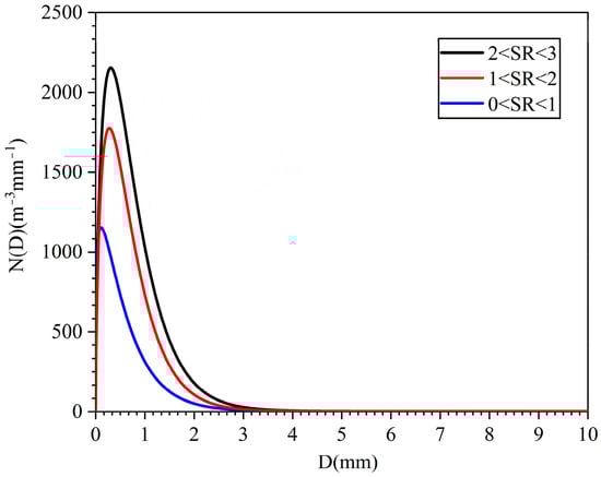
Figure 1.
Snow particle size distribution.
There is good agreement between the model and the measured snow particle size distribution, which is suitable for describing snow particle size distribution in the environment of the Nanjing area; this will be used as a basis to establish a laser transmission attenuation model in snowfall.
3. Transmission Attenuation Model
Studies have shown that the average ratio of the maximum size of the snowflake to its height is close to 1, and thus snowflakes can be considered to be spherical [15]. According to the Mie scattering theory, the attenuation coefficient is wavelength-independent when the size of the scattering particles is much larger than the wavelength of the incident light, which is the case for snow particle scattering, and when the particle size is large relative to the wavelength, Mie scattering can be approximated as Fraunhofer diffraction. However, since the Fraunhofer diffraction theory cannot describe the effect of the refractive index of particles on the scattering field of particles [16], this paper establishes a transmission attenuation model for laser light in snowfall environments based on the Fraunhofer diffraction and ray scattering theories.
3.1. Fraunhofer Diffraction of Snow
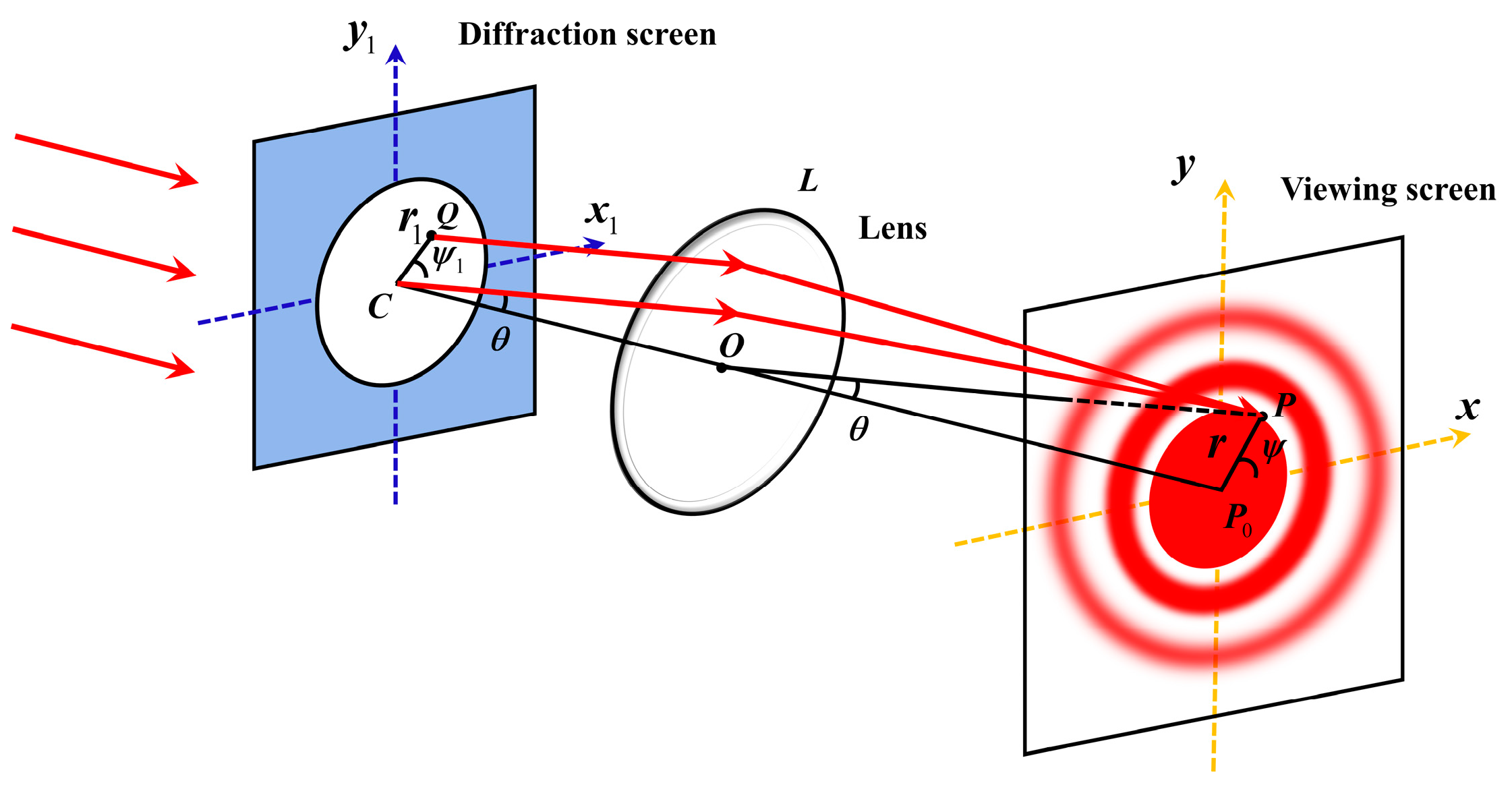
Figure 2 shows the Fraunhofer diffraction schematic. According to the Fresnel–Kirchhoff diffraction formula, the amplitude of light diffracted by a circular hole at any point P can be obtained as [17]:

Figure 2.
Schematic diagram of Fraunhofer diffraction.
Then the diffraction intensity of the circular hole is:
where is the incident light intensity, is the size parameter, , and is the first-order Bessel function.
Therefore, the Fraunhofer diffraction differential scattering attenuation cross-section for snow particles is:
Integrate Equation (6) to obtain the Fraunhofer diffraction decay cross-section for snow particles:
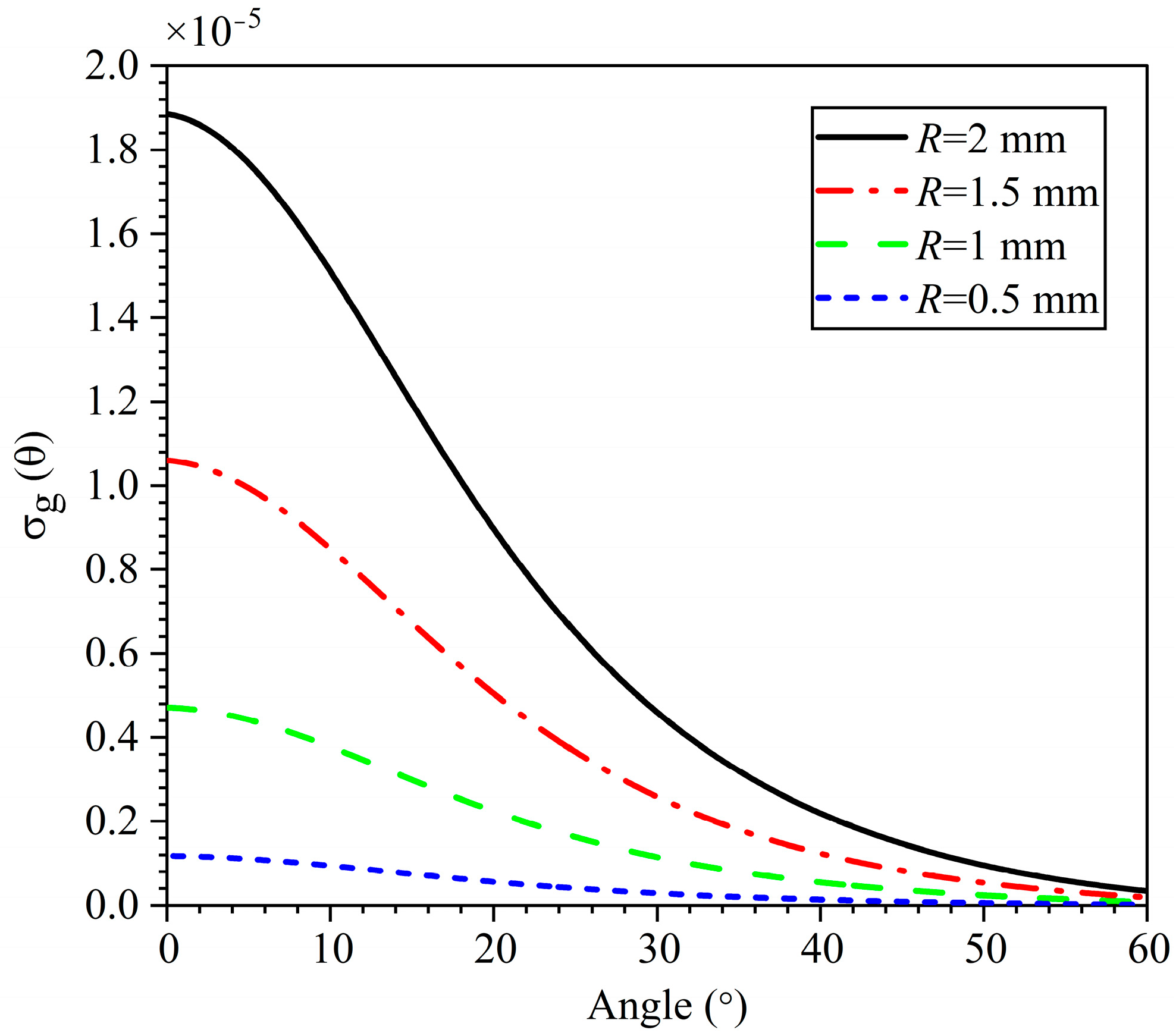
Figure 3 shows the distribution of the Fraunhofer diffraction differential scattering attenuation cross-section when the wavelength of the laser beam is 905 nm and the radius of the snow particles is R = 0.5 mm, 1 mm, 1.5 mm, or 2 mm.
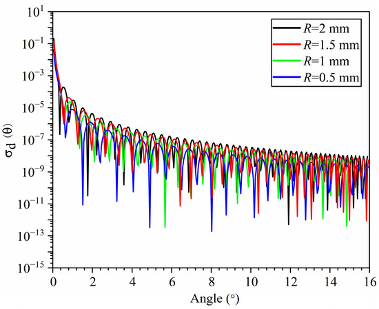
Figure 3.
Fraunhofer diffraction differential scattering attenuation cross-section distribution.
3.2. Ray Scattering of Snow
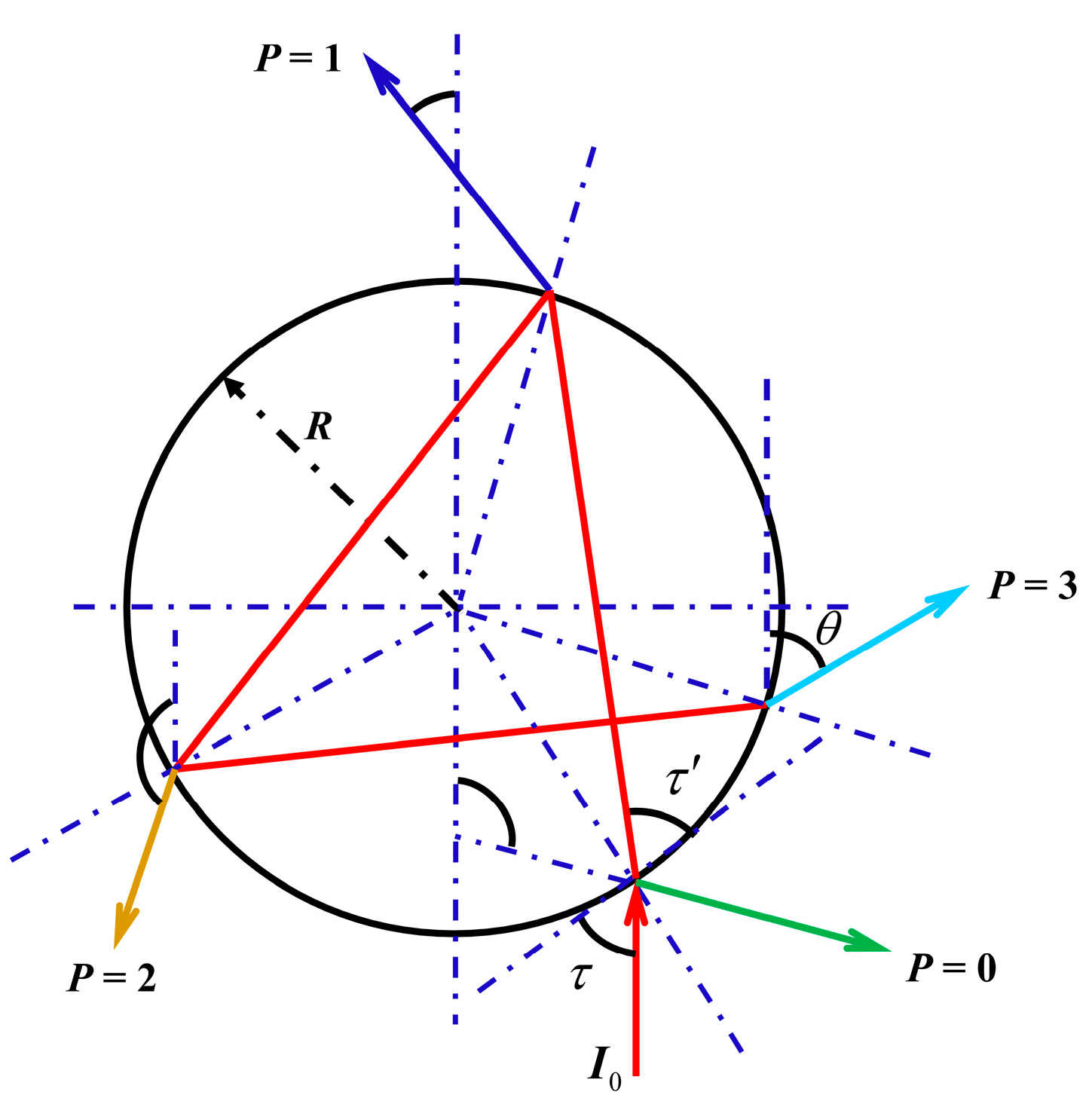
As shown in Figure 4, refraction and reflection will occur when the light of intensity is incident on a spherical particle of radius R. P denotes the number of interactions of the light with the inner surface of the spherical particle. Then, the intensity of the outgoing beam when the distance from the center of the spherical particle is r is [18]:
where is the dimensionless scattering intensity, is the divergence, is the size parameter, and is the energy ratio of the vertical polarization component (j = 1) or the parallel polarization component (j = 2) to the incident beam.
where and .

Figure 4.
Schematic diagram of light propagation.
For forward scattering of uniform particles, only the contributions of P = 0 and P = 1 rays need to be considered. Then, the light intensity of snow particle ray scattering is:
Therefore, the differential scattering decay cross-section for snow particle ray scattering is:
Integrate Equation (11) to obtain the snow particle ray scattering attenuation cross-section:
Figure 5 shows the distribution of differential scattering attenuation cross-sections for geometrical optical scattering when the wavelength of the laser beam is 905 nm and the radius of the snow particles is R = 0.5 mm, R = 1 mm, R = 1.5 mm, or R = 2 mm.
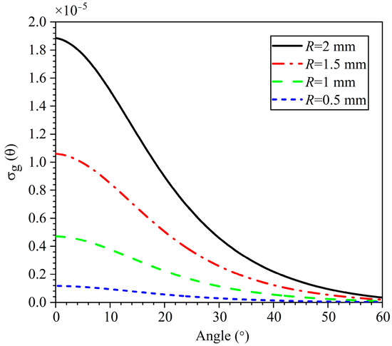
Figure 5.
Distribution of differential scattering attenuation cross-section of ray scattering.
Therefore, the scattering attenuation cross-section of laser light by a single spherical snow particle is:
3.3. Absorption Attenuation Characteristics of Snow Particles
Since the complex refractive index of ice at 905 nm is , there is also absorption attenuation of snow particles at this wavelength of the laser beam, defining the absorption cross-section of snow particles as :
where , and and are the real and imaginary parts of the refractive index of ice, respectively.
The absorption coefficient under snowfall conditions is:
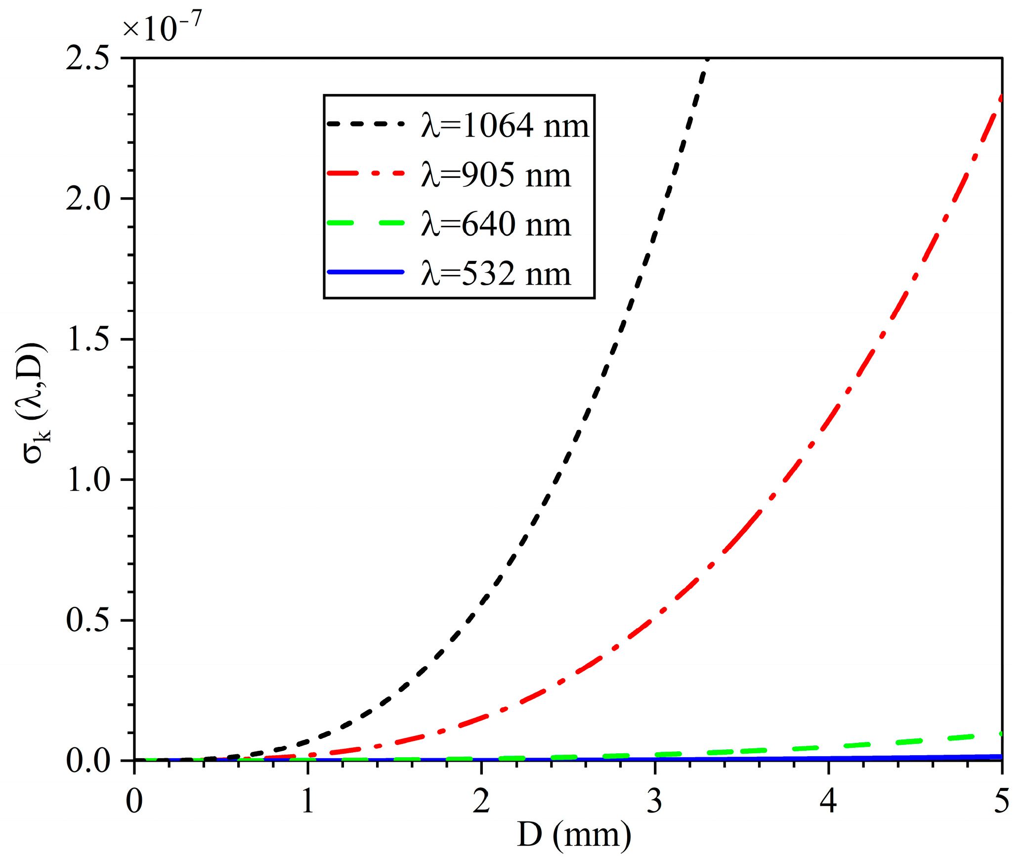
Figure 6 shows the distribution of the absorption cross-sections of snow particles corresponding to different wavelengths. As can be seen from the figure, the absorption of the blue-green wavelength laser by snow particles is significantly lower than that of the near-infrared wavelength.
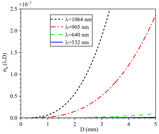
Figure 6.
Cross-sectional distribution of absorption attenuations of snow particles at different wavelengths.
3.4. Transmission Attenuation Model
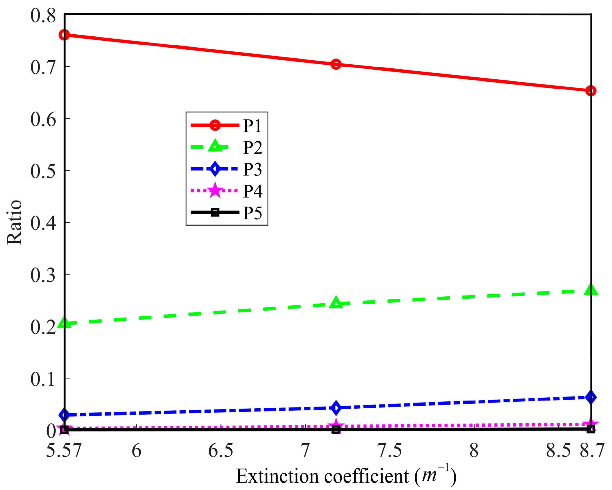
Figure 7 shows the variation curves of the ratio of each scattered photon to the total received photons when the laser transmits 50 m in a snowfall environment simulated by using the Monte Carlo model, and P1–P5 represents the ratios of one to five scattered photons to the total received photons, respectively. As can be seen from the figure, the number of photons undergoing multiple scattering increases with the increase of the extinction coefficient, and the fourth and fifth scattering account for a small proportion of the multiple scattering, so the effect of the first three scatterings needs to be considered in the study of attenuation of laser transmission in snowfall environments. In this paper, the influence of multiple scattering effects on the attenuation process is considered by introducing a forward correction coefficient.

Figure 7.
Variation curve of the ratio of each scattered photon to the total received photons.
Deepak and Vaughan [19] proposed the following forward correction coefficient approximation formula:
Then the corrected scattering coefficient is:
Therefore, the extinction coefficient of snow particles is [20]:
Table 1 shows the absorption coefficients, scattering coefficients, and extinction coefficients of laser light in different SR ranges calculated according to Equations (15), (17), and (18).

Table 1.
Scattering coefficients, absorption coefficients, and extinction coefficients of a 905 nm laser in different SR ranges.
According to the Beer–Lambert law, the transmittance of the laser beam in the snowfall environment is:
where is the transmittance, is the extinction coefficient, and L is the transmission distance.
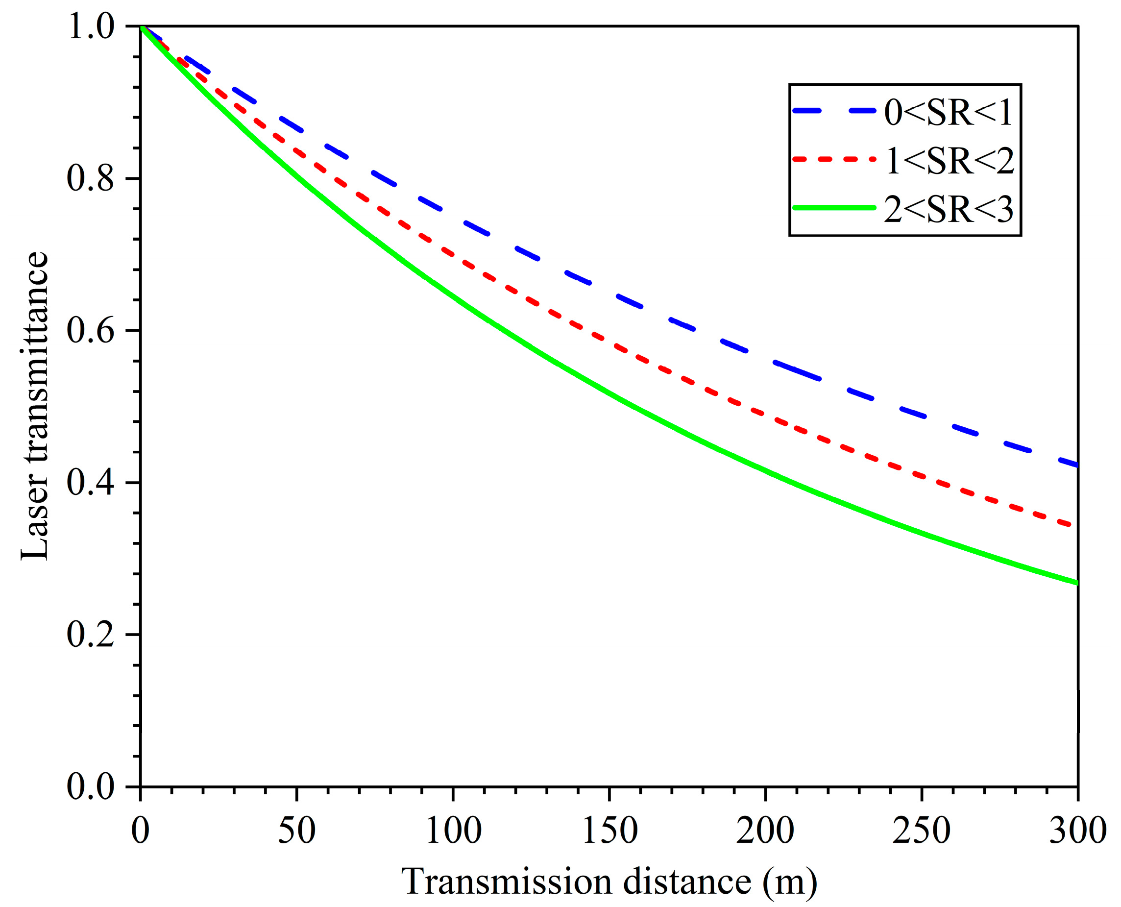
Figure 8 shows the relationship between laser transmittance and transmission distance in different SR ranges. From the figure, it can be seen that, when SR is certain, the transmittance decreases with the increase in transmission distance; when the transmission distance is certain, the transmittance decreases with the increase in SR. Therefore, under the requirement of certain laser transmittance, the applicable detection distance of the laser detection system in a snowfall environment with different SR is different.
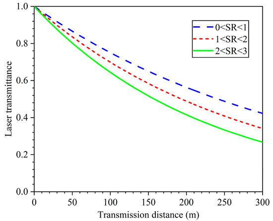
Figure 8.
Plot of laser transmittance versus transmission distance.
4. Monte Carlo Multiple Scattering Model
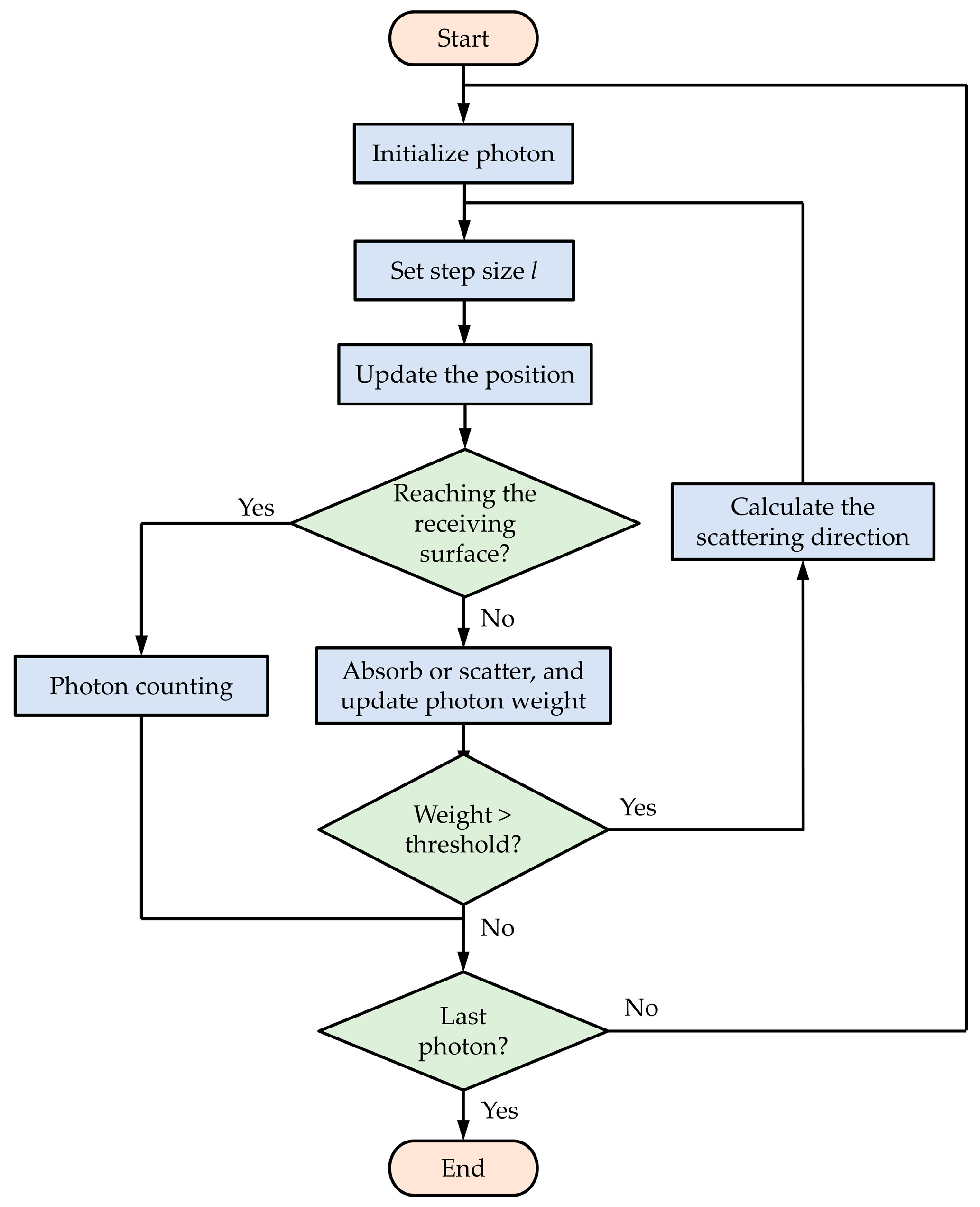
In this paper, the Monte Carlo method was used to study the influence of snowfall on the power attenuation characteristics and spot expansion characteristics of laser beams. Figure 9 indicates the basic flowchart for photon tracing using the Monte Carlo method, as follows. Assuming that the receiving surface is infinite and centered on the z-axis, the emitting light source is a collimated laser beam, the initial weight of the photon is , the initial position is , and the initial direction of motion is , the random step of the photon between two neighboring collisions is [21,22]:
where is a random number between (0,1) and is the extinction coefficient.

Figure 9.
Flowchart of the Monte Carlo simulation process.
The position after the photon row advances l is determined by the current position and the transmission direction :
At the same time, after the photon moves one step, some of the energy is absorbed by the snow particles, and the weight is reduced to [23]:
After the photon collision, its azimuthal angle obeys a uniform distribution on , and the scattering angle is obtained by sampling the H-G scattering phase function [24]. The sampling values of the two are:
where g is the asymmetry factor.
Then the new transmission direction in the global coordinate system after the photon collision is [25]:
If , then there is:
If the weight of the photon is below the threshold ( in this paper), the photon is considered to die out and is no longer tracked; if the weight is above the threshold, the photon continues to migrate randomly until it dies out or is picked up by the detector. After the photon is terminated, the next photon is simulated until all photons are completed.
4.1. Power Attenuation Characteristics Analysis
Assuming that the transmission distance is 0~300 m under the three snowfall conditions of 0 < SR < 1, 1 < SR < 2, and 2 < SR < 3, receiving surfaces are set up with a spacing of 5 m in the transmission direction, and the total number of photons arriving at the center of the receiving surface is counted as , where represents three snowfall conditions, and represents different positions of the receiving surface. Then, the transmittance of the laser at a transmission distance of n for the mth snowfall case is:
where N is the initial photon number (N = 30,000 in this simulation).
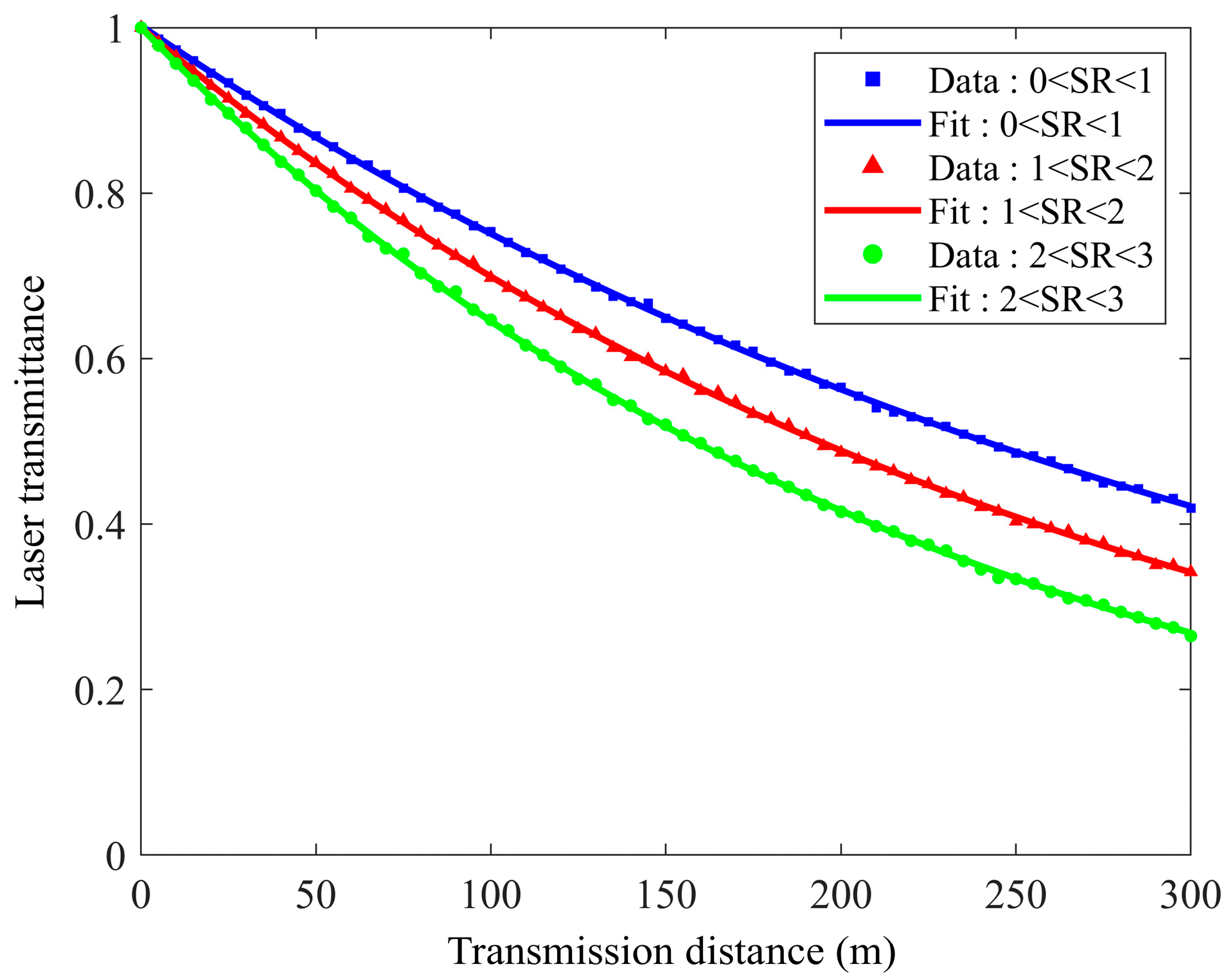
Figure 10 shows the relationship between laser transmittance and transmission distance obtained by the Monte Carlo multiple scattering model. The three colored scatters in the figure represent the three snowfall conditions, and the three smooth curves are the single exponential curves obtained by fitting the three sets of scatter plots. From the simulation results, it can be seen that the laser transmittance decreases with the increase in transmission distance in all three snowfall cases, and when the transmission distance is certain, the laser transmittance decreases with the increase in SR, which is consistent with the change curves obtained from the theoretical calculations in the previous section.
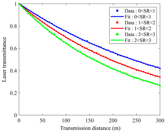
Figure 10.
Simulated plot of laser transmittance versus propagation distance.
4.2. Spot Expansion Characteristics Analysis
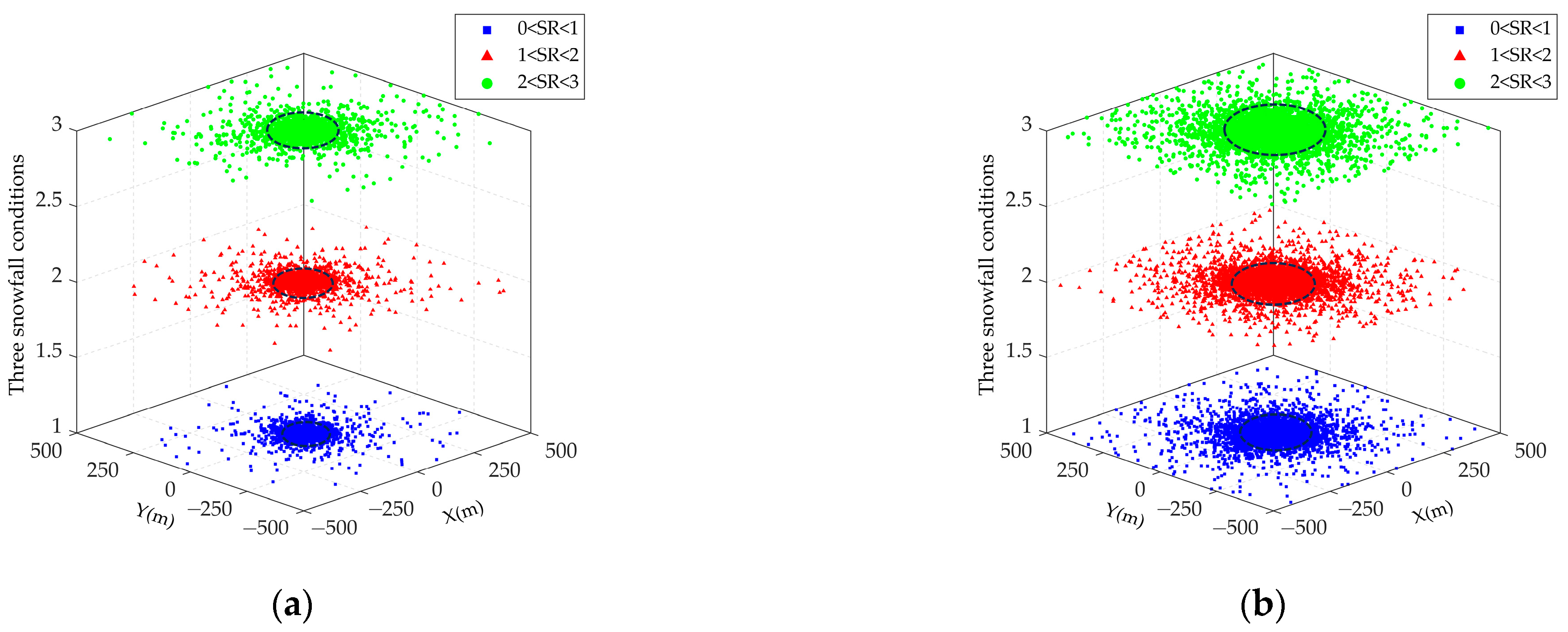
Because the laser beam will be scattered by snow particles when passing through the snowfall medium, the scattering effect changes the direction of motion of some photons and causes the spot to expand. The effect of snowfall on laser beam spot extension can be obtained by counting the number of photons arriving at the receiver and obtaining the distribution of their positions on the receiving surface. The spot radius is defined as the radius that contains 76% of the beam energy, represented by the black dotted circle in the simulation. The influence of transmission distance, simulated photon number, and asymmetry factor on spot expansion is analyzed below.
Assuming the simulated photon number is N = 30,000 and the asymmetry factor is g = 0.9, the influence of the transmission distance on the spot expansion is obtained. It can be seen from Figure 11 that the spot radius increases with the increase of transmission distance under the three snowfall conditions. The simulations show that, when the transmission distance 100 m, 200 m, 300 m, and 400 m, the spot radius is 7.02 m, 33.1 m, 76.1 m, and 128.2 m for snowfall 0 < SR < 1, respectively; the spot radius is 10.1 m, 42.6 m, 93.05 m, and 161.6 m for snowfall 1 < SR < 2, respectively; and the spot radius is 12.6 m, 52.3 m, 111.2 m, and 187.8 m for snowfall 2 < SR < 3, respectively. This is because, as the transmission distance increases, the number of photons scattered during transmission increases, and the distance from the random position of the photon to the center of the receiver becomes larger, resulting in expansion of the spot.
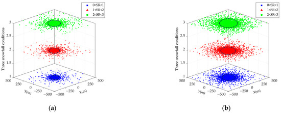
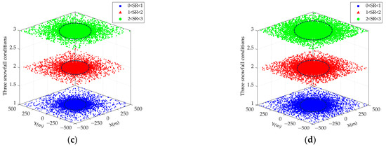
Figure 11.
Effect of transmission distance on spot expansion: (a) L = 100 m; (b) L = 200 m; (c) L = 300 m; and (d) L = 400 m.
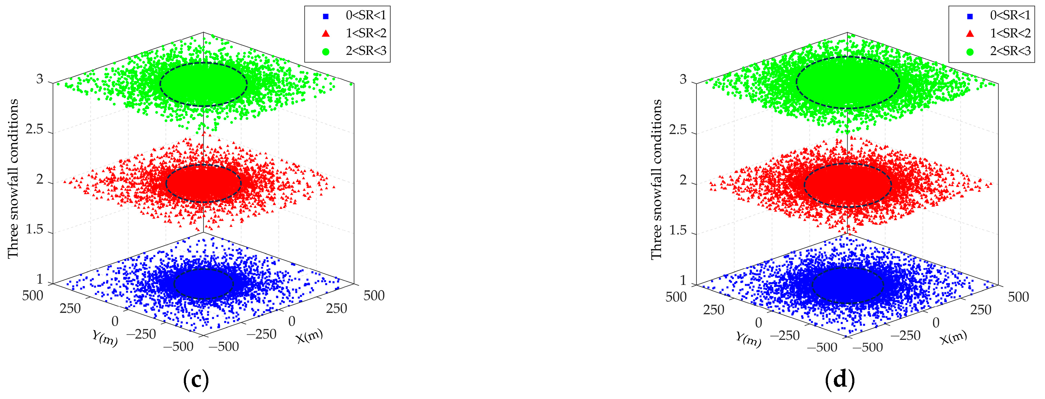
Assuming a transmission distance of L = 400 m and an asymmetry factor of g = 0.9, the influence of the simulated photon number on the spot expansion is obtained. It can be seen from Figure 12 that the photon number distribution is highest near the center of the receiving surface, and the spot radius remains almost constant with the increase in the simulated photon number under the three snowfall conditions. The simulations show that, when the simulated photon number is 5000, 10,000, 20,000, and 40,000, the spot radius is 123.2 m, 130.4 m, 130.98 m, and 131.4 m for snowfall 0 < SR < 1, respectively; the spot radius is 162.4 m, 163.3 m, 163.8 m, and 163.3 m for snowfall 1 < SR < 2, respectively; and the spot radius is 193.7 m, 196.3 m, 196.3 m, and 196.3 m for snowfall 2 < SR < 3, respectively. According to the statistical calculation of the model, when 0 < SR < 1, the probability of photons falling at the center of the receiving surface with different N values is 32.12% (N = 5000), 31.97% (N = 10,000), 31.72% (N = 20,000), and 31.53% (N = 40,000), respectively. Statistical calculations show that the increase in the number of photons does not significantly affect the energy attenuation of photons.
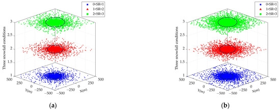
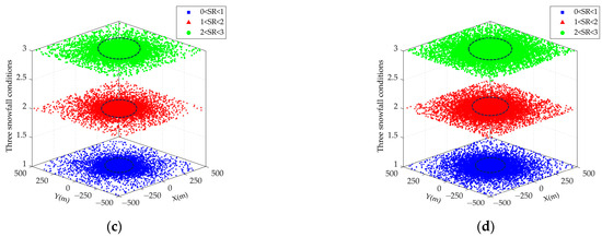
Figure 12.
Effect of the simulated photon number on spot expansion: (a) N = 5000; (b) N = 10,000; (c) N = 20,000; and (d) N = 40,000.
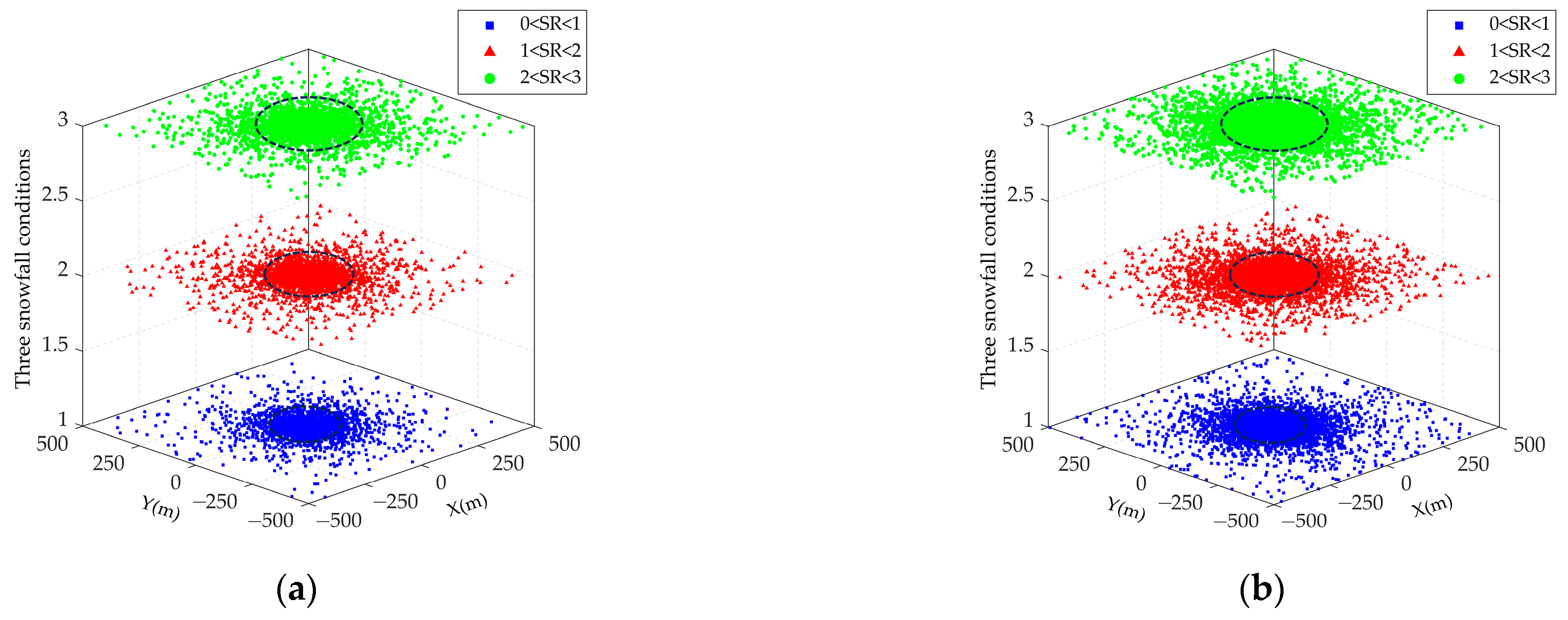
Assuming a transmission distance of L = 300 m and a simulated photon number of N = 30,000, the influence of the asymmetry factor on the spot extension is obtained. It can be seen from Figure 13 that the spot radius decreases with the increase in the asymmetry factor under the three snowfall conditions. The simulations show that, when the asymmetry factor is 0.8, 0.85, 0.90, and 0.95, the spot radius is 130.7 m, 105.2 m, 75.2 m, and 40.7 m for snowfall 0 < SR < 1, respectively; the spot radius is 163.2 m, 131.9 m, 93.3 m, and 52.1 m for snowfall 1 < SR < 2, respectively; and the spot radius is 190.2 m, 153.1 m, 111.2 m, and 63.5 m for snowfall 2 < SR < 3, respectively. This is because, as the asymmetry factor increases, the forward scattering effect of the laser beam becomes more pronounced; thus, the closer the distance between the random scattering position of the photon and the center of the receiver, the smaller the spot radius.
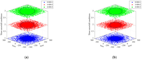

Figure 13.
Effect of the asymmetry factor on spot expansion: (a) g = 0.8; (b) g = 0.85; (c) g = 0.9; and (d) g = 0.95.
5. Experimental Verification
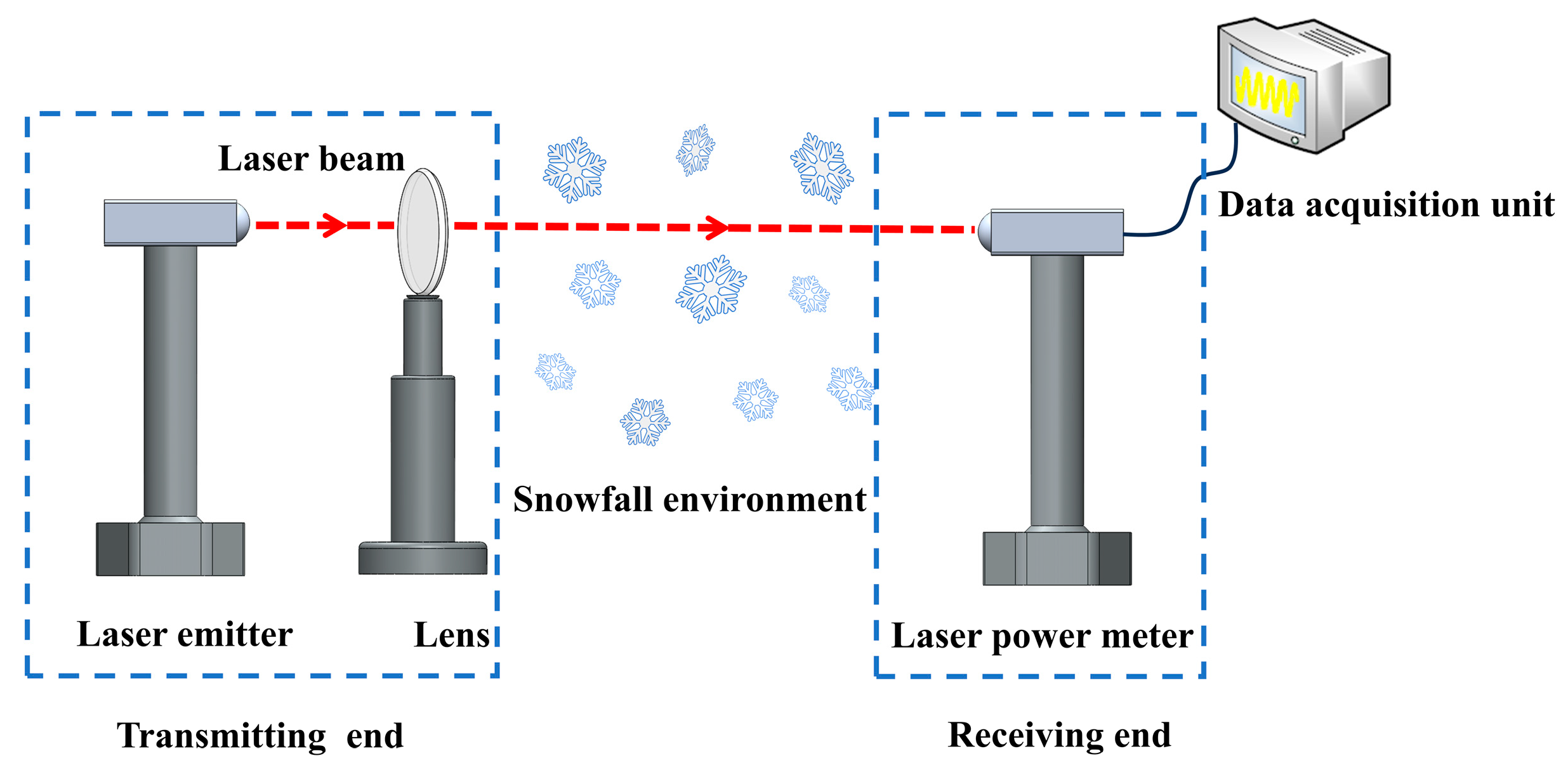
Laser transmission in a snowfall environment is subject to scattering and absorption by snow particles, resulting in laser energy attenuation at the receiving end. In order to verify the correctness of the theoretical attenuation model, an outdoor measurement device for laser transmission attenuation in snowfall environments was built according to the Beer–Lambert law, as shown in Figure 14. The experimental principle: the laser at the transmitting end emits a laser beam at a given power, and the collimated laser beam is transmitted in a snowfall environment. The attenuated laser signal is converged to the detection surface of the optical power meter, and the laser power meter is connected to the data acquisition device through a USB converter line. The data acquisition device stores the attenuated laser power in real-time to ensure the completeness of the experimental data and post-processing of the data.
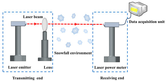
Figure 14.
Diagram of the experimental system.
Following the experimental principles to build the outdoor experimental platform shown in Figure 15a, an FU905AD100-GD1670 laser was selected, and the output wavelength was set to 905 nm. Three snowfall scenarios of 0 < SR < 1, 1 < SR < 2, and 2 < SR < 3 occurred on 18 December 2023 at 7:00, 11:00, and 14:00, respectively. To accurately measure the relationship between laser transmittance and transmission distance in the snowfall environment, the three snowfall experiments were carried out by adjusting the position of the transmitting end to set the transmission distance from 10 m to 100 m in steps of 10 m for 10 experiments, as shown in Figure 15b. To reduce experimental error caused by uncontrollable factors, 15 measurement experiments were performed that corresponded to each receiving surface position. The average value of the 15 measurements was taken as the experimental value.
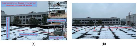
Figure 15.
Experimental scene diagram: (a) experimental scene diagram of pulsed laser transmission in snowfall medium; and (b) experimental scene diagram corresponding to different transmission distances.
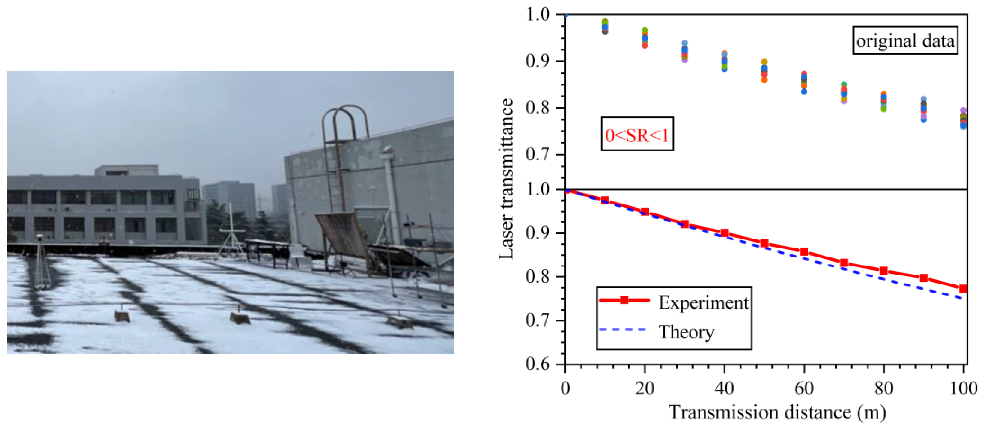
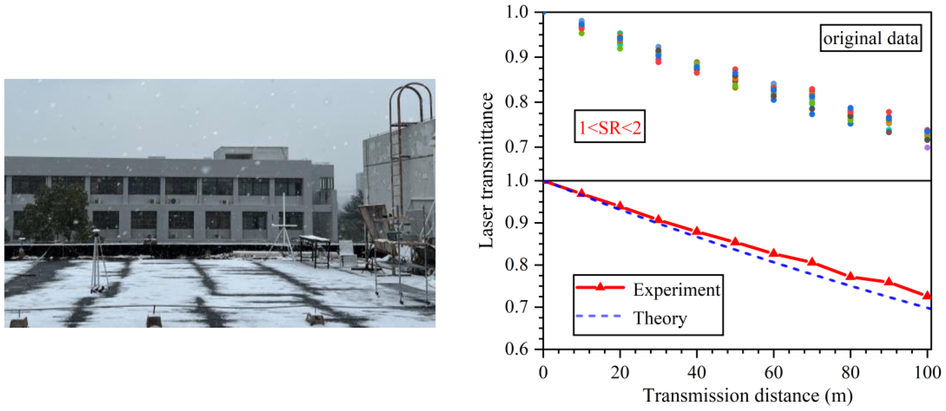
Figure 16, Figure 17 and Figure 18 show the laser transmittance versus transmission distance for laser transmission in three snowfall conditions obtained from theoretical calculations and experimental measurements, with solid circles of different colors representing the original data from 15 experiments. As can be seen from the figures, the experimental results are basically consistent with the theoretical results: both show that the laser transmittance decreases with the increase in transmission distance, and the laser transmittance decreases with the increase in snowfall rate when the transmission distance is the same, which verifies the correctness of the theoretical attenuation model.

Figure 16.
Experimental scene and results for 0 < SR < 1.
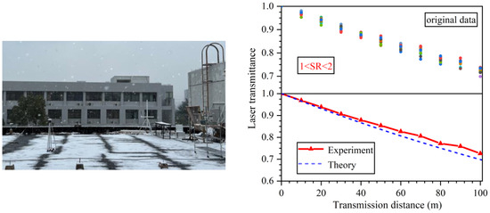
Figure 17.
Experimental scene and results for 1 < SR < 2.
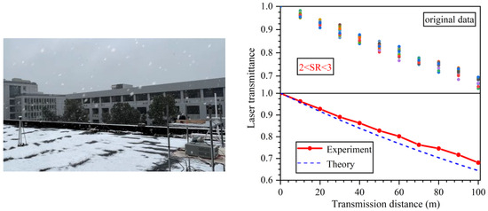
Figure 18.
Experimental scene and results for 2 < SR < 3.
For a more detailed error analysis of the experimental results, the relative error between the experimental and theoretical values was defined using the theoretical values as the true values, as shown in the following equation:
where is the theoretical value and is the experimental value.
From Table 2, it can be seen that, in the case of 0 < SR < 1, the difference between the experimental results and the theoretical results is small. Especially when the transmission distance is short, the two results are basically the same, and only when the transmission distance is greater than 40 m was there a small relative error. As can be seen from Table 3 and Table 4, the difference between the experimental and theoretical results increased in the two cases of 1 < SR < 2 and 2 < SR < 3, and the relative error increased with the increase of transmission distance. The reason for the error is that, in the cases of 1 < SR < 2 and 2 < SR < 3, the laser single scattering rate is larger, the multiple scattering effect is more obvious, and the scattering angle of some photons after multiple scattering is greater than 1.5 degrees, which makes the power received by the optical power meter in the experiment larger than the theoretical calculation. With the increase in transmission distance, the amount of laser scattering increases, so the relative error increases with the increase in transmission distance.
Table 2.
Relative error of laser transmittance for 0 < SR < 1.
Table 3.
Relative error of laser transmittance for 1 < SR < 2.
Table 4.
Relative error of laser transmittance for 2 < SR < 3.
In addition, due to the limitation of snowfall time, only 15 measurement experiments were carried out for each receiving surface position under the three snowfall environments. The small number of experiments increases experimental measurement error, which could make the experimental results deviate from the theoretical values. The measurement experiments were carried out outdoors at Nanjing University of Science and Technology (NUST), and there are many uncontrollable factors in the measurement environment, such as air quality changes and temperature changes. These uncontrollable factors increase the scattering sources in the measurement environment, which led to the experimental value of laser transmittance being larger than the theoretical value.
6. Conclusions
In this paper, for the phenomena of laser power attenuation and spot expansion at the receiving end when a laser is transmitted in snowfall environments due to the scattering and absorption of snow particles, a transmission attenuation model of a 905 nm pulsed laser in snowfall environments was established based on the ray scattering and Fraunhofer diffraction theories. The Monte Carlo multiple scattering model was used to numerically simulate the power attenuation characteristics of a 905 nm pulsed laser in snowfall environments, and an outdoor experimental platform of pulsed laser transmission characteristics in a snowfall environment was constructed by combining the Beer–Lambert law. Theoretical, simulation, and experimental results show that (1) the laser transmittance decreases with the increase in the transmission distance for all three snowfall environments; and (2) when the transmission distance is the same, the laser transmittance decreases with the increase in the snowfall rate.
The influence of transmission distance, simulated photon number, and asymmetry factor on laser beam spot expansion were analyzed by the Monte Carlo multiple scattering model. The simulation results show that, in three snowfall conditions, (1) the spot radius increases with the increase in transmission distance; (2) the spot radius remains almost constant with the increase in the simulated photon number; and (3) the spot radius decreases with the increase in the asymmetry factor. This paper addresses the study of the transmission attenuation characteristics of pulsed laser light by snowfall, which is of great theoretical and guiding value for the accurate measurement of laser detection systems in snowfall environments.
Since this paper focuses on the attenuation characteristics of a pulsed laser during short-range transmission in snowfall environments, the theoretical attenuation model based on ray scattering and Fraunhofer diffraction theories was constructed by superposing the intensity of light rays at the same scattering angle without considering the effect of the laser on the particle-scattering field due to the change of the phase during the transmission process. Therefore, if this model is applied to the long-distance transmission of pulsed laser light, the complex amplitude function of the light wave incident on the particle after reflection, refraction, and diffraction should be calculated based on the ray scattering and Fraunhofer diffraction theories. Then, the scattering complex amplitude function and the diffraction complex amplitude function at the same scattering angle are superimposed to obtain the scattering field of the particle, and then the light scattering characteristics of the particle are investigated.
In addition, since the research environment of this paper is snowfall environments, and the scattering of the pulsed laser by snow particles is mainly forward scattering, only reflections and refractions with P = 1 were considered in the calculation of ray scattering in this paper. Therefore, if this model is applied to calculate scattered intensity distribution in the omnidirectional angular range, it is necessary to consider the influence of higher-order scattered rays with P ≥ 2 on the particle scattering field.
Author Contributions
Conceptualization, L.G.; data curation, L.G. and M.C.; formal analysis, M.C.; investigation, L.G. and M.C.; methodology, M.C.; project administration, L.G. and H.Z.; resources, L.G. and H.Z.; software, M.C. and C.K.; supervision, L.G.; validation, M.C. and C.K.; visualization, M.C.; writing—original draft, M.C.; writing—review & editing, L.G. and M.C. All authors have read and agreed to the published version of the manuscript.
Funding
This research was funded by the National Natural Science Foundation of China, grant number 51605227.
Institutional Review Board Statement
Not applicable.
Informed Consent Statement
Not applicable.
Data Availability Statement
Data are contained within the article.
Conflicts of Interest
The authors declare no conflicts of interest.
References
- Gao, L.; Chen, H.; Chen, G.; Deng, J. Particle Size Distributions and Extinction Coefficients of Aerosol Particles in Land Battlefield Environments. Remote Sens. 2023, 15, 5038. [Google Scholar] [CrossRef]
- Khalid, H.; Sajid, S.M.; Cheema, M.I.; Leitgeb, E. Optical Signal Attenuation through Smog in Controlled Laboratory Conditions. Photonics 2024, 11, 172. [Google Scholar] [CrossRef]
- Zheng, S.; Han, C.; Huo, J.; Cai, W.; Zhang, Y.; Li, P.; Zhang, G.; Ji, B.; Zhou, J. Research on Rainfall Monitoring Based on E-Band Millimeter Wave Link in East China. Sensors 2021, 21, 1670. [Google Scholar] [CrossRef] [PubMed]
- Gergely, M.; Transfer, R. Sensitivity of snowfall radar reflectivity to maximum snowflake size and implications for snowfall retrievals. J. Quant. Spectrosc. Radiat. Transf. 2019, 236, 106605. [Google Scholar] [CrossRef]
- Flecker, B.; Gebhart, M.; Leitgeb, E.; Muhammad, S.S.; Chlestil, C. Results of attenuation-measurements for optical wireless channels under dense fog conditions regarding different wavelengths. Proc. SPIE Int. Soc. Opt. Eng. 2006, 6303, 411–415. [Google Scholar] [CrossRef]
- Roy, G.; Cao, X.Y.; Bernier, R.; Tremblay, G. Physical model of snow precipitation interaction with a 3D lidar scanner. Appl. Opt. 2020, 59, 7660–7669. [Google Scholar] [CrossRef]
- Rahm, M.; Jonsson, P.; Henriksson, M. Laser attenuation in falling snow correlated with measurements of snow particle size distribution. Opt. Eng. 2021, 60, 094102. [Google Scholar] [CrossRef]
- Tyynelä, J.; Leinonen, J.; Moisseev, D.; Nousiainen, T. Radar Backscattering from Snowflakes: Comparison of Fractal, Aggregate, and Soft Spheroid Models. J. Atmos. Ocean. Technol. 2011, 28, 1365–1372. [Google Scholar] [CrossRef]
- Nowell, H.; Liu, G.S.; Honeyager, R. Modeling the microwave single-scattering properties of aggregate snowflakes. J. Geophys. Res. Atmos. 2013, 118, 7873–7885. [Google Scholar] [CrossRef]
- Wang, R. Study on Attenuation Characteristics of Laser Propagation in Fog Medium. Master’s Thesis, Xidian University, Xi’an, China, 2007. [Google Scholar]
- Yang, Y.; Qin, J.; Wang, Z. Effect of Martian dust aerosol on laser transmission characteristics. Acta Photonica 2018, 47, 221–226. [Google Scholar] [CrossRef]
- Gunn, K.; Marshall, J. The distribution with size of aggregate snowflakes. J. Atmos. Sci. 1958, 15, 452–461. [Google Scholar] [CrossRef]
- Sekhon, R.; Srivastava, R. Snow size spectra and radar reflectivity. J. Atmos. Sci. 1970, 27, 299–307. [Google Scholar] [CrossRef]
- Tao, R.T.; Zhao, K.; Huang, H.; Wen, L.; Zhang, G.F.; Zhou, A.; Chen, H.N. Snow Particle Size Distribution From a 2-D Video Disdrometer and Radar Snowfall Estimation in East China. IEEE Trans. Geosci. Remote Sens. 2021, 59, 196–207. [Google Scholar] [CrossRef]
- Geng, Y.Y.; Ma, Y.K.; Zhang, J.S. Analytical study on the effect of rain and snow on LiDAR performance. Electron. Des. Eng. 2022, 30, 97–102. [Google Scholar] [CrossRef]
- Xu, R. Light scattering: A review of particle characterization applications. Particuology 2015, 18, 11–21. [Google Scholar] [CrossRef]
- Zhao, K. New Concept Physics Course Optics; Higher Education Press: Beijing, China, 2004. [Google Scholar]
- Li, X. Geometrical-Optics Approximation of Light Scattering by Particles. Ph.D. Thesis, Xidian University, Xi’an, China, 2009. [Google Scholar]
- Deepak, A.; Vaughan, O.H. Extinction-sedimentation inversion technique for measuring size distribution of artificial fogs. Appl. Opt. 1978, 17, 374–378. [Google Scholar] [CrossRef]
- Zhang, L.; Tang, X.; Sun, C.; Chen, Z.; Li, Z.; Wang, H.; Jiang, R.; Shi, W.; Zhang, A. Over 10 attenuation length gigabits per second underwater wireless optical communication using a silicon photomultiplier (SiPM) based receiver. Opt. Express 2020, 28, 24968–24980. [Google Scholar] [CrossRef]
- Hu, S.; Liu, H.; Zhao, L.; Bian, X. The Link Attenuation Model Based on Monte Carlo Simulation for Laser Transmission in Fog Channel. IEEE Photonics J. 2020, 12, 1–10. [Google Scholar] [CrossRef]
- Yang, B.; Yu, H.; Liu, C.F.; Wei, X.; Fan, Z.C.; Miao, J. An Aero-Optical Effect Analysis Method in Hypersonic Turbulence Based on Photon Monte Carlo Simulation. Photonics 2023, 10, 172. [Google Scholar] [CrossRef]
- Jasman, F.; Zaiton, A.; Ahmad, Z.; Rihawi, Z. Scattering Regimes for Underwater Optical Wireless Communications using Monte Carlo Simulation. Int. J. Electr. Comput. Eng. IJECE 2018, 8, 2571–2577. [Google Scholar] [CrossRef]
- Li, C.Y.; Zhou, G.Q.; Zhang, D.J. Analysis of affecting factors for laser underwater transmission echo signals based on semi-analytic Monte Carlo. Int. J. Remote Sens. 2023, 1–27. [Google Scholar] [CrossRef]
- He, Y.T.; Liu, Y.J.; Liu, C.; Li, D. Analysis of Transmission Depth and Photon Number in Monte Carlo Simulation for Underwater Laser Transmission. Remote Sens. 2022, 14, 2565. [Google Scholar] [CrossRef]


Disclaimer/Publisher’s Note: The statements, opinions and data contained in all publications are solely those of the individual author(s) and contributor(s) and not of MDPI and/or the editor(s). MDPI and/or the editor(s) disclaim responsibility for any injury to people or property resulting from any ideas, methods, instructions or products referred to in the content. |
© 2024 by the authors. Licensee MDPI, Basel, Switzerland. This article is an open access article distributed under the terms and conditions of the Creative Commons Attribution (CC BY) license (https://creativecommons.org/licenses/by/4.0/).