Article

Rapid Focused Spot Scanning Imaging Using Multimode Fiber with a Convolutional Neural Network-Based Phase Modulation

1
MIIT Key Laboratory of Advanced Solid Laser, Nanjing University of Science and Technology, Nanjing 210094, China
2
School of Electronic and Optical Engineering, Nanjing University of Science and Technology, Nanjing 210094, China
*
Author to whom correspondence should be addressed.
Photonics 2025, 12(1), 41; https://doi.org/10.3390/photonics12010041
Submission received: 1 December 2024 / Revised: 28 December 2024 / Accepted: 3 January 2025 / Published: 5 January 2025

Abstract

:
In this paper, we present a rapid beam-focusing method for multimode fiber (MMF) that integrates a Convolutional Neural Network (CNN) with a Spatial Light Modulator (SLM). This approach efficiently focuses light fields by training neural networks to approximate the transmission matrix of the optical system, eliminating the need for iterative calculations. Experimental results indicate that this method can generate focused spots within 200 ms, representing a significant improvement over traditional methods. Additionally, the feasibility of point-scanning imaging was verified using the USAF-1951 test target with a resolution greater than 7.81 μm. This advance is expected to improve the speed and accuracy of endoscopic imaging and other real-time imaging applications, potentially leading to more effective diagnostic tools and imaging technologies in medical and industrial settings.

1. Introduction

Multimode fiber (MMF) is widely used across applications such as biomedical imaging [1,2], optical communication [3], quantum information transmission [4], and optical sensing [5] due to its high signal throughput, flexibility, and compact size. In particular, MMF plays a crucial role in endoscopic imaging for clinical diagnosis [6,7,8], where its flexibility allows for navigation through complex and narrow anatomical pathways, enabling real-time high-resolution imaging. These advantages make MMF highly suitable for minimally invasive diagnostics and surgeries. However, variations in group velocities among different propagation modes in MMF result in modal interference and coupling during light transmission, generating a random speckle pattern in the output optical field. This phenomenon significantly disrupts the reliable transmission of the phase and amplitude information in the optical field [9,10,11], limiting the ability of fiber-based imaging systems to accurately represent an object’s structure and details. Addressing these distortions to recover object information and achieve rapid high-quality imaging using MMF is a critical technical challenge in this domain [12,13].
Various strategies have been explored to improve the reconstruction accuracy and real-time performance of MMF imaging systems. The Transmission Matrix (TM) method [14,15,16], a classical optical field modeling approach, effectively characterizes the input–output relationships of the optical field, providing insights into mode propagation within MMF. However, its practical application is hindered by laborious experimental measurements and complex calibration requirements. The Digital Phase Conjugation (DPC) method [17,18,19] achieves wavefront correction by conjugating the optical field. Although it can restore image quality, the method relies on high-precision equipment and complex phase-retrieval processes, resulting in significant computational overhead. Wavefront shaping techniques employing feedback mechanisms [20,21], iteratively adjust the wavefront using algorithms such as genetic algorithm [22], simulated annealing algorithm [23], Monte-Carlo method [24], adaptive sequential coordinate ascent algorithm [25], and parallel coordinate algorithm [26,27]. While these methods enhance imaging performance, their iterative processes are computationally intensive and time-consuming, making it challenging to meet the requirements for rapid real-time imaging.
Recently, deep learning has emerged as a transformative solution for MMF imaging. Unlike traditional methods requiring time-intensive transmission matrix measurements and intricate calibration, deep learning leverages nonlinear models to approximate the input–output relationships of the fiber directly, circumventing dependence on the system’s physical parameters [28]. Although training neural networks and acquiring data require offline processing time, the trained models facilitate rapid real-time imaging without repeated calibration or measurement [29]. Recent advancements have focused on enhancing the scalability and robustness of deep learning models, particularly in dynamically deformed MMF environments [30,31], without the need to remeasurement of the transmission matrix following changes in the MMF’s state [32]. Furthermore, newer deep learning approaches have shown promising results in the image transmission in multimode fiber systems, while reducing computational cost and complexity using transfer learning [33]. These results further advance the application of deep learning techniques to dynamic and real-time MMF systems.
In this study, we propose a novel beam-focusing technique for MMF systems by leveraging a convolutional neural network (CNN) model. This method establishes mapping between the phase patterns applied to the spatial light modulator (SLM) and the output light field of the MMF. Through training the neural network, the CNN effectively fits the transmission matrix of the optical system, enabling the determination of the compensatory phase required to manipulate the distribution of the MMF optical field. The focused light field achieved through this technique demonstrates a Full Width at Half Maximum (FWHM) of 5.288 μm and a focusing efficiency of 27.56% for a 50 μm diameter MMF. Additionally, we implemented a point-scanning imaging system based on this approach, which delivered resolution values of 9.84 μm and 7.81 μm when tested on the USAF-1951 resolution target. Furthermore, this technique significantly reduces the time required to generate the light field, with a processing time of 200 ms. This technique offers a viable solution for enhancing the speed of point-scanning imaging applications in MMF, potentially broadening its utility in various MMF imaging scenarios.

2. Principle and Model

Incident light in MMF is affected by modal dispersion and mode coupling, leading to multiple scattering events that hinder the direct formation of a focused light field. According to fiber mode coupling theory, incident light can be represented as a linear superposition of multiple orthogonal modes, each corresponding to a unique orthogonal light field. By modulating the phase of the incident light field with an SLM, if the incident light is decomposed into m light fields, the output light field after modulation by the SLM can be expressed as follows:
E S L M , out = m = 1 M E S L M , i n m exp ( i φ S L M , m )
where E S L M , i n m is the m-th light field received by the SLM and φ S L M , m is the phase modulation applied to the m-th light field.
When the SLM and the input face of the MMF are located at the front and back focal planes of a lens, the complex amplitude distribution at the MMF’s input face can be represented as the Fourier transform of the SLM’s output light field distribution:
E f i b e r , i n ( u , v ) = { E S L M , o u t ( u , v ) }
where E f i b e r , i n ( u , v ) denotes the complex amplitude distribution at the MMF’s input face, represents the Fourier transform operation, and E S L M , o u t ( u , v ) is the complex amplitude distribution of the output light field from the SLM. With the MMF’s fixed structure, light wave propagation within the MMF can be described using a transmission matrix:
E f i b e r , o u t = T i E f i b e r , i n ( u , v )
where E f i b e r , o u t is the complex amplitude distribution at the output end of the MMF, and T i represents the transmission matrix of the MMF. By combining Equations (1)–(3), we arrive at the following:
E f i b e r , o u t = T i { m = 1 M E S L M , i n m exp ( i φ S L M , m ) }
Once the MMF’s state is determined, its transmission matrix remains stable. Similarly, when the lens position is fixed, the Fourier transform interaction on the SLM’s output light field also stabilizes. With fixed incident light waves, the final received light field distribution is governed by the Fourier transform of the SLM’s complex amplitude. Phase modulation on the SLM enables precise control of light waves entering the MMF, allowing for the output light field to overcome modal dispersion and mode coupling, thus achieving focused spots at specific locations.

3. Simulation and Results

Although the MMF transmission matrix is stable, accurately determining it often requires extensive calibration and repeated measurements, demanding high stability from the experimental setup. Furthermore, calculating the transmission matrix is computationally intensive and time-consuming, creating challenges in producing the output-focused light field efficiently. To address these issues, this study introduces a CNN model to establish the mapping between the phase loaded onto the SLM and the MMF’s output light field, as shown in Figure 1. In this method, the output light field of MMF E f i b e r , o u t serves as the input data to the CNN, while the phase loaded onto the SLM E S L M , i n acts as the output data. The network is continuously trained using a dataset to approximate the MMF’s transmission matrix. During training, the solved E f i b e r , o u t is compared to the actual E f i b e r , o u t , and the CNN parameters are iteratively corrected to minimize the difference between E f i b e r , o u t , and E f i b e r , o u t . This iterative process continues until the error falls within acceptable limits, resulting in a well-trained CNN. Once trained to approximate the optical system’s transmission matrix, the neural network can rapidly calculate the compensatory phase by inputting the corresponding speckle image, bypassing the need for multiple iterations. By applying the compensatory phase to the SLM, the efficient focusing of light fields at arbitrary positions is achieved.
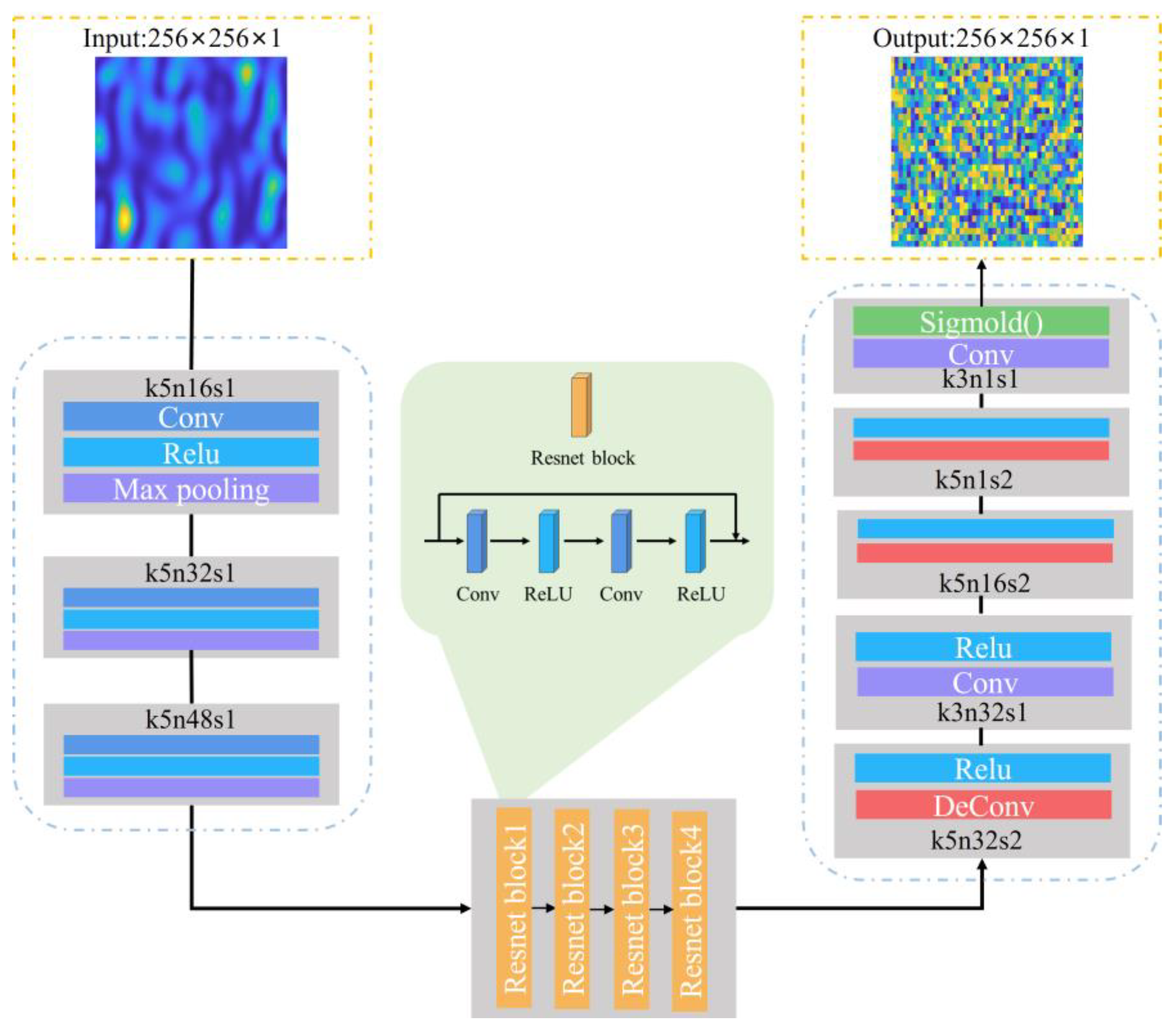
The simulations were conducted using PyTorch 1.10, which provided the necessary libraries and functionalities for designing and training the CNN model. As shown in Figure 2, the CNN model in this study is based on the U-Net architecture and comprises three main components: a convolutional module, residual module, and upsampling module. Hyperparameters were meticulously tuned to optimize performance, including a learning rate of 0.003 and a batch size of 64. The network was trained for 200 epochs, with early stopping implemented to prevent overfitting. These settings were chosen to balance convergence speed and model accuracy, ensuring reproducibility across different datasets. A dataset of 5000 pairs of randomly generated phase values and their corresponding multimode fiber output speckle images was created as training samples. The phase values were uniformly randomized, simulating diverse phase modulation situations. This process ensured a comprehensive coverage of possible light field configurations within the MMF, facilitating the CNN’s ability to accurately predict compensatory phases for new, unseen speckle patterns.
To enhance feature extraction from the input speckle images, the 256 × 256 × 1 speckle images were first passed through a network of convolutional blocks, reducing the image size to 32 × 32 × 1 while increasing the number of channels to 48. The feature maps were then processed through residual blocks to enhance the network’s learning capacity. Following this, the feature maps entered the upsampling module, where a deconvolution operation enlarged the image size to 64 × 64 × 1 and reduced the channel number to 32. Next, the feature maps passed through another convolutional block that maintained both the size and channel count before entering a second upsampling block, which increased the image size to 256 × 256 × 1 and reduced the channel number to 1, improving the detail of the feature maps. This process facilitates comparison with the truth phase and supports the network’s weight updating. Finally, convolution and activation operations were applied to accelerate network convergence, further enhancing solution efficiency.
The selected loss function is Mean Squared Error (MSE), which quantifies the difference between the actual output phase and the predicted compensatory phase. Let R denote the true phase image and P the predicted phase image, both with dimensions M × N, where i and j indicate the rows and columns, respectively. The mathematical expression for the loss function is
M S E = 1 M × N i = 1 M j = 1 N [ ( R ( i , j ) P ( i , j ) ] 2
Following training, the results are shown in Figure 3a. As the number of cycles increases, the MSE quickly converges to approximately 0.001, indicating effective network training. When the test set is input into the trained network, the output yields the compensatory phase for the SLM. The light field generated using this compensatory phase is illustrated in Figure 3b, clearly displaying a focused spot. By examining the intensity distribution at the center of Figure 3b, the intensity distribution curve shown in Figure 3c is obtained, revealing a sharp focusing peak that preliminarily confirms the feasibility and effectiveness of CNN-optimized compensatory phase generation.

4. Experiment Results and Discussion

4.1. The Experiment on Multimode Fiber Beam Focusing

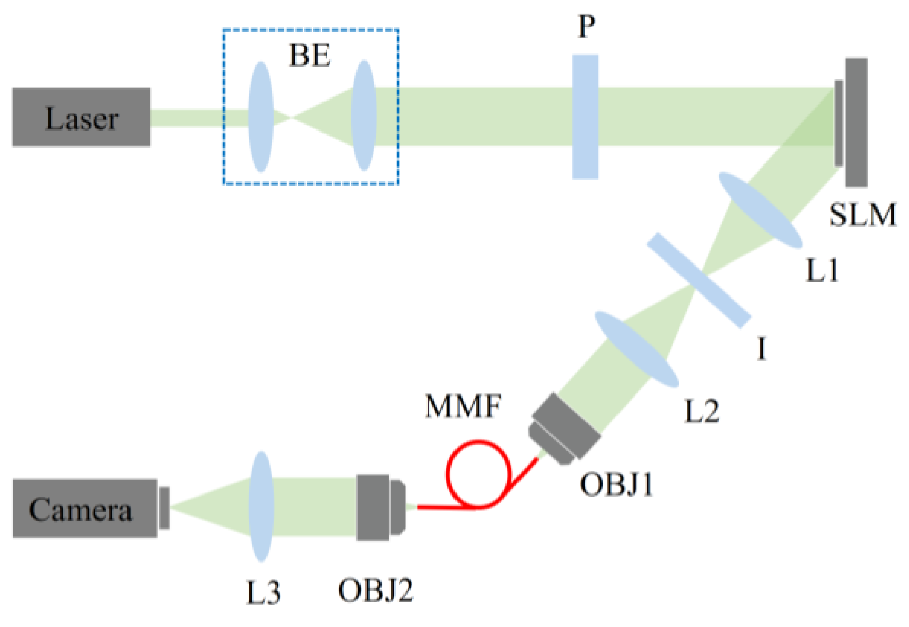
According to the experimental principle, the optical system is constructed as shown in Figure 4. The setup consists of three main components: Illumination: This section includes a 532 nm laser (GL-100-T2, SFOLT Opto-Electronic Technology, Shanghai, China), beam expander (Daheng Optics, Beijing, China), collimating lens (Daheng Optics, Beijing, China), and polarizer (Daheng Optics, Beijing, China). The beam expander and collimating lens create a collimated beam, while the polarizer adjusts the light’s polarization to produce polarized light that meets SLM requirements. Transmission: This section includes the SLM (HDSLM80R Plus, UPOLABS, Shanghai, China, 1920 × 1200 pixels with a pixel size of 8 μm), a 4f system, aperture, microscope objective lens (Daheng Optics, Beijing, China, 4×, numerical aperture (NA) = 0.1), and a 50 μm diameter MMF (Hanyu, Shanghai, China, NA = 0.22). The SLM is divided into multiple subregions, each loading a one-dimensional grating to confine the diffraction order to +1. The aperture selectively allows for only the +1 diffraction light to pass, ensuring purity in the modulated light field. The focusing lens precisely focuses the diffracted beam onto the input face of the MMF, enabling accurate light field coupling. Imaging: This section, composed of a microscope objective lens (Daheng Optics, Beijing, China, 10×, NA = 0.25), a convex lens, and a CCD (MV-CA013-21UM, HIKVISION, Hangzhou, China, 1280 × 1024 pixels with a pixel size of 4.8 μm), magnifies and images the light spots at the MMF output end, allowing for observation of the focused light field characteristics and for evaluating the effects of light field modulation.
In the experiment, the CNN input was the MMF output speckle images collected using a CCD in the optical system, and the output was the corresponding phase distribution loaded onto the SLM. The output light field without CNN optimization is shown in Figure 5a; due to complex modal dispersion and mode coupling within the MMF, the output light field displays a random speckle pattern. Figure 5b shows the optical field after phase modulation by the CNN model. Notably, after optimization of the CNN model, each focused field calculation requires only about 200 ms and does not involve complex iterations. Figure 5c shows the intensity distribution of the corresponding cross-section, clearly illustrating the formation of a focused spot and further verifying the feasibility of the CNN-based multimode fiber focusing method.
To assess the quality of the focused spot, two metrics were employed for quantitative analysis: focusing efficiency and FWHM. Focusing efficiency is defined as the ratio of the total intensity within the focused area to the total output intensity from the MMF, providing a measure of how effectively the focused spot is concentrated. On the other hand, FWHM quantifies the width of the light spot at the point where the intensity reaches half of its maximum value, serving as an indicator of the spot’s spatial resolution. The focusing efficiency of the spot shown in Figure 5b was calculated to be 27.56%, with an FWHM value of 5.288 μm. Compared to the simulation results presented in Figure 3, several notable discrepancies were observed in the experimental data. The most prominent difference is the presence of sidelobes in the experimental results, which were not observed in the simulations. Instead, the simulation results primarily exhibited random speckle noise. Furthermore, the focused spot in the experimental appears larger and more dispersed than in the simulation results. The observed discrepancies can be attributed to several factors. First, system assembly errors may have influenced the experimental outcomes, causing deviations from the simulation predictions. Second, the dynamics in the MMF may contribute to unpredictable fluctuations in the light field, as the fiber’s transmission matrix can change during operation due to factors such as mechanical stress [32]. Third, phase errors in the SLM could lead to imperfect phase control, causing differences in the desired focus pattern. Despite these differences, the experimental data support the viability of the system for producing focused light fields, providing a strong foundation for further development and optimization of MMF imaging in future research.
Our proposed method demonstrates significant advantages in both the efficiency and performance of generating focused light fields, as shown in Table 1. Compared to traditional algorithms, this method achieves an average generation time of only 200 ms, which is much faster than the 3.36 s required by the Adaptive Parallel Coordinate algorithm [26], the 0.65 s required by the Two-Step Phase-Shifting Method [34], and the 14 s required by the FPGA-parameterized genetic algorithm [35]. This rapid response time makes the method highly practical for imaging applications that require speed. Additionally, the focusing efficiency of 27.56% achieved by this method surpasses that of alternative methods. Overall, the CNN-based MMF focusing method introduced in this study not only outperforms traditional techniques in generation time and focusing efficiency, but also demonstrates strong potential for rapid imaging applications.

4.2. The Experiment on Multimode Fiber Scanning Imaging

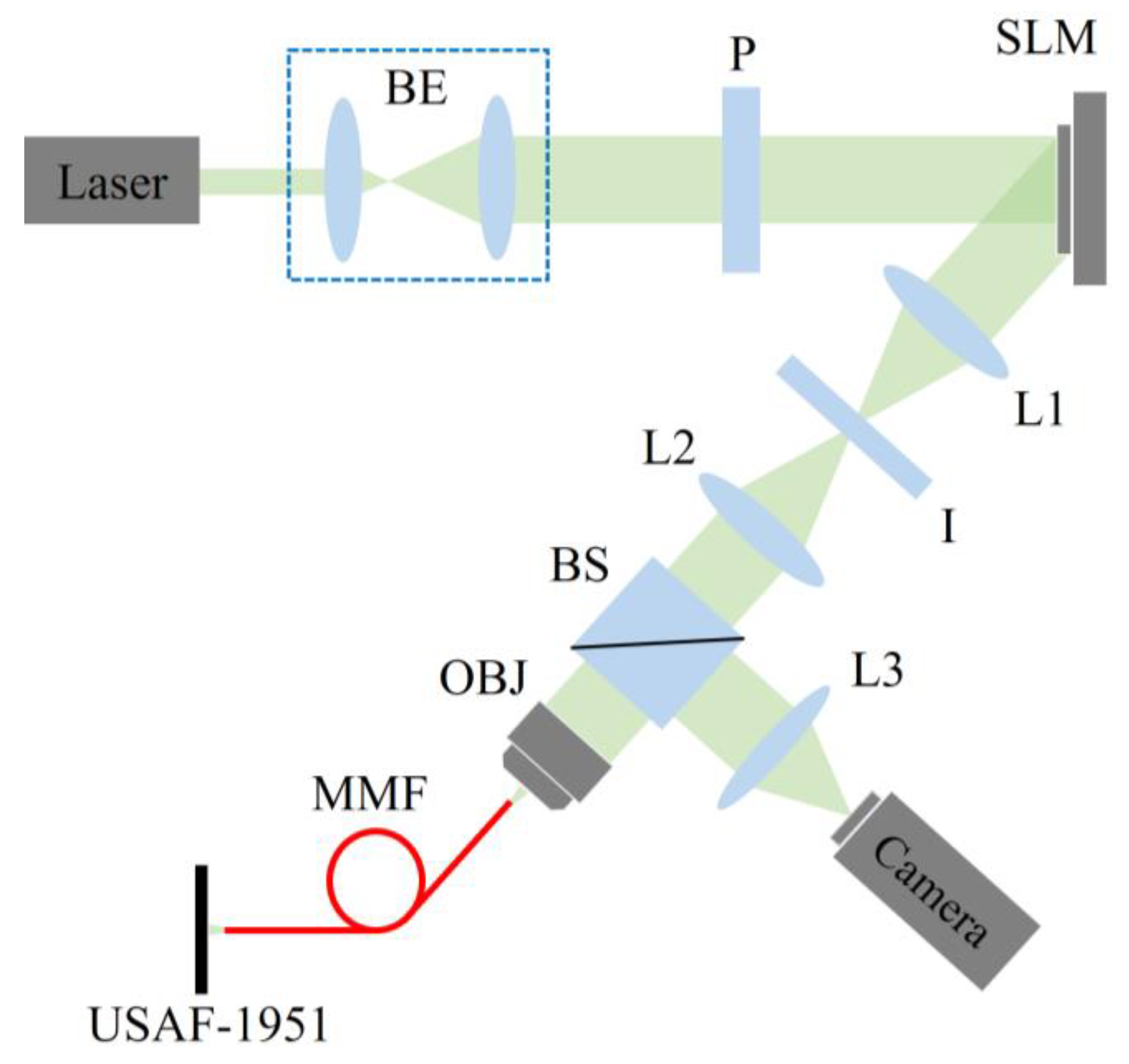
Based on the focused light field results, we constructed an optical system to perform MMF scanning imaging experiments. The optical setup for MMF scanning imaging follows an improved light field focusing system, as shown in Figure 6. The focused light spot generated by the MMF is used for focusing the reconstructed object, and the USAF-1951 object is translated by the translation table to locate different positions. Collecting the reflected light intensity information from each point with a CCD enables the reconstruction of the object’s surface reflectivity and achieves point-scanning imaging of the object. First, the beam from the laser (GL-100-T2, 532 nm) is processed by a beam expander and collimator to form a parallel beam, which then passes through a polarization beam splitter before reaching the SLM (HDSLM80R Plus, 1920 × 1200 pixels with a pixel size of 8 μm). The SLM modulates the phase of the incoming light, which then enters a 4f system. The light exiting the 4f system is focused by a microscope objective lens (4×, NA = 0.1) and coupled into the MMF (diameter = 50 μm, NA = 0.22) for transmission. The output light from the MMF illuminates the resolution target (USAF-1951, 1×) to perform point-scanning imaging. Reflected light from the resolution target is transmitted back through the MMF, focused by the microscope objective lens, and finally recorded by a CCD (MV-CA013-21UM, 1280 × 1024 pixels with a pixel size of 4.8 μm) after passing through a beamsplitter.
Point-scanning imaging was conducted at various positions on the USAF-1951 resolution target, targeting the fifth group, fifth line pair (single line width: 9.84 μm), the sixth group, first line pair (single line width: 7.81 μm), and the number “3” on the fifth group, third line pair. The imaging results are displayed in Figure 7. The images show high clarity in the reconstructed line pairs and the number “3”. The lines in the fifth group, fifth line pair, and sixth group, first line pair, are clearly visible with distinguishable gaps and no blurring or overlapping, indicating that the system achieves a resolution greater than 7.81 μm. The shape of the number “3” was also faithfully reproduced, maintaining clarity in the overall image structure. However, some noise points appear in the reconstructed images, likely due to variations in the MMF’s transmission matrix [32,36]. Such changes can degrade the performance of the CNN, and periodic retraining or calibration may be required to maintain focusing accuracy. Meanwhile, denoising algorithms such as Gaussian filtering or non-local averaging can be integrated into the processing pipeline for noise reduction. Future work will address these challenges by exploring strategies to mitigate the effects of transmission matrix variations, such as incorporating fiber deformation features into the training dataset or developing dynamic adaptive algorithms to adapt to changes in the hardware state.

5. Conclusions

In conclusion, we have developed an approach that replaces traditional MMF transmission matrix iteration methods by establishing a direct correlation between the phase applied to the SLM and the output light field of the MMF using a CNN. This method eliminates the need for complex optical adjustments, extensive measurements, and time-consuming iterative computations. Our experimental results demonstrate that this technique can rapidly generate a focused light field, with a generation time of just 200 ms and a focusing efficiency of 27.56%. Furthermore, in scanning imaging experiments using the USAF-1951 resolution target, the approach successfully performed point-scanning imaging of line pairs and digits with a resolution of 7.81 μm, validating its effectiveness for point-scanning imaging applications. The results of the method also suggest its potential for integration into more complex imaging systems, highlighting the importance of exploring the generality of this approach. Future work will therefore focus on optimizing the robustness and imaging resolution in dynamic environments, aiming to enhance the method’s applicability and performance across diverse situations. Overall, this method enables the rapid focusing and imaging of MMF fibers by efficiently computing the compensated phase, which is well suited for applications requiring real-time performance. This approach offers a novel solution for optical field modulation and imaging of MMF, paving the way for future developments in these fields.

Author Contributions

Conceptualization, H.S. and A.X.; methodology, R.T.; simulation, R.T.; validation, R.T. and A.X.; formal analysis, R.T.; investigation, A.X.; resources, H.S. and R.T.; data curation, R.T.; writing—original draft preparation, R.T. and A.X.; writing—review and editing, R.T. and H.S.; visualization, R.T.; supervision, H.S.; project administration, H.S.; funding acquisition, H.S. All authors have read and agreed to the published version of the manuscript.

Funding

This research was funded by the National Key Research and Development Program of China (Grant No. 2023YFB4604502), Postdoctoral Fellowship Program of CPSF (Grant No. GZC20242242) and Postgraduate Research & Practice Innovation Program of Jiangsu Province (Grant No. KYCX24_0646).

Institutional Review Board Statement

Not applicable.

Informed Consent Statement

Not applicable.

Data Availability Statement

The data are not publicly available due to privacy concerns but may be obtained from the authors upon reasonable request.

Conflicts of Interest

The authors declare no conflicts of interest.

References

  1. Stellinga, D.; Phillips, D.; Mekhail, S.; Selyem, A.; Turtaev, S.; Čižmár, T.; Padgett, M. Time-of-Flight 3D Imaging through Multimode Optical Fibers. Science 2021, 374, 1395–1399. [Google Scholar] [CrossRef]
  2. Moussa, N.O.; Mansuryan, T.; Hage, C.-H.; Fabert, M.; Krupa, K.; Tonello, A.; Ferraro, M.; Leggio, L.; Zitelli, M.; Mangini, F.; et al. Spatiotemporal Beam Self-Cleaning for High-Resolution Nonlinear Fluorescence Imaging with Multimode Fiber. Sci. Rep. 2021, 11, 18240. [Google Scholar] [CrossRef] [PubMed]
  3. Caramazza, P.; Moran, O.; Murray-Smith, R.; Faccio, D. Transmission of Natural Scene Images through a Multimode Fibre. Nat. Commun. 2019, 10, 2029. [Google Scholar] [CrossRef]
  4. Shekel, R.; Lib, O.; Gutiérrez-Cuevas, R.; Popoff, S.M.; Ling, A.; Bromberg, Y. Shaping Single Photons through Multimode Optical Fibers Using Mechanical Perturbations. APL Photonics 2023, 8, 096109. [Google Scholar] [CrossRef]
  5. Chapalo, I.; Stylianou, A.; Mégret, P.; Theodosiou, A. Advances in Optical Fiber Speckle Sensing: A Comprehensive Review. Photonics 2024, 11, 299. [Google Scholar] [CrossRef]
  6. Wen, Z.; Dong, Z.; Deng, Q.; Pang, C.; Kaminski, C.F.; Xu, X.; Yan, H.; Wang, L.; Liu, S.; Tang, J.; et al. Single Multimode Fibre for in Vivo Light-Field-Encoded Endoscopic Imaging. Nat. Photonics 2023, 17, 679–687. [Google Scholar] [CrossRef]
  7. Leite, I.T.; Turtaev, S.; Boonzajer Flaes, D.E.; Čižmár, T. Observing Distant Objects with a Multimode Fiber-Based Holographic Endoscope. APL Photonics 2021, 6, 036112. [Google Scholar] [CrossRef]
  8. Du, Y.; Turtaev, S.; Leite, I.T.; Lorenz, A.; Kobelke, J.; Wondraczek, K.; Čižmár, T. Hybrid Multimode—Multicore Fibre Based Holographic Endoscope for Deep-Tissue Neurophotonics. Light Adv. Manuf. 2022, 3, 408–416. [Google Scholar] [CrossRef]
  9. Choutagunta, K.; Kahn, J.M. Designing High-Performance Multimode Fibers Using Refractive Index Optimization. J. Light. Technol. 2021, 39, 233–242. [Google Scholar] [CrossRef]
  10. Mondal, P.; Mishra, V.; Varshney, S.K. Nonlinear Interactions in Multimode Optical Fibers. Opt. Fiber Technol. 2020, 54, 102041. [Google Scholar] [CrossRef]
  11. Rademacher, G.; Luís, R.S.; Puttnam, B.J.; Ryf, R.; van der Heide, S.; Eriksson, T.A.; Fontaine, N.K.; Chen, H.; Essiambre, R.-J.; Awaji, Y.; et al. A Comparative Study of Few-Mode Fiber and Coupled-Core Multi-Core Fiber Transmission. J. Light. Technol. 2022, 40, 1590–1596. [Google Scholar] [CrossRef]
  12. Zhang, L.; Xu, R.; Wang, K.; Xu, B.; Chen, R.; Sarwar, R.; Zhang, D. Research on Image Transmission Mechanism through a Multimode Fiber Based on Principal Component Analysis. Opt. Lasers Eng. 2020, 134, 106197. [Google Scholar] [CrossRef]
  13. Resisi, S.; Popoff, S.M.; Bromberg, Y. Image Transmission Through a Dynamically Perturbed Multimode Fiber by Deep Learning. Laser Photonics Rev. 2021, 15, 2000553. [Google Scholar] [CrossRef]
  14. Li, S.; Saunders, C.; Lum, D.J.; Murray-Bruce, J.; Goyal, V.K.; Čižmár, T.; Phillips, D.B. Compressively Sampling the Optical Transmission Matrix of a Multimode Fibre. Light Sci. Appl. 2021, 10, 88. [Google Scholar] [CrossRef]
  15. Tran, V.; Wang, T.; Nazirkar, N.P.; Bassène, P.; Fohtung, E.; N’Gom, M. On the Exploration of Structured Light Transmission through a Multimode Fiber in a Reference-Less System. APL Photonics 2023, 8, 126111. [Google Scholar] [CrossRef]
  16. Resisi, S.; Viernik, Y.; Popoff, S.M.; Bromberg, Y. Wavefront Shaping in Multimode Fibers by Transmission Matrix Engineering. APL Photonics 2020, 5, 036103. [Google Scholar] [CrossRef]
  17. Wang, D.; Zhou, E.H.; Brake, J.; Ruan, H.; Jang, M.; Yang, C. Focusing through Dynamic Tissue with Millisecond Digital Optical Phase Conjugation. Optica 2015, 2, 728–735. [Google Scholar] [CrossRef] [PubMed]
  18. Büttner, L.; Thümmler, M.; Czarske, J. Velocity Measurements with Structured Light Transmitted through a Multimode Optical Fiber Using Digital Optical Phase Conjugation. Opt. Express 2020, 28, 8064–8075. [Google Scholar] [CrossRef]
  19. Ma, C.; Di, J.; Li, Y.; Xiao, F.; Zhang, J.; Liu, K.; Bai, X.; Zhao, J. Rotational Scanning and Multiple-Spot Focusing through a Multimode Fiber Based on Digital Optical Phase Conjugation. Appl. Phys. Express 2018, 11, 062501. [Google Scholar] [CrossRef]
  20. Cui, M. Parallel Wavefront Optimization Method for Focusing Light through Random Scattering Media. Opt. Lett. 2011, 36, 870–872. [Google Scholar] [CrossRef] [PubMed]
  21. Cheng, S.; Zhong, T.; Woo, C.M.; Zhao, Q.; Hui, H.; Lai, P. Long-Distance Pattern Projection through an Unfixed Multimode Fiber with Natural Evolution Strategy-Based Wavefront Shaping. Opt. Express 2022, 30, 32565. [Google Scholar] [CrossRef] [PubMed]
  22. Yu, H.; Yao, Z.; Sui, X.; Gu, G.; Chen, Q. Focusing through Disturbed Multimode Optical Fiber Based on Self-Adaptive Genetic Algorithm. Optik 2022, 261, 169129. [Google Scholar] [CrossRef]
  23. Fayyaz, Z.; Mohammadian, N.; Salimi, F.; Fatima, A.; Tabar, M.R.R.; Avanaki, M.R.N. Simulated Annealing Optimization in Wavefront Shaping Controlled Transmission. Appl. Opt. 2018, 57, 6233–6242. [Google Scholar] [CrossRef] [PubMed]
  24. Di Leonardo, R.; Bianchi, S. Hologram Transmission through Multi-Mode Optical Fibers. Opt. Express 2011, 19, 247. [Google Scholar] [CrossRef]
  25. Mahalati, R.N.; Askarov, D.; Wilde, J.P.; Kahn, J.M. Adaptive Control of Input Field to Achieve Desired Output Intensity Profile in Multimode Fiber with Random Mode Coupling. Opt. Express 2012, 20, 14321. [Google Scholar] [CrossRef]
  26. Yin, Z.; Liu, G.; Chen, F.; Liu, B. Fast-Forming Focused Spots through a Multimode Fiber Based on an Adaptive Parallel Coordinate Algorithm. Chin. Opt. Lett. 2015, 13, 071404. [Google Scholar] [CrossRef]
  27. Geng, Y.; Zhao, G.; Chen, H.; Xu, C.; Zhuang, B.; Ren, L. High-Speed Focusing and Scanning Light through a Multimode Fiber Based on Binary Amplitude-Only Modulation Parallel Coordinate Algorithm. Appl. Phys. B 2019, 125, 83. [Google Scholar] [CrossRef]
  28. Rahmani, B.; Loterie, D.; Konstantinou, G.; Psaltis, D.; Moser, C. Multimode Optical Fiber Transmission with a Deep Learning Network. Light Sci. Appl. 2018, 7, 69. [Google Scholar] [CrossRef] [PubMed]
  29. Rothe, S.; Zhang, Q.; Koukourakis, N.; Czarske, J.W. Deep Learning for Computational Mode Decomposition in Optical Fibers. Appl. Sci. 2020, 10, 1367. [Google Scholar] [CrossRef]
  30. Xu, R.; Zhang, L.; Chen, Z.; Wang, Z.; Zhang, D. High Accuracy Transmission and Recognition of Complex Images through Multimode Fibers Using Deep Learning. Laser Photonics Rev. 2023, 17, 2200339. [Google Scholar] [CrossRef]
  31. Zhu, R.; Luo, J.; Zhou, X.; Feng, H.; Xu, F. Anti-Perturbation Multimode Fiber Imaging Based on the Active Measurement of the Fiber Configuration. ACS Photonics 2023, 10, 3476–3483. [Google Scholar] [CrossRef]
  32. Fan, P.; Wang, Y.; Ruddlesden, M.; Wang, X.; Thaha, M.A.; Sun, J.; Zuo, C.; Su, L. Deep Learning Enabled Scalable Calibration of a Dynamically Deformed Multimode Fiber. Adv. Photonics Res. 2022, 3, 2100304. [Google Scholar] [CrossRef]
  33. Zhang, Y.; Gong, Z.; Wei, Y.; Wang, Z.; Hao, J.; Zhang, J. Image Transmission through a Multimode Fiber Based on Transfer Learning. Opt. Fiber Technol. 2023, 79, 103362. [Google Scholar] [CrossRef]
  34. Chen, H.; Geng, Y.; Xu, C.; Zhuang, B.; Ju, H.; Ren, L. Efficient Light Focusing through an MMF Based on Two-Step Phase Shifting and Parallel Phase Compensating. Appl. Opt. 2019, 58, 7552–7557. [Google Scholar] [CrossRef] [PubMed]
  35. Guo, S.; Stern, R.; Zhang, H.; Pang, L. Speedy Light Focusing through Scattering Media by a Cooperatively FPGA-Parameterized Genetic Algorithm. Opt. Express 2022, 30, 36414–36428. [Google Scholar] [CrossRef] [PubMed]
  36. Farahi, S.; Ziegler, D.; Papadopoulos, I.N.; Psaltis, D.; Moser, C. Dynamic Bending Compensation While Focusing through a Multimode Fiber. Opt. Express 2013, 21, 22504. [Google Scholar] [CrossRef] [PubMed]
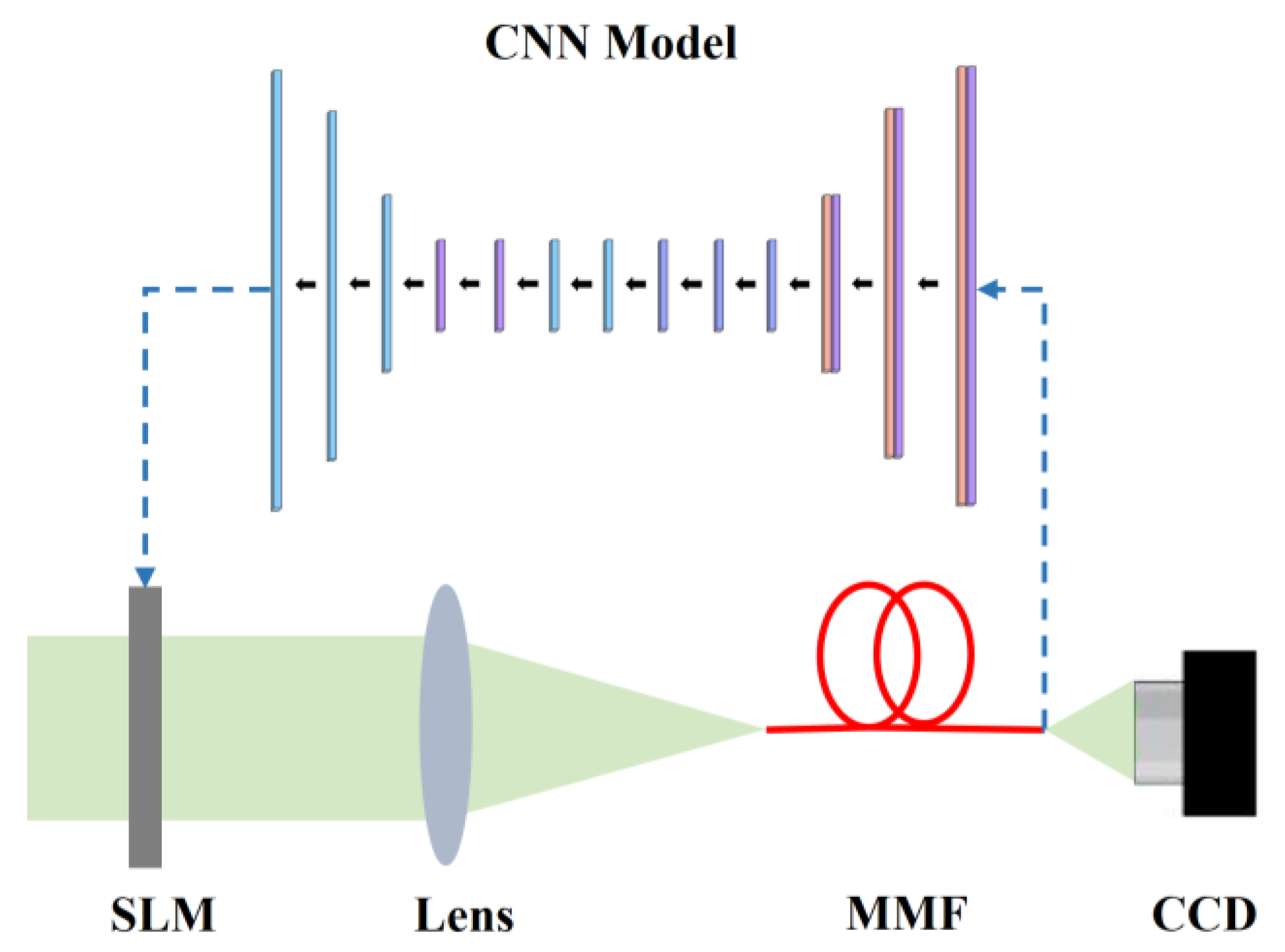
Figure 1. Principle of optical field focusing in MMF based on CNN model. The arrows indicate the direction of the data flow.
Photonics 12 00041 g001
Figure 2. Detailed structure of the CNN model.
Photonics 12 00041 g002
Figure 3. CNN model training results: (a) convergence curve of the loss function; (b) output-focused light field from the MMF (simulation); (c) intensity variation curve of the focused light field (simulation).
Photonics 12 00041 g003
Figure 4. Experimental setup for focused light field with multimode fiber. Components: laser (532 nm wavelength); BE (beam expander); P (polarizer); SLM (spatial light modulator); L1–L3 (lens); I (aperture); OBJ1, OBJ2 (microscope objective lens); MMF (multimode fiber); camera.
Photonics 12 00041 g004
Figure 5. The experiment results of focused light field. (a) Speckle field directly output by the MMF. (b) Focused light field from the MMF after CNN modulation (experiment). (c) Intensity distribution of the focused light field cross-section (experiment).
Photonics 12 00041 g005
Figure 6. Experimental setup for focused spot scanning imaging with multimode fiber. Components: laser (532 nm wavelength); BE (beam expander); P (polarizer); SLM (spatial light modulator); L1–L3 (lens); I (aperture); BS (beam splitter); OBJ (microscope objective lens); MMF (multimode fiber); USAF-1951 (resolution target); camera.
Photonics 12 00041 g006
Figure 7. The experiment results of scanning imaging. (a) Fifth group, fifth line pair (line width: 9.84 μm). (b) Number “3” on the fifth group, third line pair. (c) Sixth group, first line pair (line width: 7.81 μm).
Photonics 12 00041 g007
Table 1. Comparison of focused spot generation time and focusing efficiency with other methods.
MethodAverage Generation Time of Light Field (s)Focusing
Efficiency (%)
Adaptive Parallel Coordinate algorithm [26]3.3617.5
Two-Step Phase-Shifting Method [31]0.6521.6
FPGA-parameterized genetic algorithm [32]14/
Our work0.227.56
Disclaimer/Publisher’s Note: The statements, opinions and data contained in all publications are solely those of the individual author(s) and contributor(s) and not of MDPI and/or the editor(s). MDPI and/or the editor(s) disclaim responsibility for any injury to people or property resulting from any ideas, methods, instructions or products referred to in the content.