Review

Singularities in Computational Optics

Optics and Photonics Center, Indian Institute of Technology Delhi, New Delhi 110016, India
*
Author to whom correspondence should be addressed.
Current address: Singular Optics Lab, Department of Physics, Indian Institute of Technology Delhi, New Delhi 110016, India.
Photonics 2025, 12(2), 96; https://doi.org/10.3390/photonics12020096
Submission received: 26 November 2024 / Revised: 8 January 2025 / Accepted: 15 January 2025 / Published: 22 January 2025
(This article belongs to the Special Issue Structured Light Beams: Science and Applications)

Abstract

:
Phase singularities in optical fields are associated with a non-vanishing curl component of phase gradients. Huygen’s diverging spherical wavefronts that primary/secondary point sources emit, during propagation, a have zero curl component. Therefore, the propagation of waves that contain phase singularities exhibits new exciting features. Their effect is also felt in computational optics. These singularities provide orbital angular momentum and robustness to beams and remove degeneracies in interferometry and diffractive optics. Recently, the improvisations in a variety of computation algorithms have resulted in the vortices leaving their footprint in fast-expanding realms such as diffractive optics design, multiplexing, signal processing, communication, imaging and microscopy, holography, biological fields, deep learning, and ptychography. This review aims at giving a gist of the advancements that have been reported in multiple fields to enable readers to understand the significance of the singularities in computation optics.

1. Introduction

1.1. Singularities

Singularity is a point in a field at which a physical/mathematical quantity is undefined but exhibits a large gradient around it [1]. In optics, singularity usually refers to a phase singularity, which is a point at which the phase is indeterminate. There can be polarization singularity, coherence singularity, Stokes singularity, and so on—all referring to optical fields. Phase singularity is frequently called an optical vortex, and the beam that carries it at its center is referred to as a vortex beam/doughnut beam or an OAM beam. The intriguing fact is that, at the singular point, the amplitude is zero and the wavefront is helical, possessing orbital angular momentum (OAM) [2], which is transferable. For a phase singular beam, the topological charge is given by
ϕ · d l = 2 π m
where ϕ is the phase, d l is the line element along the path of integration, and ϕ is the phase gradient vector field. The topological charge of the singularity is m, representing the number of 2 π windings of the wavefront twist around the vortex core. Because of the nature of Equation (1), the phase difference between any two points is ambiguous, as the integral becomes path dependent. This means × ϕ 0 , and in the neighborhood region, the gradient field has a non-zero curl or circulating phase gradient. The presence of vortices (singularities) makes the phase distribution ϕ ( x , y ) special. Since the phase ϕ is a scalar, the vector field, namely, the phase gradient field ϕ created from it, normally satisfies × ϕ = 0 . This is true in the absence of any sources that can generate gradient field lines (vector field), but when there is a singularity in the region within the closed path, the curl is not zero. As an example, consider an electrostatic field where E · d l = 0 . However, when sources are present, E · d l = d B d t , which is the e.m.f. By going from statics to dynamics, apart from charges and currents, we see that time-varying fields behave like sources of vector fields; i.e., a time-varying electric field produces a magnetic field and vice versa. Then through the Stokes theorem, we see that the curl of the gradient is not zero. In this analogy, a phase is like electric potential, phase gradients are like electric field lines, and phase contours are equipotential surfaces. In optics, the phase contour surfaces are wavefronts, and in interferometry, the fringe patterns are phase (difference) contours (seen as curves in 2D plane) [1]. Hence, in interference patterns involving singularities, new fringes can be seen starting from a singularity like in a fork fringe pattern or in a spiral fringe pattern.
A beam with a complex field of the form exp { i m θ } carries an OAM of m ħ per photon [3]. There are a number of review articles on optical phase singularities [4,5,6,7,8,9]. Singular beams have many fascinating features. A beam embedded with a phase singularity connects the wavefronts, which are otherwise separated from each other by λ distance. The presence of a singularity in a wavefront has a global influence on the wavefront. The high spatial phase gradient, near the core, exceeds the highest spatial frequency of 1 λ that a non-singular beam would have. The phase gradient blows up at the core. Any parameter taking an infinite value is a menace in computations. In spite of this, singularities have proven useful in many applications. Random complex fields host a large number of phase singularities. In laser speckles, almost every dark spot contains a phase vortex. Therefore, a doughnut beam hosts a single vortex and a random field hosts a large number of vortices.

1.2. Computation Optics

Computational optics is an interdisciplinary field that combines optics and programming algorithms to analyze, simulate, and design methodologies [10]. This encompasses a computer-assisted synthesis/design of beams, capture, display, analysis, and assessment of the amplitude and phase information of objects. The current computing technology has revolutionized imaging systems and steadily led to the digitization of optical imaging systems. This field has aided in the analysis and design of optical systems using computational tools and various algorithms. The current computing technology has permeated all aspects of imaging systems. Generally, an object to be imaged is illuminated by any radiation source producing waves, which, on interaction with the object, get encoded with the information about the object. This information may be of any form, like space-time variations of intensity, phase, polarization, spectrum, and coherence properties, and is not directly available. The prime goal of any imaging system is to extract the image of the object from this encoded information. Initial efforts involved improving the traditional imaging hardware used, but thanks to the fast processing power of computers, the retrieval has shifted to the digital reconstruction of data from an optical imaging sensor or vice versa.

1.3. Organization of This Article

Although we wish to cover topics that involve only numerical computations, in many cases, it is now hard to draw a demarcation line so as to segregate between experimental optics and computation optics. Therefore, we try to focus on topics that involve both computation/theory and experiments. For example, the first computer-generated hologram (CGH) by Lohmann and Paris [11] involves numerical computing of the hologram transmittance function of the hologram, but the reconstruction is performed optically. Later, the same terminology was used in a different context that the hologram is recorded optically and the reconstruction is performed numerically. Holographic microscopy [12] is a typical example that enables quantitative phase estimation, where recording is optical and reconstruction is numerical. When the photographic/holographic medium was used for recording the hologram, the transmittance function of the element had amplitude variation only. Lohmann’s detour phase hologram is a binary amplitude hologram. However, later, with the advent of devices like spatial light modulators (SLMs), or methods like bleaching the photographic plates and lithography, phase transmittance and complex transmittance have become a reality. This has enabled researchers to realize optical elements whose transmittance function is computed and displayed (say on SLMs), where conventional fabrication of such elements is not possible. Keeping these points in mind, we have chosen topics based on our judgment and included them in this article.
The article starts with a brief introduction to singularities, especially phase singularities and computation optics. Singularities in computational optics—the main theme of the paper—form the second section, which lists 20 subsections. Since a wide range of topics are covered, some sections may look disconnected. Flowcharts of algorithms are not presented; instead, relevant references are listed. At the end, concluding remarks are made.

2. Singularities in Computational Optics

A phase singularity, also termed as a vortex beam, has a unique helical wavefront. Owing to this helical phase, the intensity distribution of the beam is zero at the center, which remains zero on propagation, rendering it a doughnut structure. Since its advent, it has never left the center stage and continues to keep embracing newer fields due to its intriguing characteristics. Phase measurement is a critical challenge in various optical fields, such as microscopy, imaging, wavefront sensing, imaging through turbulence, and metrology. It is typically performed using optical interferometry, where the phase of an unknown wavefront is determined by comparing it with a reference wave of a known phase distribution. Additionally, there are numerous non-interferometric methods that rely on one or more intensity measurements. However, these non-interferometric techniques require iterative numerical algorithms to estimate the phase. Similarly, phase retrieval is achieved by interferometric or numerical methods. Phase retrieval processes tend to be either iterative as in the Gerchberg–Saxton (GS) algorithm [13] or deterministic as in the transport of intensity equation (TIE). There are many other algorithms that have been used in conjunction with phase singularities, like the Yang–Gu algorithm [14,15], hybrid input–output (HIO) algorithm [16], genetic algorithm [17], Iterative Fourier transform (IFT) algorithm [18], complexity guided phase retrieval [19], and nonlinear reconstruction algorithm [20]. There are some compendious reviews that throw light on the methodology and functioning of the commonly used iterative algorithms [21,22,23,24,25]. In the subsequent subsections, we have tried to give an idea about the various fields that use singularities in one form or the other in computation optics.

2.1. Diffusers

Diffused illumination is important in optics as objects illuminated by diffused light do not cast a well-defined shadow. In holography, the use of diffused illumination is a milestone development [26]. It is used for phase randomization of the fields recorded in the hologram. Such holograms have the property that if the hologram is broken to pieces, the object can be reconstructed from each of the broken pieces. This is also called redundancy. Object transparency with a random phase ensures that every part of the recording medium has contributions from every point of the object, thereby increasing the redundancy in the hologram recording. Ground glass plates are normally used as diffusers to produce diffused light, which contains a grainy structure called speckles. Each of the dark regions of the speckle contains optical vortices [27,28]. Though the field distribution is random and the vortex distribution in the field appears random, they are well correlated [29,30,31,32,33]. Further, diffused illumination is used to homogenize fields, which propagate (diffuse) in all directions. The presence of vortices in such diffused light creates dark spots in the speckle pattern, and it is desired to have diffusers that produce speckle-free light fields that can serve as an extended source.
Diffusers are designed [34,35,36,37] to produce random phase illumination in holography. A general purpose diffuser [37] was designed that was suitable to use with any objects unlike object-specific diffusers [38]. In Figure 1, an image of a binary amplitude object and the same object reconstructed from a CGH made using diffused illumination of the object is shown. The dark spots on the reconstructed object are due to speckles, and they contain optical phase singularities. The design of diffusers that do not produce dark spots on the object is numerically computed with a series of pseudorandom phase sequences using different constraints [36], and a theoretical analysis of their power spectra was carried out. Analysis of pseudorandom phases that are band-limited, with typical forms of the power spectrum of an almost rectangular shape, was achieved.

2.2. Computer-Generated Hologram and Phase Retrieval

In computer-generated holography, the holographic transmittance function is mathematically computed and the hologram is realized. Most of the reported computer-generated holograms (CGH) are Fourier transform holograms. The reconstruction is performed optically. By designing CGH, it is possible to generate wavefronts that are difficult to realize by using conventional optical elements. Such synthesized wavefronts can be used to reduce the complexity in the fringe analysis in optical metrology. The hologram transparency and the reconstructed field in CGH are connected by Fourier transform relation.
Similarly, let us consider another problem, namely, the phase retrieval problem, in which two fields are connected by Fourier transform relation. Here, the amplitude and phase of an unknown field have to be constructed from its Fourier plane intensity distribution. In other words, given the Fourier magnitude of an unknown field, the unknown complex field has to be constructed. Normally, the field is the one received by the aperture of an optical system, and the captured intensity pattern at the Fourier plane is used to retrieve the phase.
In these two problems, an iterative Fourier transform algorithm is used [39,40]. In CGH, the constraints are the finite size of the hologram at the hologram plane and the desired intensity distribution at the reconstructed object. In the case of phase retrieval, the aperture size is at a plane, where the field is captured and its Fourier magnitude is the two constraints. Figure 2 depicts the two cases where IFTA is used.

2.3. Vortex Stagnation Problem in Computer-Generated Hologram (CGH) Design

The iterative Fourier transform algorithm (IFTA) by Gerschberg and Saxton [13] is used to design phase-only CGH to give a desired diffraction intensity pattern. IFTA is also used in electron microscopy, wavefront sensing, astronomy, crystallography, digital holography, and diffractive optics. The CGH design problem is slightly different from the standard Fourier phase retrieval problem in that the desired intensity pattern is often an image with a somewhat uniform intensity level. In the phase retrieval problem, the diffraction pattern of natural objects typically has a peak intensity near zero spatial frequency.
The IFTA iteration starts by assuming a constant amplitude random phase distribution as the initial guess. The phase of the diffraction pattern is a free parameter in this problem. Using the initial random field, the complex field at the display plane is computed. Since the two fields are connected by FT, in each iteration, both computed fields are modified using appropriate constraints. For a certain type of Fourier intensity, constraints, and initial phase distributions, the iterative algorithm fails to converge to a good solution and stagnates [41,42,43]. A good solution satisfies the constraints in both domains. One of the reasons attributed to this stagnation is the presence of optical phase singularities in the display plane where the diffraction intensity is to be observed. These are robust features and are not removable by further iterations.
Solution to the vortex stagnation problem in IFTA: Once the field stagnates, what is done is that a search for phase singularities in the field is carried out. Once the charge, sign, and location of the singularity is determined, the whole field is multiplied with a conjugate vortex field, with its core aligning with the location of the core of the vortex that is found. A vortex core is characterized by an intensity null point in the field. This way, the singularity-induced stagnation problems can be tackled [43] and the iteration is carried till the desired metric is reached.

2.4. Phase Unwrapping in the Presence of Vortices

Phase variations in optical fields are normally not restricted between π ψ π , and can exceed several multiples of 2 π as the peak-valley path variation can be several λ s. However, in computation optics, the phase variation is normally presented to be between the phase levels of π ψ π , and this phase variation is referred as wrapped phase variation. This phase variation clearly represents the original wavefront, because the 2 π phase discontinuity as seen in the distribution is actually not a phase discontinuity. In the original phase distribution, a modulo 2 π operation is carried out, and the remainder is depicted in the phase distributions. The construction of a single wavefront from this phase distribution is possible through the process called phase unwrapping. In the wrapped phase, at the 2 π phase discontinuity (but actually, they are not), the pieces of the wavefronts on either side of the discontinuity are connected (stitched) to either a preceding or succeeding wavefront and a continuous wavefront is built.
In complex fields that do not contain phase singularities, the phases at point a and point b are connected by the relation
ψ ( b ) ψ ( a ) = a b ψ · d l
Hence, the phase at point b on the wavefront is given by ψ ( b ) = a b ψ · d l + ψ ( a ) .
In a phase unwrapping jargon, the presence of phase singularities is due to phase residues. These residues are actually phase residues that are different from the residues that occur in a complex variable theory. Actually, these phase residues are phase singularities in the complex field distribution. Ghiglia et al. [44] noticed these phase inconsistencies in two-dimensional phase unwrapping in 1987, and they were named as residues by Goldstein, Zebker, and Werner [45] in 1988. Huntley et al. named them as sources of discontinuity [46].
In fact, one can notice that the residue theorem that is used in phase unwrapping is similar to the definition of topological charge in singular optics. It states that the closed path integral around a phase residue equals the integer multiple of 2 π , as follows:
ψ ( r ) · d r = 2 π × S p
where S p is the sum of the enclosed phase residues (topological charge) inside the contour. The topological charge of a vortex can be either a positive or negative integer, and in a similar way, the phase residue can be positive or negative. Positive residues can be canceled by negative residues through the procedure explained earlier.
When the phase residue charges are balanced in a region, the line integral is zero. This means that inside the closed path of the integral, an equal number of positive and negative residues are there. Therefore, by converting the line integral to a surface integral, using the Stokes theorem,
ψ ( r ) · d r = ( × ψ ( r ) ) . d a = 0 .
The phase gradient field becomes curl-less, and hence, the vector field is ir-rotational or conservative. The path dependency of the integral also vanishes. In Equation (4), d a is the area vector. Now Equation (2) can be applied to obtain the unwrapped phase distribution.
This balancing of the phase residue charges can be carried out by first identifying the presence of residues, and opposite charged residues can be introduced inside the closed loop by numerical methods [47,48]. The identification of residues can be done by going point by point on the field distribution and evaluating the closed-loop integral each time for a non-zero accumulated phase as is done in singular optics [42,43,48] or by using the Helmholtz–Hodge decomposition method [49].

2.5. Diversity Mechanism Provided by Vortex Phase

Several advantages of using a vortex phase originate from its Hilbert transform-like behavior in two dimensions. Consider a two dimensional real-valued image g ( x , y ) that has a radial carrier frequency given by ρ 0 , which can vary from zero frequency up to maximum frequency, as allowed by the image size. In a manner similar to the one-dimensional case, we can introduce the notion of Hilbert transform in two dimensions. In one dimension, the Hilbert transform converts a cosine function to sine function and vice versa, or in other words, the quadrature signal obtained via the Hilbert transform has positions of minima and maxima interchanged with the original signal. In [50], it was shown that a charge 1 vortex phase filter applied to g ( x , y ) produces an equivalent two-dimensional quadrature signal. In line with Mandel’s theorem on Hilbert transforms [51], this work showed that the vortex filter choice is special in the sense that the resultant two-dimensional complex signal has the smoothest varying envelope. Here, the envelope fluctuation is computed in Fourier space as a second moment of energy in the signal surrounding a delta ring at ρ = ρ 0 . The Hilbert transform-like diversity provided by the vortex phase filter provides several opportunities for using a vortex phase as a filter to obtain maximally diverse information from diffraction or imaging measurements. This diverse information can be effectively combined by suitable algorithms to obtain imaging performance surpassing the equivalent diffraction-limited system. We will see several examples of this property of the vortex phase filter in the following sections.

2.6. Phase Retrieval by Spiral Phase Diversity

Phase measurement is an important problem in optics. In microscopy, imaging, wavefront sensing, imaging through turbulence, and metrology, the phase measurement is performed by optical interferometry. Methods based on single or multiple intensity measurements can also be used for phase retrieval. These are non-interferometric methods that rely on an iterative numerical procedure for phase estimation.
An iterative algorithm based on the Gerchberg and Saxton method [13] for phase retrieval uses a single intensity measurement and object constraints. Non-interferometric methods such as the transport of intensity equation (TIE) [52,53,54] use multiple intensity patterns at different planes that are axially separated for phase estimation. In iterative schemes [55,56], multiple (upto 20) intensity measurements in the Fresnel zone are used for robust phase reconstruction. Defocus diversity near the focal plane uses two defocus measurements [57] for complex field construction. The acquisition of non-redundant information from multiple intensity measurements, with each intensity pattern providing different information, is useful. When an optical vortex is used in the scheme, the intensity distribution provides a highly diverse information from the one that is obtained without a vortex in the setup, leading to a good-quality phase recovery in a minimal number of intensity measurements.
A complex object wavefront denoted by g ( r , θ ) is incident on the aperture C ( r , θ ) of a thin convex lens. Two diffraction patterns are obtained—one with and the other without a vortex phase plate placed at the diffracting apertures. A vortex phase suppresses the zero frequency component of the object and provides diverse information that the other pattern does not capture. The spiral phase diversity mechanism explained in the previous section is responsible for a good phase recovery. The knowledge of the two intensity measurements along with the aperture function C ( r , θ ) constraint is used to estimate the unknown complex function g ( r , θ ) by an iterative algorithm similar to the GS algorithm [13]. Numerical simulations for the new spiral-phase diversity technique have been presented in Figure 3. This method is effective for the imaging of both amplitude/phase objects [58].
There are reports showing that the use of higher-order vortex beams greatly improves the accuracy of the phase retrieval. A phase diversity (PD) phase retrieval method based on numerical optimization algorithms (NOAs) has been used to determine the aberrations of an optical system by imaging a known coherent object. A spiral phase mask is used as a diversity (along with a blazed grating serving as the second mask), enhancing phase retrieval. The spiral phase mask introduces a phase singularity of order l at the center of the image, which can also be a Zernike aberration or a combination of both. The blazed diffraction grating does the work of spatially separating the zeroth and first diffraction orders [59].

2.7. Twin Stagnation Free Phase Retrieval

Fourier phase retrieval refers to the problem of determining a complex-valued object g ( x , y ) using the magnitude | G ( f x , f y ) | of its two-dimensional Fourier transform. The phase retrieval problem has a long history and has important applications in crystallography, astronomical imaging, biomedical imaging, and microscopy, coherent diffraction imaging, and metrology. While the early phase retrieval algorithms like the error reduction and the hybrid input–output (HIO) algorithm [16] are now nearly 50 years old, practical systems based on an iterative phase retrieval algorithm are not readily available, mainly due to the stagnation problems associated with them. One of the most difficult stagnation problems [40] associated with the twin image arises since the two objects g ( x , y ) and g * ( x , y ) have the same Fourier magnitude | G ( f x , f y ) | . Both the solutions compete with each other and appear simultaneously in the solution of IFT algorithms in a non-separable fashion. The twin-stagnated solution does not make progress towards either of the two solutions. The stagnation issues in the IFT algorithm when applied to a phase-only CGH (Computer-Generated Hologram) design problem are discussed in Section 2.3. It is well known [60] that the IFT iterations lead to the development of phase vortices in the vicinity of isolated zeros in the Fourier magnitude. Further, the incorrect relative orientation of the phase vortices is known to cause stagnation problems in phase retrieval. Wackerman [61,62] introduced elaborate procedures to identify and nullify the phase vortices near isolated zeros in the Fourier magnitude data. Such a procedure in the context of a CGH design problem is already mentioned in Section 2.3 above [43]. In addition to being tedious, such procedures are difficult to implement if the zeros of a Fourier magnitude are embedded within the noise in the Fourier magnitude data. Stagnation problems in phase retrieval were discussed in detail in [40], where one of the suggested solutions is to use reduced area support in initial iterations, followed by the use of a full support window. This approach is interesting but is not guaranteed to avoid a twin problem, particularly for phase objects with large phase variation. In a recent work [63], it was shown that the stagnation problems with the IFT algorithms can be eliminated if a charge 1 vortex phase is used for illumination instead of the usual plane wave illumination. The vortex illumination intentionally introduces an isolated zero near the dc region in the Fourier magnitude where most energy in the data is usually localized for natural objects. When Fourier magnitude data corresponding to vortex illumination are used for phase retrieval, the early iterations of the IFT algorithm naturally latch onto a vortex of particular orientation (clockwise or anti-clockwise) near this isolated zero, and the solution associated with the corresponding twin gains prominence. The further IFT iterations refine the solution but do not bring the other twin into the reconstruction. The undesired isolated zeros in the CGH design problem are now used to advantage by intentionally introducing an isolated zero in the data in the high energy concentration region. In Figure 4, we illustrate a simulation of a vortex illumination-based phase retrieval concept for a binary test phase object “A”. The test object has two phase levels, 0 and 2 π / 3 . When phase retrieval is performed with plane wave diffraction data, the resultant solution is invariably twin-stagnated, as illustrated in Figure 4a. On the other hand, when vortex illumination is used, the twin stagnation is never observed and a high-quality phase reconstruction is obtained, as shown in Figure 4b. This solution has an extra phase vortex, which may be eliminated by simple subtraction at the end of the iterative process to yield the estimate of the original object, as shown in Figure 4c. The near-deterministic behavior of an IFT algorithm with vortex illumination opens up several new device realization possibilities.

2.8. Underwater Communication

Phase singularities, or OAM beams as commonly referred to in the field of communication, have been explored in many ways for aerial and underwater communication [64,65,66,67,68,69,70]. Building a high-capacity communication link is the major requirement of underwater optical communication (UWOC), and OAM beams have been applied exactly to achieve this target [71,72]. However, the major challenge faced by a wavefront-sensitive OAM beam is the significant distortion due to oceanic turbulence (OT), resulting in considerable intermodal crosstalk that degrades the UWOC performance. This results in underwater images having poor contrast and resolution. To sharpen the images, an intelligent optimization algorithm called vortex optimization algorithm was used in order to achieve a contrast improvement in the RGB space. The underwater image is separated into RGB color components, and then the contrast for each component has been improved [73] as shown in Figure 5.
For the same purpose, Huan Chang et al. propose an adaptive optics (AO)-based correction approach with a phase retrieval algorithm (PRA) to compensate for the distorted OAM beams induced by OT. Two PRAs, the Gerchberg–Saxton algorithm (GSA) and the hybrid input–output algorithm (HIOA), are utilized to reconstruct the distorted phase front of the OAM beam. The compensation performance of HIOA-based AO is superior to that of GSA-based AO in terms of convergence performance [74]. This is evident from Figure 6.
Yang et al. investigated the effects of absorbent and weak turbulent seawater channels on the OAM mode carried by a perfect optical vortex (POV) based on the Rytov approximation. It was shown that an underwater communication link with POV as the signal carrier can obtain high receiving probability by adopting a long signal wavelength in intervals of “seawater window wavelength”, a low OAM quantum number, a POV with a larger ring radius, and a transmitter and a receiver with a smaller aperture. Additionally, the transmission distance of the OAM mode carried by POV in four kinds of seawater was found to be longer/better than that of a Bessel–Gaussian beam [75]. QAM (Quadrature Amplitude Modulation), defined as a modulation technique that combines phase and amplitude modulation in a single channel, has served in doubling the signal bandwidth. As an extension of the previously stated work, there is a paper where the focus is on the parameter optimization of POV’s source for the underwater transmission system using Multiplexed-Quadrature Amplitude Modulation (M-QAM) based on a bandwidth-limited average bit-error rate (ABER) and the average information capacity (AIC) of bandwidth-constrained communication systems [76]. Apart from optical vortex beams, acoustic vortex beams have been found to be capable of propagating long distances in underwater environments. Acoustic orbital angular momentum (OAM) is a physical quantity characterizing the rotation of the pressure wavefront in acoustic vortex waves [77]. Kelly et al. explored the behavior of vortex wave-producing acoustic arrays in ocean environments. Simulations have been performed using a commercial software, BELLHOP, which suggests the feasibility of both transmitter and receiver arrays, and a prototype transmitter array design has been presented, which will be useful for ranges of at least 1 km under multiple environmental conditions. Both long-range propagation and shallow water propagation have been studied theoretically [78]. Recently, a Uniform Circular Array (UCA)-based Underwater Acoustic OAM-based mode division multiplexing (OAM-MDM) system has been demonstrated to attain the theoretical limit of degrees of freedom (DoFs) by employing generalized OAM modes, which are mutually orthogonal. The UCA can generate low-frequency radio OAM waves and acoustic OAM waves [79,80,81]. The underwater acoustic wave carrying OAM is proven to provide extra DoFs for conventional UWAC and increase the data rate of UWAC. In UWAC OAM-MDM communications, four OAM modes are generally employed to increase the spectral efficiency by many folds [82]. Many forms of vortex beams have been studied for underwater communication, and Sinh and Cosh Gaussian vortex beams have also been analyzed for their performance in vertical underwater optical communication under oceanic turbulence conditions [83].

2.9. Focusing of Singular Beam

Investigation on the focal plane field, intensity, and polarization distribution in the focal region has been an interesting area. Several techniques have also been presented to shape the focal structure from time to time in the context of their applications. This is referred as pupil function engineering. For a low numerical aperture (NA) focusing system, a scalar theory is sufficient, but for tight focusing by high NA systems, the role of polarization cannot be ignored. The creation of the smallest focal spot [84] or doughnut-type focal fields like the one used in STED microscopy [85] relies on pupil function engineering.
A plane wave under a low NA focusing system produces a focal spot, as defined by the Airy pattern [86], which is the Fourier transform of the pupil function. However, a singular beam produces an intensity null instead of maximum at the focal spot [87]. For beams with a Gaussian background (Laguerre–Gaussian beam), the focal spot has a doughnut shape. Therefore, one can see that by pupil function engineering, the amplitude and phase structure at the pupil plane can modify the focal fields. Any deviation of the wavefront at the exit pupil from the ideal one (spherical surface, also referred to as Gaussian surface) is discussed by Born, Wolf, and Mahajan [88,89]. The scalar theory of diffraction for converging beam breaks down for NA exceeding 1 2 , and one has to use vector theory [90,91,92,93].
The Debye–Wolf integral is suitable for the study of a high NA focusing system, which incorporates vector characteristics of the incident beam. The field distribution in the focal volume of a high NA system is evaluated by the Debye–Wolf integral [94,95,96] for an aberration-free system and for systems suffering from aberration methods from refs. [94,97,98].
There are reports on three types of focusing of singular beams by aberrated systems: (1) focusing of scalar vortex beams by low NA systems with different amplitude backgrounds [99,100,101], (2) focusing of homogeneously polarized vortex beams by high NA systems [102,103], and (3) focusing of polarization singularities (inhomogeneously polarized structured beams) by high NA systems [104,105,106]. Since polarization singularities are extensions of phase singularities [5], the third type of work is also significant. Ellipse field singularities are also known to produce Mobius strip topological structures at the focal volume of high NA systems [106,107,108]. This means along a closed path around the focal spot, if one connects the major axes of all polarization states in the distribution, Mobius ribbon-type structures can be seen. Angular momentum conversion between spin and orbital angular momenta is also demonstrated in tight focused singular fields [109].

2.10. Helmholtz–Hodge Decomposition

In vector fields, the curl and divergence components can be segregated using Helmholtz–Hodge decomposition (HHD). The phase of an optical field is a scalar quantity, and from the phase distribution, a vector field F, namely, phase gradient field is created. This segregation is useful in singular optics, since vortex beams can be used to impart orbital angular momentum to micro-particles and make them move in orbits. The solenoidal (curl) component plays a role in this operation. It also indicates the optical energy flow (optical current) patterns in a field distribution. However, optical fields may have a mixture of curl and ir-rotational components, and finding the angular momentum content in such field HH decomposition is useful. HHD states that a twice continuously differentiable vector field F that is on a bounded domain V in R 3 can be segregated into the components f 1 and f 2 given by
F = f 1 + f 2 + f 3 = ϕ + × A + h
where ϕ ( r ) and A ( r ) are scalar and vector potentials, respectively, which can be obtained by solving Poisson’s equations [49]. The field f 1 is curl-less, f 2 is divergenceless, and f 3 is both curl-less and divergenceless. The field f 3 is a solution of a Laplace equation, and f 3 = h is also called harmonic. Figure 7 shows HHD of a random vortex field added to a diverging spherical beam.
There are few studies in which the HHD decomposition is applied on the fields in the focal plane of a lens having aberrations [110,111] to visualize the energy flow patterns. Such studies were also extended to diffracted fields [112] through apertures.

2.11. Edge Enhancement

Edge enhancement, in simple terms, is image sharpening improving the image contrast and discarding the artifacts. This has been achieved through the years employing various filtering techniques, transforms, and algorithms. The singularities in various modified forms have been adeptly used for selective edge enhancement [113] in the past decade. Initially, the radial Hilbert transform [114,115,116,117] was used for image processing and isotropic edge enhancement. In 2014, for the first time, optical scanning holography (OSH) was used to record the edge-only information of an object holographically. A time-varying vortex beam (TV-VB) formed by making one of the pupil functions a delta function and the other an SPP was used to extract the edge-only information. It was demonstrated that the low edge contrast resulting from a classical 2D radial Hilbert transformation can be improved by translating the SPP away from the pupil to a certain distance [118,119]. A structured waveplate (called an S-waveplate) for vectorial optical vortex filtering was used to experimentally demonstrate the radial Hilbert transform and selective edge enhancement. They have also revealed that the shadow effect in the output field is related to a linearly polarized term of the output field, and thus can be readily eliminated through analyzers, signifying the advantage of the vectorial radial Hilbert transform (RHT) over scalar RHT [120,121]. A new way to produce an optical vortex filter by using a Sinc function, called the Sinc spatial filter (SSF), has been reported, showing the realization of high contrast edge enhancement. Vortex filtering is usually based on the classical 4F imaging system to achieve edge enhancement [122]. Compared with the two other filters studied (namely, the SPP and Laguerre–Gaussian spiral filter (LGSF), the background filtered by the SSF had almost no noise, more sharp edges, and high contrast [123].
Ghost imaging (GI) is a modern imaging method where the imaging resolution and signal-to-noise ratio (SNR) are affected by the speckle size. The relation between speckle size and resolution and SNR in the GI system has been analyzed, and a scheme has been proposed to enhance the critical resolution of the GI system by using a vortex beam instead of a Gaussian beam, and the enhancement ability under different topological charges has been presented. An increase in charge enhances the resolution [124]. A lensless multi-modality imaging system using a computational vortex phase filter with the Fresnel Zone Aperture (FZA) mask acting as a Fresnel hologram encoder, named as amp-vortex edge-camera, has been proposed. It is shown that with different reconstruction algorithms, the proposed amp-vortex edge-camera can realize 2D imaging and isotropic and directional controllable anisotropic edge-enhanced imaging with incoherent illumination by a single-shot captured hologram. The reconstruction algorithms used are the vortex back propagation (vortex-BP), amplitude vortex-BP, and superimposed vortex-BP reconstruction algorithms, which have been shown to eliminate noise in BP and achieve noise-free reconstruction without the use of a separate de-noising algorithm. This method enables real-time processing as the proposed algorithms are iteration-free [125]. The results are shown in Figure 8.
A Laguerre—Gaussian superimposed vortex filters based a nonlinear reconstruction (NLR) algorithm for incoherent imaging systems has been presented. It effectively suppresses the background noise by adjusting the amplitude and provides selective directional edge enhancement by modulating the initial phase. It is claimed that this reconstruction algorithm applies to all incoherent imaging systems based on a cross-correlation reconstruction [126]. Another new method for selective edge enhancement of 3D vortex imaging by breaking the symmetry of the spiral phase in the algorithmic model of isotropic edge enhancement has been proposed. Compared with the conventional spiral phase-modulated Fresnel incoherent correlation holography (FINCH) [127,128], where the background noise and image contrast effects are unsatisfactory, the proposed technique is said to achieve high-quality edge enhancement 3D vortex imaging with lower background noise and higher contrast and resolution. The significant improvement in the imaging quality has been attributed to the effective sidelobes’ suppression in the generated optical vortices with the Bessel-like modulation technique. Experimental results of the small circular aperture, resolution target, and Drosophila melanogaster verify its excellent imaging performance [129]. Recently, Li et al. have proposed and demonstrated an innovative nonlinear reconstruction method using a Laguerre–Gaussian composite vortex filter, modulating the target spectrum.
By loading specific phase holograms on the spatial light modulator, bright-field imaging, isotropic, amplitude-controlled anisotropic, and directional second-order edge-enhanced imaging have been realized. This new multimodal imaging mechanism is shown to be capable of achieving edge-enhanced imaging with a single shot of the captured hologram [130]. Recently, a circular Airy segmented vortex beam (CASVB) has been generated and used for enhancing image quality. It is an auto-focusing vortex beam generated by introducing the segment vortex phase into the circular Airy beam. The number and position of the gaps of the segmented vortex are tunable, providing multiple degrees of freedom [131]. The edge enhancement of phase amplitude objects using single-pixel imaging via convolutional filtering has been theoretically demonstrated, where the localized vortex phase consists of a spiral phase exp(i θ ) and a localized amplitude function a(r). This method is said to have applications in the invisible wavelength range, such as near-infrared fluorescence and electronic circuit inspection through a silicon semiconductor [132].

Scalar and Vector Vortex Filtering

Images can be enhanced through scalar vortex filtering and vector vortex filtering [133]. The vortex filtering method is based on the Fourier transform property of lenses. It leverages the 4F imaging system to enhance the edges of objects. Vortex filters achieve edge enhancement by extracting higher-order information and eliminating irrelevant base frequency information. This technique has applications in optical imaging, fingerprint detection, and astronomical applications. It can be categorized into scalar vortex filtering (SVF) and vector vortex filtering (VVF). Basically, SVF is based on spiral phase plates (SPPs) and requires spatial light modulation to accomplish edge enhancement. It is noted that SVF with higher topological charges (TCs) is generally inferior to that with TC = 1 in terms of edge enhancement. A VVF uses a structured waveplate called an S-waveplate or a Q plate. Here, the output field is polarization dependently edge enhanced. If the phase difference in any radial direction is π , it results in isotropic edge enhancement. Using an analyzer, selective edge enhancement is performed. Now, nonlinear vortex filters are being explored too.
It has been demonstrated that a structured birefringent optical element referred to as the S-waveplate [134] can be used as a spatial filter to achieve isotropic edge enhancement, even in adverse conditions wherein the vortex core is off-axis or the input field is under non-monochromatic illumination. Orientation-selective edge enhancement has been realized by rotating an analyzer before the output plane [120], as shown in Figure 9.
Scalar and vector vortex filtering are established imaging methods, and there are studies on how a polarization-sensitive element called Q-plate [135,136] can be used to achieve high-resolution edge enhancement by using a Q-plate and auto-focusing Airy beam (AAB) [137] illumination. It is interesting to note that a Q-plate, with different polarization states of the input beam, will change its filtering properties. It provides a geometric phase that acts in different ways depending on incident polarization. When the polarization state of the incident light is circularly polarized, the Q-plate transforms into a scalar vortex filter and works as a single vortex phase element. It has been experimentally verified that the center can achieve isotropic edge enhancement. When the center is off-axis, it is possible to achieve non-uniform edge enhancement to some extent, but the shadowing effect will affect the effect of edge enhancement. When the polarization of incident light is linearly polarized, the Q-plate transforms into a vectorial vortex filter and becomes polarization dependent [138]. Recently, a 4f system containing a Q-plate has been used to perform edge detection and enhancement of both amplitude and phase objects. The functional difference between scalar and vectorial vortex filtering has been analyzed with the Q-plate using an onion cell as a complex object, and it has been shown that vectorial vortex filtering successfully enhanced the edges of phase and amplitude objects in the phase amplitude object. This is shown in Figure 10. To address the problem of equally enhanced edges of the phase and amplitude objects, a method has been proposed to isolate the edge of the phase object from the edge of the amplitude object using off-axis beam illumination. The theoretical calculations of the isolation of the edge of the phase object from the amplitude object is verified via numerical simulations [139].

2.12. Nanoscale Imaging

In the imaging arena, there is always a scope for improvement in the techniques. This is attributed to the demand for higher resolution. The pros and cons of the existing techniques are weighed before the right technique is chosen. This explains why, in spite of the spatial resolution of optical microscopy being lower than that of electron microscopy, researchers prefer optical microscopy in many situations such as live-cell imaging and in vivo imaging. Improvising, vector beams were reported to be used in fluorescence emission difference (FED) microscopy [140,141] around 2014 and 2015 to address the negative value problem to some extent. This approach uses subtraction to extract the details of the samples. The trade between FED and STED is that the doughnut beam of FED requires a much lower power, resulting in less photo-bleaching, and there is no need for depletion. In 2018, a new subtraction microscopy method (cFED) that can improve the negative value problem in regular FED microscopy was proposed. This method used a conjugated vortex phase mask to modulate the excitation beam to generate an expanded solid excitation spot to replace the regular solid spot in FED imaging [142]. The results are visible in Figure 11.
An optical vortex scanning microscope has been used for the characterization of nanoscale samples by scanning the samples with a moving vortex. These microscopes have been put to use for topography analysis [143], Gaussian beam analysis [144], and phase retrieval [145,146], to name a few. The phase of a singular beam is highly sensitive to the changes in the optical path between the superposed waves. Making use of this fact, Sokolenko et al. developed a technique for highly accurate surface imaging measurements in the nanoscale range. They used the interference between the singular beam and the reference wave carrying an optical vortex with topological charge l = 1 or 2 to extract the data on the phase delay caused by surface features or refraction. They showed the success of their technique by applying them to optically transparent and reflecting surfaces, enabling it to be used for non-destructive testing of live cells and biological tissues in a real-time regime [147]. In 2021, an extensive review article was published where the optical vortices in subwavelength photonic structures, generated in multiple dimensions such as real space, momentum space, and the spatiotemporal domain, are discussed in detail [148]. Figure 12 from this article depicts vortex beams carrying phase singularities in nanophotonics. Possible methods for the generation of optical vortices and the interaction of the vortex beams with nanosize structures and materials are provided in [8].
While most super-resolution techniques employ fluorescence-based imaging modalities, STED (stimulated emission depletion) has a counterpart in pure brightfield imaging as well. Recently, it was shown [149] that vortex phase diversity leads to a PSF with a central lobe, 0.6 times that of the diffraction-limited PSF. This enhanced PSF is achieved by recording raw images of the same scene using an open aperture and a vortex aperture in the pupil of the imaging system. The two image records can be effectively combined using the generalized Wiener filter. As explained in [149], the specific choice of aperture phase diversity functions leads to generalized Wiener filters with opposing polarity, thus giving rise to a STED-like enhancement. The resultant computational imaging system can lead to reconstructed images with a significantly enhanced contrast. A simulation result is shown in Figure 13 below, where there is a test object blurred by the open and vortex aperture PSFs, followed by the generalized Wiener filter recovery. The reconstructed image (Figure 13d) shows significant contrast enhancement over the raw diffraction-limited image record (Figure 13b). Additional simulations and experimental realizations of this concept are shown in [149]. There is a review paper on optical imaging techniques [150], giving a comparison study of all commonly used techniques, but this paper does not include imaging using vortex beams.

2.13. Optical Vortex Metrology

Phase singularities have a significant impact in metrology too. They have been used as trackers to follow and analyze various biological splendors. There is a method to track the movement of fugu or pufferfish using pseudo phase singularities, which has established a new bond between singular optics and biological dynamics. The idea is to identify corresponding pseudo phase singularities for every pair of consecutive images, making use of their core structures as fingerprints, and help trace the movement of the swimming fugu through its trajectory, as shown in the Figure 14 [151].
A new optical technique called optical vortex velocimetry that uses the unique characteristics of phase singularities as markers or tracers for the displacement [152] and flow measurements was reported by Wei Wang et al. in 2006. This utilizes the initial locations and subsequent displacement of phase singularities in the pseudo phase of the analytic signal for a speckle pattern. A new technique for fluid mechanics measurement has been developed [153] that makes use of the elliptic anisotropy of phase singularities in the complex signal representation of a speckle-like pattern obtained by Laguerre–Gauss filtering. Tiny pieces of tea leaves were used as the micro-particles floating on the water surface to demonstrate fluid mechanics measurement using phase singularities. The tea leaves moving with the flow were imaged by a Nikon Macro lens (f = 55 mm, F2.8) onto the image sensor plane of a high-speed camera. Figure 15 illustrates this. The similarity measure for identifying the phase singularities before and after movement was obtained by measuring the distance along the geodesic line on the Poincaré sphere [154]. The same group has also improved their method to calculate larger displacements by detecting the core structures of the phase singularities in addition to their location information [155].
Heart related: Atrial fibrillation is an anomalous and often rapid heart rhythm that can lead to stroke, heart failure, and other complications, and hence, its right diagnosis becomes important. Phase mapping has become broadly accepted to map rotors in atrial fibrillation (AF) since it facilitates the visualization of the underlying dynamics and spatiotemporal behavior of cardiac activations [156,157,158,159]. Phase singularity (PS)—found at the tip of a rotor—is a key feature for the location and tracking of such rotational activities [156]. Different techniques for automated PS detection have been proposed and have been broadly used in electrophysiological (EP) studies, considering different aspects of detection from triangular mesh [160,161], phase variance analysis [162] used in diagnosis, and treatment [163]. The fundamental nature of mechanical phase singularities, their spatiotemporal organization, and their relation with electrical phase singularities have been studied. The work counts on phase mapping for tracing the progression of excitations and tissue deformation across the heart muscle. The difference between a normal heartbeat and an irregular one is distinguished. Reports suggest that both electrical and mechanical phase singularities are produced during ventricular fibrillation [164].
In optical vortex metrology, an optical vortex lattice interferometer is used to form a vortex lattice by multiple beam interference [165,166,167]. This vortex lattice is disturbed when the test object is introduced in one of the paths of the beam in the interferometer [168,169,170]. By tracking the positional shift of the vortex cores in the lattices, displacement measurement can be performed. Using this technique, wavefront reconstruction [171] and the study of material birefringence [172] were demonstrated.

2.14. Metasurfaces

Metasurfaces, the two-dimensional equivalents of metamaterials, are a recent class of artificial materials engineered to control electromagnetic waves in ways that go beyond the capabilities of natural materials. When an incident light wave interacts with a metasurface, it engages with each meta-atom, with the interaction being influenced by the meta-atoms’ specific shapes, sizes, and material compositions. OAM beam generation has also been impacted by this trendsetting arena. A two-bit programmable metasurface in microwave frequency has been designed and demonstrated to be capable of generating OAM beams with controllable vortex topological charges and centers. The programmable metasurface is designed to generate the multi-mode OAM beams, and these OAM modes can be independently controlled and steered in desired directions. OAM beams with topological charges l = 2 , 4 , 6 have been used for the study [173]. A single-shot polarization-sensitive phase retrieval technique has been developed from the triple transport of the intensity method (TTI) with an anisotropic metasurface. By applying a gradient phase along the interface, three images with diffractive phase differences are projected on the recording plane. These three images are formed at known diffraction distances due to the conjugate Pancharatnam–Berry phase modulation of a metasurface. The recorded images are calculated and post-processed using the transport of intensity equation (TTIE) technique to obtain the phase of the object as shown in Figure 16. This is a single-shot capture method that surpasses the requirement of mechanical or system tuning and polarization or electric controller switching of the conventional systems [174].

2.15. OAM Multiplexing and Communication

The singular beams have been tried and effectively utilized in the field of communication. Phase and polarization structured singular beams have been tried for the long-range wave propagation of OAM modes withstanding atmospheric turbulence [175]. OAM multiplexing technology is a highly promising approach that can significantly increase the data capacity of optical communication systems. Polarization singular beams are known to be robust, offering resistance to atmospheric turbulence [176,177]. In principle, OAM-carrying beams with different topological charges are orthogonal, allowing them to be compactly multiplexed and de-multiplexed at low crosstalk. There is a recent paper that reviews the properties, challenges, advances, and perspectives of OAM-based communication systems. It discusses a multitude of topics ranging from basic multiplexing and encoding links, OAM-based communication in free space and in fibers, technical hurdles faced, and mitigation approaches including encoded quantum communications and commercialization [178].
Sachdeva et al. presented the 4.8 Tbps (5 wavelengths × 3 OAM beams × 320 Gbps) ultra-high capacity Optical Satellite Communication (OSC) system by incorporating polarization division multiplexed (PDM) 256-Quadrature amplitude modulation (256-QAM) and OAM beams. To realize OAM multiplexing, Laguerre–Gaussian (LG) transverse mode profiles such as L G 00 ,   L G 140 , and L G 400 were used in the proposed study. The results revealed that the proposed OAM-OSC system successfully covered the 22,000 km OSC link distance, and out of the three OAM beams, fundamental mode L G 00 offered excellent performance [179]. The main issue faced in communication is the degradation of the signal due to atmospheric turbulence. Multimode fibers (MMFs) have been utilized to reduce the impact of turbulence on signals in Fiber optic communication. In a recent study, a multi-label image classification optimization algorithm based on transfer learning, ML-OAM-DemuxNet, to identify the OAM information contained in MMF speckle patterns, has been proposed. This approach based on a pre-trained Mobilenet V2 model accurately extracts the topological charge numbers present in the signals, avoiding the need to train a model from scratch, thereby significantly reducing training time and computational cost [180]. OAM multiplexing transmission principle based on multimode fiber is shown in Figure 17.
A single-shot method for the phase retrieval of a randomly fluctuated and obstructed vortex beam by combining the phase-shift theorem and self-reference holography has been proposed. This method has been shown to be good for accurate decoding of orbital angular momentum information in non-ideal free space optical communications amidst atmospheric turbulence [181]. There is a study on phase memory of vortices using Perfect Optical Vortex (POV) generated from a Bessel–Gauss beam. The study claims that it will exhibit the same for a Laguerre–Gauss beam too. The study aims at understanding how a number | m | of local vortices evolve after a beam with initial vorticity m is perturbed by the interaction with a random phase screen. It is seen that as the vorticity increases, the fields decorrelate faster. This property is entirely different from the self-healing property of Bessel beams [182].

2.16. EM Vortex Imaging

It is not only the optical vortices that are creating waves in various fields; there are other forms of vortices too that are proving their mettle. The EM vortex is one such form and has the potential to image a radar target. It is generated by a phased uniform circular antenna array and has led to applying the OAM to the development of novel information-rich radar. The FFT and back-projection methods have been used to image the target in simulation experiments, and the results show promise that the orbital angular momentum can successfully be used to create new forms of a radar imaging system and enhance the radar target detection capability [183].
Later, an EM vortex enhanced imaging method based on fractional OAM beams has been proposed. Monte Carlo simulations demonstrated that the new method is robust against noise effect and can achieve better imaging performance in a low signal-to-noise ratio (SNR) environment. The relation between OAM mode and azimuthal angle has already been utilized to yield high azimuthal resolution in forward-looking observation geometry [184] and Synthetic Aperture Radar (SAR) imaging [185] in the radar imaging field. A Uniform Circular Array (UCA), whose phase expression has an azimuthal phase dependency term exp ( i α ϕ ) , generates the fractional OAM beam. CST studio software has been used for simulations [186].
In a more recent work, the 2-D echo model of vortex electromagnetic forward-looking radar (VEMFLR) was established based on the radar forward-looking geometry and the conventional EM vortex imaging technology. This is an auto-focusing imaging for moving targets, and the characteristics of the 2-D echo were also analyzed in detail [187]. The authors state that the proposed method has a little high computational complexity caused by iterations but proves to be an effective auto-focusing algorithm with high estimation accuracy in a vortex imaging system.

2.17. Coherent Diffraction Imaging
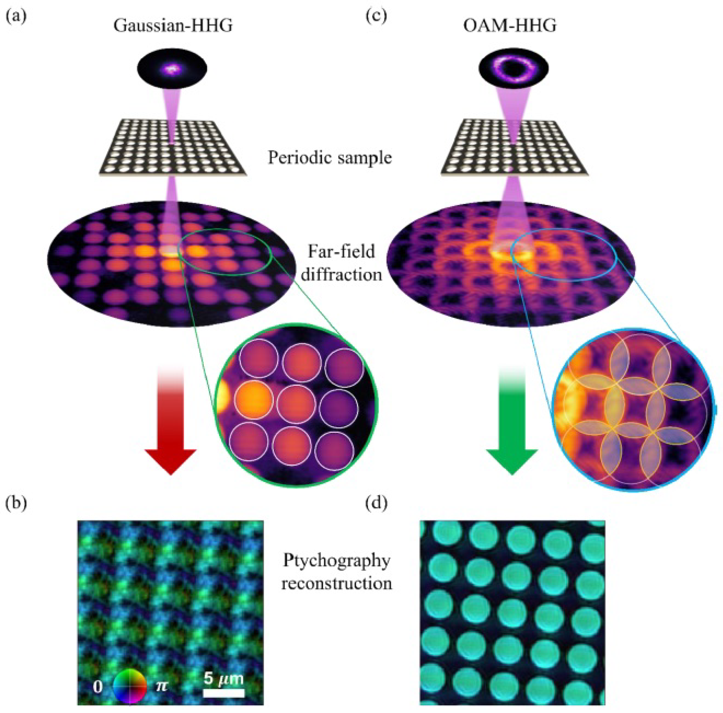
Rujia Li et al. propose an alternative structured phase modulation (ASPM) method for the effective reconstruction of a phase using SLM [188]. The same group has improvised their method in the same year and has modulated the complex wavefront with the vortex phase to serve as topological constraints. The spectrum intensities of the modulated wavefront recorded serve as the intensity constraints. The complex-amplitude object has been iteratively reconstructed using topological and intensity constraints without a priori knowledge. The stagnation problem in the reconstruction iterations is shown to be overcome with sufficient topological constraints [189]. Atypical schematic of the vortex phase modulation method is shown in Figure 18.

2.18. Ptychography

Ptychography is a contemporary computational method of microscopic imaging. It is a particular variant of coherent diffraction imaging (CDI) that is lensless, which makes use of reconstruction from multiple far-field diffraction patterns taken from illuminating small overlapping regions of the sample [190,191,192]. This method distinctly images clear objects without the hassles of staining or labeling. This versatile technique can be used with visible light, X-rays, extreme UV (EUV), and electrons. Vortices have been put to use in ptychography too. It has been demonstrated that multiplexed ptychographic CDI can be used as a high spatial resolution, phase-and-amplitude hyperspectral wavefront sensor by simultaneously characterizing an OAM beam together with its frequency-doubled second-harmonic beam. This approach is expected to be applicable not only to OAM beams but also to any other complex/structured light fields to characterize electron [193] and neutron vortex beams [194] as well as other matter waves [195]. There is also a research thesis on the application of a vortex beam in ptychography [196]. This has been motivated by the fact that vortex beams have a higher imaging quality in ptychography. Studies show that the topological charge and defocus of vortices also influence the reconstruction quality of the samples to a certain extent. Fourier ptychography (FP) microscopy is a novel computational spatial ptychography imaging technology developed in recent years. FP microscopy combines the advantages of large field of view, high resolution, and quantitative phase imaging, and hence has received extensive attention in the fields of optical microscopy, biomedicine, and life sciences. A high-resolution imaging algorithm based on FP has been proposed for moving target imaging by vortex electromagnetic forward-looking radar (VEMFLR) [187]. An FP imaging algorithm has been derived from a related imaging technology called ptychographic iterative engine (PIE) [190,197]. Ptychographic imaging of an isolated, near-diffraction-limited defect in an otherwise periodic sample using vortex high harmonic beams has been demonstrated by Wang et al. They have shown that the increase in reconstruction quality is enabled by OAM-HHG beams, especially the suppression of periodic artifacts in the reconstructions (inherent to ptychographic imaging of periodic structures). This enables the reliable location of nanoscale defects in otherwise highly periodic structures [198]. This can be seen in Figure 19. In this work, extreme UV light has been used.
In another work [199], using extreme ultraviolet OAM beams of different topological charge l, single-shot ptychography on a nanostructured object at a seeded free-electron laser, was performed. The vortices with different topological charges were generated with spiral zone plates, and the simultaneous propagation of three independent illumination modes was used in the study [200]. By controlling , it is reported that there is about 30% improvement in image resolution with respect to conventional Gaussian beam illumination. The ptychographic reconstructions were carried out employing the M-rPIE algorithm [201] implemented in the SciComPty software package [202]. A typical example is shown in Figure 20.
Successful demonstrations of off-axis X-ray vortex beam ptychography on weakly scattering objects have also been presented. The focused X-ray vortex beams are generated through partial illumination of the off-axis spiral zone plate (SZP). This configuration enhances edge contrasts, equivalent to dark-field imaging, making it suitable for imaging weak phase objects like optically thin biological specimens [203].

2.19. Encryption

In the world of soaring data traffic, the security of transmitted data becomes utmost priority [204]. As there is an evolution of newer encryption techniques, the hackers manage to find better methods too. In this scenario, optical singularities and structured beams appear to be promising candidates to enhance security because of their design and complexity. A novel information hiding method using a double-phase retrieval algorithm (DPRA) based on iterative nonlinear double random phase encoding (NDRPE) in the Fresnel domain under illumination of an optical vortex (OV) beam (for the first time) to encode the secret image into two phase-only masks (POMs) has been proposed. Compared with the classical LDRPE-based counterparts, the proposed algorithm has better performance on the convergence speed and improved security due to the use of an OV beam. The image is successfully decrypted only when illuminated by OV of correct topological charge as used in the encryption [205]. It has been shown that the use of phase singularities can integrate more system parameters as additional keys into one phase mask, thereby improving the security level of the cryptosystem. A multiple-image encryption scheme using the nonlinear iterative phase retrieval algorithm in the gyrator transform domain under the illumination of an optical vortex beam has been reported [206]. A cryptographic system that utilizes an optical vortex to implement double image encryption has been presented. The grayscale images have been encrypted individually using a DRPE phase mask incorporating two optical vortexes (OVs) in addition to a linear canonical transform (LCT) to ensure the heightened security of encryption. The encryption is performed digitally using a MATLAB platform, and decryption is performed optically [207]. Some of the phase masks are as shown in Figure 21.
There is a work featuring an XOR-operated optical vortex array enabled encryption of a binary image. Two-dimensional (XOR) logic operation using a light beam carrying an array of optical vortices has been implemented through a double-phase modulation of a laser beam [208]. An ultra-secure image encryption by tightly focusing perfect optical vortex (POV) beams with controllable annular intensity profiles and OAM states has been demonstrated. The idea was to employ an SLM to implement the Fourier transform of an ideal Bessel mode with both amplitude and phase modulations to generate radius-controllable POV in tightly focused beams [209]. A multi-user nonlinear optical cryptosystem using fractional-order vortex speckle (FOVS) patterns as security keys has been reported. FOVS are impossible to replicate, and the two private security keys that are obtained through polar decomposition enable the multi-user capability in the cryptosystem [210]. An array of optical vortices are shown to serve as a structured phase mask for encryption, aiding in noiseless decryption. The security of the encryption is enhanced as a result of the increased key length while employing lattices of optical vortices instead of a single OAM mode. The decoding has been implemented using a simple non-interferometric setup [211].
The same group has demonstrated binary image encryption with a QR code-encoded optical beam embedding an array of vortices. The approach offers ease of implementation, being a non-interferometric intensity recording-based encoding scheme [212]. The methodology to generate the designed vortex lattices array has been elaborated in [213]. A double secure encryption using asymmetric image encryption and vectorial light field encoding making use of a twisted nematic liquid crystal SLM and an array of structured phase masks has been reported [214] and a typical illustration is given in Figure 22.
A novel holographic encryption technique that combines OAM multiplexing with power-exponent helico-conical (PEHC) beams has been proposed. By precisely controlling the power exponent, normalization factor, and the topological charge, the phase and energy distribution of PEHC beams can be manipulated. The authors claim that integrating OAM multiplexing and PEHC beams into holographic encryption, the information capacity and robustness of information security can be enhanced [215]. One such result is given in Figure 23.
A novel method where four encryption keys multiplexed with a shared key in the form of a multichiral vortex beam has been reported. A coding method based on discrete displacement phase modulation has been proposed, enabling pattern separation in the spatial distribution of original information [216]. The schematic diagram of a chiral vortex holographic encryption is shown in Figure 24.

2.20. Deep Learning

Deep learning is a subset of machine learning that mimics human brain capabilities to learn from patterns and data. This is accomplished using deep neural networks that are multilayered to simulate the complex decision-making power of the human brain. Deep learning is the backbone of most of the artificial intelligence (AI) applications to date. It is known that vortex coronagraph is used to image celestial objects. Exoplanet imaging becomes more challenging because of the small angular separation and high contrast between planetary companions and their parent star. Hence, research has been conducted to combine the phase diversity provided by a vortex coronagraph with modern deep learning techniques to perform efficient focal-plane wavefront sensing (FPWFS) without losing observing time. The convolutional neural network (CNN), namely, EfficientNet-B4 has been employed to infer phase aberrations from simulated focal-plane images [217]. Images received from biomedical imaging, non-destructive testing, and computer-assisted surgery are diffuse images. To add to the problem, when light interacts with diffuse media, it leads to multiple scattering of the photons in the angular and spatial domain, thereby severely degrading the image reconstruction process.There is always a search for better imaging techniques. A novel method to image through diffuse media using multiple modes of vortex beams and a new deep learning network named “LGDiffNet”CNN architecture has been reported. The use of multiple modes of vortex beams instead of conventional Gaussian beams improves the imaging system’s capability and enhances the network’s reconstruction ability [218].
Finding the phase of conjugate optical vortices has always posed a problem. Ge Ding et al. proposed and demonstrated a CNN method to recover the helical phases of vortex beams (VBs). The interferograms obtained by interfering the VBs with a Gaussian spherical wave (GSW) provides the conjugate and initial phase information required [219]. A deep learning-based approach to simultaneously detect phase and polarization singularities of cylindrical vector vortex beams (CVVBs) with an accuracy of up to 99% has been reported. This detection method raises the possibility of optical information transmission using phase and polarization singularities as data carriers, thereby doubling the channel capacity [220]. A typical example of this kind of image transmission is shown in Figure 25.
Stokes vortex beams can also be detected using deep learning [221]. Deep learning also addresses the reduction in decoding accuracy of the optical communication system caused by atmospheric turbulence. Zhao et al. used the K-means clustering algorithm to construct a neural network to restore the degraded image of a single vortex beam obtained by segmentation. This can be extended to a vortex beam array, and the work shows that the intensity correlation coefficients of the 3 × 3 rectangular distribution of Laguerre–Gaussian beam arrays are increased to more than 0.99 after restoring from 1000 m of transmission in both varied and unknown turbulence intensities, alongside differing CCD signal-to-noise ratios [222].

3. Concluding Remarks

This is the first review paper on the use of optical phase singularities in computational optics. When we started writing this article, we realized that there are multiple groups working in this area, but most of them work in isolation. We hope that this review article will bring all of them together. This article reviews the status of research in this area in twenty different sections. We believe that we have covered most of the topics.

Author Contributions

Conceptualization, S.P.; writing—original draft preparation, S.D.; writing—review and editing, S.P. and K.K.; supervision, S.P.; funding acquisition, S.P. All authors have read and agreed to the published version of the manuscript.

Funding

This research was funded by SERB grant (CRG/2022/001267). K.K. acknowledges partial support from the Abdul Kalam Technology Innovation National Fellowship awarded by the Indian National Academy of Engineering.

Institutional Review Board Statement

Not applicable.

Data Availability Statement

Since this is a review article, the data underlying the the results presented in this paper are available with the original authors cited in the references. However, the data generated by us may be provided upon reasonable request.

Conflicts of Interest

The authors declare no conflicts of interest.

References

  1. Senthilkumaran, P. Singularities in Physics and Engineering; IOP Publishing: Bristol, UK, 2024. [Google Scholar]
  2. Allen, L.; Beijersbergen, M.W.; Spreeuw, R.; Woerdman, J. Orbital angular momentum of light and the transformation of Laguerre-Gaussian laser modes. Phys. Rev. A 1992, 45, 8185. [Google Scholar] [CrossRef] [PubMed]
  3. Coullet, P.; Gil, L.; Rocca, F. Optical vortices. Opt. Commun. 1989, 73, 403–408. [Google Scholar] [CrossRef]
  4. Zhan, Q. Cylindrical vector beams: From mathematical concepts to applications. Adv. Opt. Photonics 2009, 1, 1–57. [Google Scholar] [CrossRef]
  5. Ruchi; Senthilkumaran, P.; Pal, S.K. Phase singularities to polarization singularities. Int. J. Opt. 2020, 2020, 2812803. [Google Scholar] [CrossRef]
  6. Senthilkumaran, P.; Masajada, J.; Sato, S. Interferometry with vortices. Int. J. Opt. 2012, 2012, 517591. [Google Scholar] [CrossRef]
  7. Pachava, S.; Dharmavarapu, R.; Vijayakumar, A.; Jayakumar, S.; Manthalkar, A.; Dixit, A.; Viswanathan, N.K.; Srinivasan, B.; Bhattacharya, S. Generation and decomposition of scalar and vector modes carrying orbital angular momentum: A review. Opt. Eng. 2020, 59, 041205. [Google Scholar] [CrossRef]
  8. Porfirev, A.P.; Kuchmizhak, A.A.; Gurbatov, S.O.; Juodkazis, S.; Khonina, S.N.; Kulchin, Y.N. Phase singularities and optical vortices in photonics. Phys. Usp 2022, 192, 841–866. [Google Scholar] [CrossRef]
  9. Angelsky, O.; Bekshaev, A.Y.; Vasnetsov, M.; Zenkova, C.Y.; Maksimyak, P.; Zheng, J. Optical phase singularities: Physical nature, manifestations and applications. Front. Phys. 2022, 10, 1060787. [Google Scholar] [CrossRef]
  10. Khare, K.; Butola, M.; Rajora, S. Fourier Optics and Computational Imaging; Springer Nature: Berlin/Heidelberg, Germany, 2023. [Google Scholar]
  11. Lohmann, A.W.; Paris, D. Binary Fraunhofer holograms, generated by computer. Appl. Opt. 1967, 6, 1739–1748. [Google Scholar] [CrossRef] [PubMed]
  12. Kim, M.K. Principles and techniques of digital holographic microscopy. SPIE Rev. 2010, 1, 018005. [Google Scholar] [CrossRef]
  13. Gerchberg, R.W. A practical algorithm for the determination of plane from image and diffraction pictures. Optik 1972, 35, 237–246. [Google Scholar]
  14. Gu, B.; Yang, G. On the phase retrieval problem in optical and electronic microscopy. Acta Opt. Sin. 1981, 1, 517–522. [Google Scholar]
  15. Yang, G.Z.; Gu, B.Y. On the amplitude-phase retrieval problem in optical systems. Acta Opt. Sin. 1981, 30, 410–413. [Google Scholar] [CrossRef]
  16. Fienup, J.R. Reconstruction of an object from the modulus of its Fourier transform. Opt. Lett. 1978, 3, 27–29. [Google Scholar] [CrossRef] [PubMed]
  17. Collaro, A.; Franceschetti, G.; Palmieri, F.; Ferreiro, M.S. Phase unwrapping by means of genetic algorithms. J. Opt. Soc. Am. A 1998, 15, 407–418. [Google Scholar] [CrossRef]
  18. Quatieri, T.; Oppenheim, A. Iterative techniques for minimum phase signal reconstruction from phase or magnitude. IEEE Trans. Acoust. Speech Signal Process. 1981, 29, 1187–1193. [Google Scholar] [CrossRef]
  19. Butola, M.; Rajora, S.; Khare, K. Phase retrieval with complexity guidance. J. Opt. Soc. Am. A 2019, 36, 202–211. [Google Scholar] [CrossRef]
  20. Rai, M.R.; Vijayakumar, A.; Rosen, J. Non-linear adaptive three-dimensional imaging with interferenceless coded aperture correlation holography (I-COACH). Opt. Express 2018, 26, 18143–18154. [Google Scholar] [CrossRef]
  21. Fienup, J.R. Phase retrieval algorithms: A personal tour. Appl. Opt. 2012, 52, 45–56. [Google Scholar] [CrossRef] [PubMed]
  22. Guo, C.; Liu, S.; Sheridan, J.T. Iterative phase retrieval algorithms. I: Optimization. Appl. Opt. 2015, 54, 4698–4708. [Google Scholar] [CrossRef]
  23. Shechtman, Y.; Eldar, Y.C.; Cohen, O.; Chapman, H.N.; Miao, J.; Segev, M. Phase retrieval with application to optical imaging: A contemporary overview. IEEE Signal Process. Mag. 2015, 32, 87–109. [Google Scholar] [CrossRef]
  24. Guo, C.; Wei, C.; Tan, J.; Chen, K.; Liu, S.; Wu, Q.; Liu, Z. A review of iterative phase retrieval for measurement and encryption. Opt. Lasers Eng. 2017, 89, 2–12. [Google Scholar] [CrossRef]
  25. Himanshu, S.B.G.; Yadav, R.K.; Poply, V. Different Phase Retrieval Algorithms: A Review. Int. J. Future Gener. Commun. Netw. 2020, 13, 1978–1989. [Google Scholar]
  26. Leith, E.N.; Upatnieks, J. Wavefront reconstruction with diffused illumination and three-dimensional objects. J. Opt. Soc. Am. 1964, 54, 1295–1301. [Google Scholar] [CrossRef]
  27. Baranova, N.; Zel’dovich, B.Y.; Mamaev, A.; Pilipetski, N.; Shkunov, V. Speckle-inhomogeneous field wavefront dislocations. Pis’ ma Zh. Eks. Teor. Fiz 1981, 33, 206–210. [Google Scholar]
  28. Freund, I.; Shvartsman, N.; Freilikher, V. Optical dislocation networks in highly random media. Opt. Commun. 1993, 101, 247–264. [Google Scholar] [CrossRef]
  29. Shvartsman, N.; Freund, I. Vortices in random wave fields: Nearest neighbor anticorrelations. Phys. Rev. Lett. 1994, 72, 1008. [Google Scholar] [CrossRef] [PubMed]
  30. May, M.; Françon, M. Correlation and information processing using speckles. J. Opt. Soc. Am. 1976, 66, 1275–1282. [Google Scholar] [CrossRef]
  31. Takai, N.; Iwai, T.; Asakura, T. Correlation distance of dynamic speckles. Appl. Opt. 1983, 22, 170–177. [Google Scholar] [CrossRef] [PubMed]
  32. Lecompte, D.; Smits, A.; Bossuyt, S.; Sol, H.; Vantomme, J.; Van Hemelrijck, D.; Habraken, A. Quality assessment of speckle patterns for digital image correlation. Opt. Lasers Eng. 2006, 44, 1132–1145. [Google Scholar] [CrossRef]
  33. Dogariu, A.; Carminati, R. Electromagnetic field correlations in three-dimensional speckles. Phys. Rep. 2015, 559, 1–29. [Google Scholar] [CrossRef]
  34. Bräuer, R.; Wojak, U.; Wyrowski, F.; Bryngdahl, O. Digital diffusers for optical holography. Opt. Lett. 1991, 16, 1427–1429. [Google Scholar] [CrossRef]
  35. Bräuer, R.; Wyrowski, F.; Bryngdahl, O. Diffusers in digital holography. J. Opt. Soc. Am. A 1991, 8, 572–578. [Google Scholar] [CrossRef]
  36. Nakayama, Y.; Kato, M. Diffuser with pseudorandom phase sequence. J. Opt. Soc. Am. 1979, 69, 1367–1372. [Google Scholar] [CrossRef]
  37. Dallas, W. Deterministic diffusers for holography. Appl. Opt. 1973, 12, 1179–1187. [Google Scholar] [CrossRef] [PubMed]
  38. Hirsch, P.M.; Jordan, J.A., Jr.; Lesem, L.B. Method of Making an Object Dependent Diffuser. U.S. Patent 3,619,022, 9 November 1971. [Google Scholar]
  39. Wyrowski, F.; Bryngdahl, O. Iterative Fourier-transform algorithm applied to computer holography. J. Opt. Soc. Am. A 1988, 5, 1058–1065. [Google Scholar] [CrossRef]
  40. Fienup, J.; Wackerman, C. Phase-retrieval stagnation problems and solutions. J. Opt. Soc. Am. A 1986, 3, 1897–1907. [Google Scholar] [CrossRef]
  41. Aagedal, H.; Schmid, M.; Beth, T.; Teiwes, S.; Wyrowski, F. Theory of speckles in diffractive optics and its application to beam shaping. J. Mod. Opt. 1996, 43, 1409–1421. [Google Scholar] [CrossRef]
  42. Senthilkumaran, P.; Wyrowski, F. Phase synthesis in wave-optical engineering: Mapping-and diffuser-type approaches. J. Mod. Opt. 2002, 49, 1831–1850. [Google Scholar] [CrossRef]
  43. Senthilkumaran, P.; Wyrowski, F.; Schimmel, H. Vortex stagnation problem in iterative Fourier transform algorithms. Opt. Lasers Eng. 2005, 43, 43–56. [Google Scholar] [CrossRef]
  44. Ghiglia, D.C.; Mastin, G.A.; Romero, L.A. Cellular-automata method for phase unwrapping. J. Opt. Soc. Am. A 1987, 4, 267–280. [Google Scholar] [CrossRef]
  45. Goldstein, R.M.; Zebker, H.A.; Werner, C.L. Satellite radar interferometry: Two-dimensional phase unwrapping. Radio Sci. 1988, 23, 713–720. [Google Scholar] [CrossRef]
  46. Huntley, J.; Buckland, J. Characterization of sources of 2π phase discontinuity in speckle interferograms. J. Opt. Soc. Am. A 1995, 12, 1990–1996. [Google Scholar] [CrossRef]
  47. Ghiglia, D.C.; Pritt, M.D. Two-Dimensional Phase Unwrapping: Theory, Algorithms, and Software; John Wiley & Sons: Hoboken, NJ, USA, 1998. [Google Scholar]
  48. Aoki, T.; Sotomaru, T.; Ozawa, T.; Komiyama, T.; Miyamoto, Y.; Takeda, M. Two-dimensional phase unwrapping by direct elimination of rotational vector fields from phase gradients obtained by heterodyne techniques. Opt. Rev. 1998, 5, 374–379. [Google Scholar] [CrossRef]
  49. Bahl, M.; Senthilkumaran, P. Helmholtz Hodge decomposition of scalar optical fields. J. Opt. Soc. Am. A 2012, 29, 2421–2427. [Google Scholar] [CrossRef]
  50. Khare, K. Complex signal representation, Mandel’s theorem, and spiral phase quadrature transform. Appl. Opt. 2008, 47, E8–E12. [Google Scholar] [CrossRef]
  51. Mandel, L. Complex representation of optical fields in coherence theory. J. Opt. Soc. Am. A 1967, 57, 613–617. [Google Scholar] [CrossRef]
  52. Fienup, J.R. Phase retrieval algorithms: A comparison. Appl. Opt. 1982, 21, 2758–2769. [Google Scholar] [CrossRef]
  53. Paganin, D.; Nugent, K.A. Noninterferometric phase imaging with partially coherent light. Phys. Rev. Lett. 1998, 80, 2586. [Google Scholar] [CrossRef]
  54. Dorrer, C.; Zuegel, J. Optical testing using the transport-of-intensity equation. Opt. Express 2007, 15, 7165–7175. [Google Scholar] [CrossRef]
  55. Anand, A.; Pedrini, G.; Osten, W.; Almoro, P. Wavefront sensing with random amplitude mask and phase retrieval. Opt. Lett. 2007, 32, 1584–1586. [Google Scholar] [CrossRef] [PubMed]
  56. Almoro, P.; Pedrini, G.; Osten, W. Complete wavefront reconstruction using sequential intensity measurements of a volume speckle field. Appl. Opt. 2006, 45, 8596–8605. [Google Scholar] [CrossRef]
  57. Díaz-Doutón, F.; Pujol, J.; Arjona, M.; Luque, S.O. Curvature sensor for ocular wavefront measurement. Opt. Lett. 2006, 31, 2245–2247. [Google Scholar] [CrossRef]
  58. Sharma, M.K.; Gaur, C.; Senthilkumaran, P.; Khare, K. Phase imaging using spiral-phase diversity. Appl. Opt. 2015, 54, 3979–3985. [Google Scholar] [CrossRef]
  59. Echeverri-Chacón, S.; Restrepo, R.; Cuartas-Vélez, C.; Uribe-Patarroyo, N. Vortex-enhanced coherent-illumination phase diversity for phase retrieval in coherent imaging systems. Opt. Lett. 2016, 41, 1817–1820. [Google Scholar] [CrossRef]
  60. Scivier, M.; Fiddy, M. Phase ambiguities and the zeros of multidimensional band-limited functions. J. Opt. Soc. Am. A 1985, 2, 693–697. [Google Scholar] [CrossRef]
  61. Wackerman, C.; Yagle, A. Use of Fourier domain real-plane zeros to overcome a phase retrieval stagnation. J. Opt. Soc. Am. A 1991, 8, 1898–1904. [Google Scholar] [CrossRef]
  62. Wackerman, C.C.; Yagle, A.E. Phase retrieval and estimation with use of real-plane zeros. J. Opt. Soc. Am. A 1994, 11, 2016–2026. [Google Scholar] [CrossRef]
  63. Kularia, M.; Banerjee, M.; Khare, K. Twin-stagnation free phase retrieval with vortex phase illumination. J. Opt. Soc. Am. A 2024, 41, 2016–2026. [Google Scholar] [CrossRef] [PubMed]
  64. Cheng, M.; Guo, L.; Li, J.; Zhang, Y. Channel capacity of the OAM-based free-space optical communication links with Bessel–Gauss beams in turbulent ocean. IEEE Photonics J. 2016, 8, 7901411. [Google Scholar] [CrossRef]
  65. Zhang, Y.; Shan, L.; Li, Y.; Yu, L. Effects of moderate to strong turbulence on the Hankel-Bessel-Gaussian pulse beam with orbital angular momentum in the marine-atmosphere. Opt. Express 2017, 25, 33469–33479. [Google Scholar] [CrossRef]
  66. Li, Y.; Yu, L.; Zhang, Y. Influence of anisotropic turbulence on the orbital angular momentum modes of Hermite-Gaussian vortex beam in the ocean. Opt. Express 2017, 25, 12203–12215. [Google Scholar] [CrossRef] [PubMed]
  67. Rusch, L.A.; Rad, M.; Allahverdyan, K.; Fazal, I.; Bernier, E. Carrying data on the orbital angular momentum of light. IEEE Commun. Mag. 2018, 56, 219–224. [Google Scholar] [CrossRef]
  68. Willner, A.E.; Zhao, Z.; Ren, Y.; Li, L.; Xie, G.; Song, H.; Liu, C.; Zhang, R.; Bao, C.; Pang, K. Underwater optical communications using orbital angular momentum-based spatial division multiplexing. Opt. Commun. 2018, 408, 21–25. [Google Scholar] [CrossRef]
  69. Amhoud, E.M.; Ooi, B.S.; Alouini, M.S. A unified statistical model for atmospheric turbulence-induced fading in orbital angular momentum multiplexed FSO systems. IEEE Trans. Wirel. Commun. 2019, 19, 888–900. [Google Scholar] [CrossRef]
  70. Sawant, A.; Lee, I.; Jung, B.C.; Choi, E. Ultimate capacity analysis of orbital angular momentum channels. IEEE Wirel. Commun. 2020, 28, 90–96. [Google Scholar] [CrossRef]
  71. Huang, Y.; Zhang, B.; Gao, Z.; Zhao, G.; Duan, Z. Evolution behavior of Gaussian Schell-model vortex beams propagating through oceanic turbulence. Opt. Express 2014, 22, 17723–17734. [Google Scholar] [CrossRef]
  72. Yan, B.; Lu, Z.; Hu, J.; Xu, T.; Zhang, H.; Lin, W.; Yue, Y.; Liu, H.; Liu, B. Orbital angular momentum (OAM) carried by asymmetric vortex beams for wireless communications: Theory, experiment and current challenges. IEEE J. Sel. Top. Quantum Electron. 2020, 27, 7600310. [Google Scholar] [CrossRef]
  73. Köse, U.; Güraksin, G.E.; Deperlioğlu, Ö. Improving underwater image quality via vortex optimization algorithm. In Proceedings of the International Multidisciplinary Conference (IMUCO 2016), Antalya, Turkey, 10–13 October 2016; p. 327. [Google Scholar]
  74. Chang, H.; Yin, X.; Cui, X.; Chen, X.Z.; Su, Y.Z.; Ma, J.X.; Wang, Y.J.; Zhang, L.; Xin, X. Performance analysis of adaptive optics with a phase retrieval algorithm in orbital-angular-momentum-based oceanic turbulence links. Appl. Opt. 2019, 58, 6085–6090. [Google Scholar] [CrossRef] [PubMed]
  75. Yang, H.; Yan, Q.; Zhang, Y.; Hu, L. Received probability of perfect optical vortex in absorbent and weak turbulent seawater links. Appl. Opt. 2021, 60, 10772–10779. [Google Scholar] [CrossRef] [PubMed]
  76. Yan, Q.; Zhang, Y.; Yu, L.; Zhu, Y. Absorptive turbulent seawater and parameter optimization of perfect optical vortex for optical communication. J. Mar. Sci. Eng. 2022, 10, 1256. [Google Scholar] [CrossRef]
  77. Hefner, B.T.; Marston, P.L. An acoustical helicoidal wave transducer with applications for the alignment of ultrasonic and underwater systems. J. Acoust. Soc. Am. 1999, 106, 3313–3316. [Google Scholar] [CrossRef]
  78. Kelly, M.E.; Shi, C. Design and simulation of acoustic vortex wave arrays for long-range underwater communication. JASA Express Lett. 2023, 3, 076001. [Google Scholar] [CrossRef] [PubMed]
  79. Volke-Sepúlveda, K.; Santillán, A.O.; Boullosa, R.R. Transfer of angular momentum to matter from acoustical vortices in free space. Phys. Rev. Lett. 2008, 100, 024302. [Google Scholar] [CrossRef]
  80. Thidé, B.; Then, H.; Sjöholm, J.; Palmer, K.; Bergman, J.; Carozzi, T.; Istomin, Y.N.; Ibragimov, F.N.; Khamitova, R. Utilization of photon orbital angular momentum in the low-frequency radio domain. Phys. Rev. Lett. 2007, 99, 087701. [Google Scholar] [CrossRef]
  81. Edfors, O.; Johansson, A.J. Is orbital angular momentum (OAM) based radio communication an unexploited area? IEEE Trans. Antennas Propag. 2011, 60, 1126–1131. [Google Scholar] [CrossRef]
  82. Li, Z.; Zhang, Q.; Qu, F.; Wei, Y.; Tu, X.; Xu, J.; Xu, W.; Yang, L. High-Speed Underwater Acoustic Orbital Angular Momentum Communications. IEEE J. Ocean. Eng. 2024, 49, 1588–1604. [Google Scholar] [CrossRef]
  83. Das, A.T.; Rajesh, R.; Gopinath, P. Performance analysis of Sinh and Cosh Gaussian vortex beam in vertical underwater optical communication. Waves Random Complex Media 2024, 1–28. [Google Scholar] [CrossRef]
  84. Dorn, R.; Quabis, S.; Leuchs, G. Sharper focus for a radially polarized light beam. Phys. Rev. Lett. 2003, 91, 233901. [Google Scholar] [CrossRef]
  85. Vicidomini, G.; Bianchini, P.; Diaspro, A. STED super-resolved microscopy. Nat. Methods 2018, 15, 173–182. [Google Scholar] [CrossRef] [PubMed]
  86. Hecht, E. Optics; Pearson Education India: New Delhi, India, 2012. [Google Scholar]
  87. Fatemi, F.K.; Bashkansky, M. Focusing properties of high charge number vortex laser beams. Appl. Opt. 2007, 46, 7573–7578. [Google Scholar] [CrossRef] [PubMed]
  88. Born, M.; Wolf, E. Principles of Optics: Electromagnetic Theory of Propagation, Interference and Diffraction of Light; Elsevier: Amsterdam, The Netherlands, 2013. [Google Scholar]
  89. Mahajan, V.N. Optical Imaging and Aberrations: Ray Geometrical Optics; SPIE Press: Bellingham, WA, USA, 1998. [Google Scholar]
  90. Sheppard, C.; Matthews, H. Imaging in high-aperture optical systems. J. Opt. Soc. Am. A 1987, 4, 1354–1360. [Google Scholar] [CrossRef]
  91. Sheppard, C.J. Validity of the Debye approximation. Opt. Lett. 2000, 25, 1660–1662. [Google Scholar] [CrossRef]
  92. Stamnes, J.J. Waves in Focal Regions: Propagation, Diffraction and Focusing of Light, Sound and Water Waves; Routledge: London, UK, 2017. [Google Scholar]
  93. Wolf, E.; Li, Y. Conditions for the validity of the Debye integral representation of focused fields. Opt. Commun. 1981, 39, 205–210. [Google Scholar] [CrossRef]
  94. Richards, B.; Wolf, E. Electromagnetic diffraction in optical systems, II. Structure of the image field in an aplanatic system. Proc. R. Soc. Lond. Ser. A Math. Phys. Sci. 1959, 253, 358–379. [Google Scholar]
  95. Helseth, L. Optical vortices in focal regions. Opt. Commun. 2004, 229, 85–91. [Google Scholar] [CrossRef]
  96. Bokor, N.; Iketaki, Y.; Watanabe, T.; Fujii, M. Investigation of polarization effects for high-numerical-aperture first-order Laguerre-Gaussian beams by 2D scanning with a single fluorescent microbead. Opt. Express 2005, 13, 10440–10447. [Google Scholar] [CrossRef]
  97. Kant, R. An analytical solution of vector diffraction for focusing optical systems with Seidel aberrations: I. spherical aberration, curvature of field, and distortion. J. Mod. Opt. 1993, 40, 2293–2310. [Google Scholar] [CrossRef]
  98. Kant, R. An analytical method of vector diffraction for focusing optical systems with Seidel aberrations II: Astigmatism and coma. J. Mod. Opt. 1995, 42, 299–320. [Google Scholar] [CrossRef]
  99. Singh, R.K.; Senthilkumaran, P.; Singh, K. Focusing of a vortex carrying beam with Gaussian background by a lens in the presence of spherical aberration and defocusing. Opt. Lasers Eng. 2007, 45, 773–782. [Google Scholar] [CrossRef]
  100. Singh, R.K.; Senthilkumaran, P.; Singh, K. Influence of astigmatism and defocusing on the focusing of a singular beam. Opt. Commun. 2007, 270, 128–138. [Google Scholar] [CrossRef]
  101. Singh, R.K.; Senthilkumaran, P.; Singh, K. Effect of coma on the focusing of an apertured singular beam. Opt. Lasers Eng. 2007, 45, 488–494. [Google Scholar] [CrossRef]
  102. Singh, R.K.; Senthilkumaran, P.; Singh, K. Effect of primary spherical aberration on high-numerical-aperture focusing of a Laguerre-Gaussian beam. J. Opt. Soc. Am. A 2008, 25, 1307–1318. [Google Scholar] [CrossRef]
  103. Singh, R.K.; Senthilkumaran, P.; Singh, K. Focusing of linearly-, and circularly polarized Gaussian background vortex beams by a high numerical aperture system afflicted with third-order astigmatism. Opt. Commun. 2008, 281, 5939–5948. [Google Scholar] [CrossRef]
  104. Pal, S.K.; Singh, R.K.; Senthilkumaran, P. Effect of primary astigmatism on the tight focusing of ellipse field singularities. Opt. Laser Technol. 2024, 169, 110078. [Google Scholar] [CrossRef]
  105. Pal, S.K.; Singh, R.K.; Senthilkumaran, P. Influence of Primary Coma on the Tightly Focusing Characteristics of Circular Basis Hybrid Order Poincaré Sphere Beams. Photonics 2024, 11, 98. [Google Scholar] [CrossRef]
  106. Pal, S.K.; Somers, L.; Singh, R.K.; Senthilkumaran, P.; Arie, A. Focused polarization ellipse field singularities: Interaction of spin-orbital angular momentum and the formation of optical Möbius strips. Phys. Scr. 2023, 98, 055507. [Google Scholar] [CrossRef]
  107. Freund, I. Cones, spirals, and Möbius strips, in elliptically polarized light. Opt. Commun. 2005, 249, 7–22. [Google Scholar] [CrossRef]
  108. Bauer, T.; Banzer, P.; Karimi, E.; Orlov, S.; Rubano, A.; Marrucci, L.; Santamato, E.; Boyd, R.W.; Leuchs, G. Observation of optical polarization Möbius strips. Science 2015, 347, 964–966. [Google Scholar] [CrossRef] [PubMed]
  109. Zhao, Y.; Edgar, J.S.; Jeffries, G.D.; McGloin, D.; Chiu, D.T. Spin-to-orbital angular momentum conversion in a strongly focused optical beam. Phys. Rev. Lett. 2007, 99, 073901. [Google Scholar] [CrossRef] [PubMed]
  110. Bahl, M.; Senthilkumaran, P. Focal plane internal energy flows of singular beams in astigmatically aberrated low numerical aperture systems. J. Opt. Soc. Am. A 2014, 31, 2046–2054. [Google Scholar] [CrossRef]
  111. Bahl, M.; Singh, B.K.; Kumar, R.; Senthilkumaran, P. Internal energy flows of coma-affected singular beams in low-numerical-aperture systems. J. Opt. Soc. Am. A 2015, 32, 514–521. [Google Scholar] [CrossRef] [PubMed]
  112. Bahl, M.; Senthilkumaran, P. Energy circulations in singular beams diffracted through an isosceles right triangular aperture. Phys. Rev. A 2015, 92, 013831. [Google Scholar] [CrossRef]
  113. Sharma, M.K.; Joseph, J.; Senthilkumaran, P. Selective edge enhancement using anisotropic vortex filter. Appl. Opt. 2011, 50, 5279–5286. [Google Scholar] [CrossRef]
  114. Khonina, S.; Kotlyar, V.; Shinkaryev, M.; Soifer, V.; Uspleniev, G. The phase rotor filter. J. Mod. Opt. 1992, 39, 1147–1154. [Google Scholar] [CrossRef]
  115. Lohmann, A.W.; Mendlovic, D.; Zalevsky, Z. Fractional hilbert transform. Opt. Lett. 1996, 21, 281–283. [Google Scholar] [CrossRef]
  116. Davis, J.A.; McNamara, D.E.; Cottrell, D.M. Analysis of the fractional Hilbert transform. Appl. Opt. 1998, 37, 6911–6913. [Google Scholar] [CrossRef]
  117. Davis, J.A.; McNamara, D.E.; Cottrell, D.M.; Campos, J. Image processing with the radial Hilbert transform: Theory and experiments. Opt. Lett. 2000, 25, 99–101. [Google Scholar] [CrossRef]
  118. Pan, Y.; Jia, W.; Yu, J.; Dobson, K.; Zhou, C.; Wang, Y.; Poon, T.C. Edge extraction using a time-varying vortex beam in incoherent digital holography. Opt. Lett. 2014, 39, 4176–4179. [Google Scholar] [CrossRef]
  119. Sharma, M.K.; Joseph, J.; Senthilkumaran, P. Selective edge enhancement using shifted anisotropic vortex filter. J. Opt. 2013, 42, 1–7. [Google Scholar] [CrossRef]
  120. Zhang, B.; Chen, Z.; Sun, H.; Xia, J.; Ding, J. Vectorial optical vortex filtering for edge enhancement. J. Opt. 2016, 18, 035703. [Google Scholar] [CrossRef]
  121. Bhargava Ram, B.; Senthilkumaran, P.; Sharma, A. Polarization-based spatial filtering for directional and nondirectional edge enhancement using an S-waveplate. Appl. Opt. 2017, 56, 3171–3178. [Google Scholar] [CrossRef]
  122. Gu, Z.; Yin, D.; Nie, S.; Feng, S.; Xing, F.; Ma, J.; Yuan, C. Advances of image edge enhancement based on vortex filtering. Infrared Laser Eng. 2019, 48, 603015. [Google Scholar]
  123. Gao, Z.; Wang, Y.; Han, L.; Li, C.; Xin, X. Image edge enhancement technique using a novel optical vortex filtering. In Proceedings of the 2021 19th International Conference on Optical Communications and Networks (ICOCN), Qufu, China, 23–27 August 2021; IEEE: Piscataway, NJ, USA, 2021; pp. 1–3. [Google Scholar]
  124. Tan, W.; Bai, Y.; Huang, X.; Jiang, T.; Nan, S.; Fu, Q.; Zou, X.; Fu, X. Enhancing critical resolution of a ghost imaging system by using a vortex beam. Opt. Express 2022, 30, 14061–14072. [Google Scholar] [CrossRef] [PubMed]
  125. Li, L.; Ma, J.; Sun, D.; Tian, Z.; Cao, L.; Su, P. Amp-vortex edge-camera: A lensless multi-modality imaging system with edge enhancement. Opt. Express 2023, 31, 22519–22531. [Google Scholar] [CrossRef]
  126. Yu, X.; Wang, Z.; Cheng, X.; Zhao, L.; Li, X.; Sun, Y. Nonlinear edge enhancement imaging based on Laguerre–Gaussian superimposed vortex filters. Opt. Lett. 2024, 49, 482–485. [Google Scholar] [CrossRef]
  127. Rosen, J.; Brooker, G. Digital spatially incoherent Fresnel holography. Opt. Lett. 2007, 32, 912–914. [Google Scholar] [CrossRef] [PubMed]
  128. Rosen, J.; Brooker, G. Non-scanning motionless fluorescence three-dimensional holographic microscopy. Nat. Photonics 2008, 2, 190–195. [Google Scholar] [CrossRef]
  129. He, J.; Zhang, P.; Su, J.; Wang, J.; Tian, Y.; Hu, Y.; Ma, F. Edge enhancement in three-dimensional vortex imaging based on FINCH by Bessel-like spiral phase modulation. Opt. Express 2024, 32, 1438–1450. [Google Scholar] [CrossRef] [PubMed]
  130. Li, Y.; Wang, Y.; He, Y.; Zhou, L.; Li, Y.; He, W.; Gu, G.; Chen, Q. Short-wavelength-infrared upconversion edge enhancement imaging based on a Laguerre-Gaussian composite vortex filter. Opt. Express 2024, 32, 21696–21707. [Google Scholar] [CrossRef] [PubMed]
  131. Lin, D.; Tao, S. Generation of auto-focusing vortex beam via segment vortex phase for imaging edge-enhancement. Phys. Scr. 2024, 99, 055517. [Google Scholar] [CrossRef]
  132. Zangpo, J.; Kobayashi, H. Single-pixel edge enhancement of object via convolutional filtering with localized vortex phase. arXiv 2024, arXiv:2403.15014. [Google Scholar]
  133. Xu, D.; Zhang, W. Implementing the edge enhancement with vortex filter in both linear and nonlinear optics. Front. Phys. 2023, 11, 1276830. [Google Scholar] [CrossRef]
  134. Beresna, M.; Gecevičius, M.; Kazansky, P.G. Polarization sensitive elements fabricated by femtosecond laser nanostructuring of glass. Opt. Mater. Express 2011, 1, 783–795. [Google Scholar] [CrossRef]
  135. Slussarenko, S.; Murauski, A.; Du, T.; Chigrinov, V.; Marrucci, L.; Santamato, E. Tunable liquid crystal q-plates with arbitrary topological charge. Opt. Express 2011, 19, 4085–4090. [Google Scholar] [CrossRef]
  136. Marrucci, L. The q-plate and its future. J. Nanophotonics 2013, 7, 078598. [Google Scholar] [CrossRef]
  137. Khonina, S.; Porfirev, A.; Ustinov, A. Sudden autofocusing of superlinear chirp beams. J. Opt. 2018, 20, 025605. [Google Scholar] [CrossRef]
  138. Li, D.; Feng, S.; Nie, S.; Ma, J.; Yuan, C. Scalar and vectorial vortex filtering based on geometric phase modulation with a q-plate. J. Opt. 2019, 21, 065702. [Google Scholar] [CrossRef]
  139. Zangpo, J.; Kawabe, T.; Kobayashi, H. Edge-enhanced microscopy of complex objects using scalar and vectorial vortex filtering. Opt. Express 2023, 31, 38388–38399. [Google Scholar] [CrossRef] [PubMed]
  140. Segawa, S.; Kozawa, Y.; Sato, S. Demonstration of subtraction imaging in confocal microscopy with vector beams. Opt. Lett. 2014, 39, 4529–4532. [Google Scholar] [CrossRef] [PubMed]
  141. Rong, Z.; Kuang, C.; Fang, Y.; Zhao, G.; Xu, Y.; Liu, X. Super-resolution microscopy based on fluorescence emission difference of cylindrical vector beams. Opt. Commun. 2015, 354, 71–78. [Google Scholar] [CrossRef]
  142. Zhu, D.; Liu, W.; Zhang, Z.; Zheng, C.; Chen, Y.; Li, C.; Kuang, C.; Fan, J.; Xu, Y.; Liu, X.; et al. Enhancement of fluorescence emission difference microscopy using conjugated vortex phase modulation. J. Microsc. 2018, 272, 151–159. [Google Scholar] [CrossRef] [PubMed]
  143. Masajada, J.; Leniec, M.; Jankowska, E.; Thienpont, H.; Ottevaere, H.; Gomez, V. Deep microstructure topography characterization with optical vortex interferometer. Opt. Express 2008, 16, 19179–19191. [Google Scholar] [CrossRef] [PubMed]
  144. Masajada, J.; Leniec, M.; Augustyniak, I. Optical vortex scanning inside the Gaussian beam. J. Opt. 2011, 13, 035714. [Google Scholar] [CrossRef]
  145. Augustyniak, I.; Popiołek-Masajada, A.; Masajada, J.; Drobczyński, S. New scanning technique for the optical vortex microscope. Appl. Opt. 2012, 51, C117–C124. [Google Scholar] [CrossRef] [PubMed]
  146. Popiołek-Masajada, A.; Masajada, J.; Kurzynowski, P. Analytical model of the optical vortex scanning microscope with a simple phase object. Photonics 2017, 4, 38. [Google Scholar] [CrossRef]
  147. Sokolenko, B.; Shostka, N.; Karakchieva, O.; Poletaev, D.; Voytitsky, V.; Halilov, S.; Prisyazhniuk, A.; Ilyasova, A.; Kolosenko, E. Optical vortex phase determination for nanoscale imaging. J. Phys. Conf. Ser. 2018, 1062, 012004. [Google Scholar] [CrossRef]
  148. Ni, J.; Huang, C.; Zhou, L.M.; Gu, M.; Song, Q.; Kivshar, Y.; Qiu, C.W. Multidimensional phase singularities in nanophotonics. Science 2021, 374, eabj0039. [Google Scholar] [CrossRef] [PubMed]
  149. Singh, M.P.; Pandey, N.; Khare, K. High contrast computational imaging with vortex phase diversity. J. Phys. B At. Mol. Opt. Phys. 2024, 57, 225402. [Google Scholar] [CrossRef]
  150. Lee, H.; Kim, J.; Kim, H.H.; Kim, C.S.; Kim, J. Review on optical imaging techniques for multispectral analysis of nanomaterials. Nanotheranostics 2022, 6, 50. [Google Scholar] [CrossRef]
  151. Wang, W.; Qiao, Y.; Ishijima, R.; Yokozeki, T.; Honda, D.; Matsuda, A.; Hanson, S.G.; Takeda, M. Constellation of phase singularities in a specklelike pattern for optical vortex metrology applied to biological kinematic analysis. Opt. Express 2008, 16, 13908–13917. [Google Scholar] [CrossRef]
  152. Wang, W.; Yokozeki, T.; Ishijima, R.; Wada, A.; Miyamoto, Y.; Takeda, M.; Hanson, S.G. Optical vortex metrology for nanometric speckle displacement measurement. Opt. Express 2006, 14, 120–127. [Google Scholar] [CrossRef]
  153. Wang, W.; Dennis, M.R.; Ishijima, R.; Yokozeki, T.; Matsuda, A.; Hanson, S.G.; Takeda, M. Poincaré sphere representation for the anisotropy of phase singularities and its applications to optical vortex metrology for fluid mechanical analysis. Opt. Express 2007, 15, 11008–11019. [Google Scholar] [CrossRef]
  154. Takeda, M.; Wang, W.; Hanson, S.G.; Miyamoto, Y. Optical vortex metrology: Are phase singularities foes or friends in optical metrology? In Proceedings of the Eighth International Conference on Correlation Optics, Chernivsti, Ukraine, 11–14 September 2007; SPIE: Bellingham, WA, USA, 2008; Volume 7008, pp. 410–417. [Google Scholar]
  155. Wang, W.; Yokozeki, T.; Ishijima, R.; Takeda, M.; Hanson, S.G. Optical vortex metrology based on the core structures of phase singularities in Laguerre-Gauss transform of a speckle pattern. Opt. Express 2006, 14, 10195–10206. [Google Scholar] [CrossRef] [PubMed]
  156. Umapathy, K.; Nair, K.; Masse, S.; Krishnan, S.; Rogers, J.; Nash, M.P.; Nanthakumar, K. Phase mapping of cardiac fibrillation. Circ. Arrhythmia Electrophysiol. 2010, 3, 105–114. [Google Scholar] [CrossRef] [PubMed]
  157. Kuklik, P.; Zeemering, S.; Maesen, B.; Maessen, J.; Crijns, H.J.; Verheule, S.; Ganesan, A.N.; Schotten, U. Reconstruction of instantaneous phase of unipolar atrial contact electrogram using a concept of sinusoidal recomposition and Hilbert transform. IEEE Trans. Biomed. Eng. 2014, 62, 296–302. [Google Scholar] [CrossRef] [PubMed]
  158. Kuklik, P.; Zeemering, S.; van Hunnik, A.; Maesen, B.; Pison, L.; Lau, D.H.; Maessen, J.; Podziemski, P.; Meyer, C.; Schäffer, B.; et al. Identification of rotors during human atrial fibrillation using contact mapping and phase singularity detection: Technical considerations. IEEE Trans. Biomed. Eng. 2016, 64, 310–318. [Google Scholar]
  159. Roney, C.H.; Cantwell, C.D.; Bayer, J.D.; Qureshi, N.A.; Lim, P.B.; Tweedy, J.H.; Kanagaratnam, P.; Peters, N.S.; Vigmond, E.J.; Ng, F.S. Spatial resolution requirements for accurate identification of drivers of atrial fibrillation. Circ. Arrhythmia Electrophysiol. 2017, 10, e004899. [Google Scholar] [CrossRef] [PubMed]
  160. Bray, M.A.; Lin, S.F.; Aliev, R.R.; Roth, B.J.; Wikswo, J.P., Jr. Experimental and theoretical analysis of phase singularity dynamics in cardiac tissue. J. Cardiovasc. Electrophysiol. 2001, 12, 716–722. [Google Scholar] [CrossRef] [PubMed]
  161. Rantner, L.; Wieser, L.; Stühlinger, M.; Hintringer, F.; Tilg, B.; Fischer, G. Detection of phase singularities in triangular meshes. Methods Inf. Med. 2007, 46, 646–654. [Google Scholar] [PubMed]
  162. Tomii, N.; Yamazaki, M.; Arafune, T.; Honjo, H.; Shibata, N.; Sakuma, I. Detection algorithm of phase singularity using phase variance analysis for epicardial optical mapping data. IEEE Trans. Biomed. Eng. 2015, 63, 1795–1803. [Google Scholar] [CrossRef]
  163. Li, X.; Almeida, T.P.; Dastagir, N.; Guillem, M.S.; Salinet, J.; Chu, G.S.; Stafford, P.J.; Schlindwein, F.S.; Ng, G.A. Standardizing Single-Frame Phase Singularity Identification Algorithms and Parameters in Phase Mapping During Human Atrial Fibrillation. Front. Physiol. 2020, 11, 869. [Google Scholar] [CrossRef] [PubMed]
  164. Molavi Tabrizi, A.; Mesgarnejad, A.; Bazzi, M.; Luther, S.; Christoph, J.; Karma, A. Spatiotemporal organization of electromechanical phase singularities during high-frequency cardiac arrhythmias. Phys. Rev. X 2022, 12, 021052. [Google Scholar] [CrossRef]
  165. Masajada, J.; Dubik, B. Optical vortex generation by three plane wave interference. Opt. Commun. 2001, 198, 21–27. [Google Scholar] [CrossRef]
  166. Vyas, S.; Senthilkumaran, P. Interferometric optical vortex array generator. Appl. Opt. 2007, 46, 2893–2898. [Google Scholar] [CrossRef]
  167. Vyas, S.; Senthilkumaran, P. Vortex array generation by interference of spherical waves. Appl. Opt. 2007, 46, 7862–7867. [Google Scholar] [CrossRef] [PubMed]
  168. Masajada, J.; Popiołek-Masajada, A.; Wieliczka, D.M. The interferometric system using optical vortices as phase markers. Opt. Commun. 2002, 207, 85–93. [Google Scholar] [CrossRef]
  169. Popiołek-Masajada, A.; Borwińska, M. High sensitivity wave tilt measurements with optical vortex interferometer. In Proceedings of the Optical Sensing II, Strasbourg, France, 3–7 April 2006; SPIE: Bellingham, WA, USA, 2006; Volume 6189, pp. 53–59. [Google Scholar]
  170. Popiołek-Masajada, A.; Borwińska, M.; Dubik, B. Reconstruction of a plane wave’s tilt and orientation using an optical vortex interferometer. Opt. Eng. 2007, 46, 073604. [Google Scholar] [CrossRef]
  171. Frączek, W.; Mroczka, J. Optical vortices as phase markers to wave-front deformation measurement. Metrol. Meas. Syst. 2008, 15, 433–440. [Google Scholar]
  172. Woźniak, W.; Banach, M. Measurements of linearly birefringent media parameters using the optical vortex interferometer with the Wollaston compensator. J. Opt. Pure Appl. Opt. 2009, 11, 094024. [Google Scholar] [CrossRef]
  173. Shuang, Y.; Zhao, H.; Ji, W.; Cui, T.J.; Li, L. Programmable High-Order OAM-Carrying Beams for Direct-Modulation Wireless Communications. IEEE J. Emerg. Sel. Top. Circuits Syst. 2020, 10, 29–37. [Google Scholar] [CrossRef]
  174. Zhou, H.; Li, X.; Ullah, N.; Geng, G.; Li, J.; Li, X.; Wang, Y.; Huang, L. Single-shot phase retrieval based on anisotropic metasurface. Appl. Phys. Lett. 2022, 120, 161702. [Google Scholar] [CrossRef]
  175. Khare, K.; Lochab, P.; Senthilkumaran, P. Orbital Angular Momentum States of Light; IOP Publishing: Bristol, UK, 2020; pp. 2053–2563. [Google Scholar] [CrossRef]
  176. Lochab, P.; Senthilkumaran, P.; Khare, K. Robust laser beam engineering using polarization and angular momentum diversity. Opt. Express 2017, 25, 17524–17529. [Google Scholar] [CrossRef]
  177. Lochab, P.; Senthilkumaran, P.; Khare, K. Designer vector beams maintaining a robust intensity profile on propagation through turbulence. Phys. Rev. A 2018, 98, 023831. [Google Scholar] [CrossRef]
  178. Willner, A.E.; Song, H.; Zou, K.; Zhou, H.; Su, X. Orbital angular momentum beams for high-capacity communications. J. Light. Technol. 2022, 41, 1918–1933. [Google Scholar] [CrossRef]
  179. Sachdeva, S.; Kaur, S.; Arora, R.; Sindhwani, M.; Arora, K.; Cho, W.; Joshi, G.P.; Doo, I.C. Ultra-high capacity optical satellite communication system using PDM-256-QAM and optical angular momentum beams. Sensors 2023, 23, 786. [Google Scholar] [CrossRef]
  180. Zhang, H.; Li, Z.; Zhang, L.; Yang, H.; Sun, Q.; Zhang, D. Identification of multimodal vortex optical orbital angular momentum in multimode fiber speckle patterns. Opt. Commun. 2024, 573, 131009. [Google Scholar] [CrossRef]
  181. Zhang, H.; Zhu, J.; Lu, X.; Hu, Z.; Gao, J.; Liu, K.; Zhan, Q.; Cai, Y.; Zhao, C. Single-shot phase retrieval for randomly fluctuated and obstructed vortex beams. Sci. China Phys. Mech. Astron. 2024, 67, 244211. [Google Scholar] [CrossRef]
  182. Eshaghi, M.; Acevedo, C.H.; Batarseh, M.; Guzman-Sepulveda, J.R.; Dogariu, A. Phase memory of optical vortex beams. Sci. Rep. 2022, 12, 10428. [Google Scholar] [CrossRef]
  183. Liu, K.; Cheng, Y.; Yang, Z.; Wang, H.; Qin, Y.; Li, X. Orbital-angular-momentum-based electromagnetic vortex imaging. IEEE Antennas Wirel. Propag. Lett. 2014, 14, 711–714. [Google Scholar] [CrossRef]
  184. Liu, K.; Cheng, Y.; Li, X.; Gao, Y. Microwave-sensing technology using orbital angular momentum: Overview of its advantages. IEEE Veh. Technol. Mag. 2019, 14, 112–118. [Google Scholar] [CrossRef]
  185. Bu, X.; Zhang, Z.; Chen, L.; Liang, X.; Tang, H.; Wang, X. Implementation of vortex electromagnetic waves high-resolution synthetic aperture radar imaging. IEEE Antennas Wirel. Propag. Lett. 2018, 17, 764–767. [Google Scholar] [CrossRef]
  186. Liu, H.; Wang, Y.; Wang, J.; Liu, K.; Wang, H. Electromagnetic vortex enhanced imaging using fractional OAM beams. IEEE Antennas Wirel. Propag. Lett. 2021, 20, 948–952. [Google Scholar] [CrossRef]
  187. Liu, D.; Shi, H.; Yang, T.; Zhang, L. Autofocusing and imaging algorithm for moving target by vortex electromagnetic wave radar. Digit. Signal Process. 2023, 134, 103903. [Google Scholar] [CrossRef]
  188. Li, R.; Cao, L. Complex wavefront sensing based on alternative structured phase modulation. Appl. Opt. 2021, 60, A48–A53. [Google Scholar] [CrossRef]
  189. Li, R.; Cao, L. Complex wavefront sensing based on coherent diffraction imaging using vortex modulation. Sci. Rep. 2021, 11, 9019. [Google Scholar] [CrossRef]
  190. Rodenburg, J.M.; Faulkner, H.M. A phase retrieval algorithm for shifting illumination. Appl. Phys. Lett. 2004, 85, 4795–4797. [Google Scholar] [CrossRef]
  191. Li, P.; Maiden, A.M. Ten implementations of ptychography. J. Microsc. 2018, 269, 187–194. [Google Scholar] [CrossRef]
  192. Rodenburg, J.M. Ptychography and related diffractive imaging methods. Adv. Imaging Electron Phys. 2008, 150, 87–184. [Google Scholar]
  193. McMorran, B.J.; Agrawal, A.; Anderson, I.M.; Herzing, A.A.; Lezec, H.J.; McClelland, J.J.; Unguris, J. Electron vortex beams with high quanta of orbital angular momentum. Science 2011, 331, 192–195. [Google Scholar] [PubMed]
  194. Clark, C.W.; Barankov, R.; Huber, M.G.; Arif, M.; Cory, D.G.; Pushin, D.A. Controlling neutron orbital angular momentum. Nature 2015, 525, 504–506. [Google Scholar] [CrossRef] [PubMed]
  195. Esashi, Y.; Liao, C.T.; Wang, B.; Brooks, N.; Dorney, K.M.; Hernández-García, C.; Kapteyn, H.; Adams, D.; Murnane, M. Ptychographic amplitude and phase reconstruction of bichromatic vortex beams. Opt. Express 2018, 26, 34007–34015. [Google Scholar] [CrossRef] [PubMed]
  196. Chen, J. Research on the Application of Vortex Beam in Ptychography. Ph.D. Thesis, University of York, York, UK, 2020. [Google Scholar]
  197. Faulkner, H.M.L.; Rodenburg, J. Movable aperture lensless transmission microscopy: A novel phase retrieval algorithm. Phys. Rev. Lett. 2004, 93, 023903. [Google Scholar] [CrossRef] [PubMed]
  198. Wang, B.; Brooks, N.J.; Johnsen, P.; Jenkins, N.W.; Esashi, Y.; Binnie, I.; Tanksalvala, M.; Kapteyn, H.C.; Murnane, M.M. High-fidelity ptychographic imaging of highly periodic structures enabled by vortex high harmonic beams. Optica 2023, 10, 1245–1252. [Google Scholar] [CrossRef]
  199. Pancaldi, M.; Guzzi, F.; Bevis, C.S.; Manfredda, M.; Barolak, J.; Bonetti, S.; Bykova, I.; De Angelis, D.; De Ninno, G.; Fanciulli, M.; et al. High-resolution ptychographic imaging at a seeded free-electron laser source using OAM beams. Optica 2024, 11, 403–411. [Google Scholar] [CrossRef]
  200. Thibault, P.; Menzel, A. Reconstructing state mixtures from diffraction measurements. Nature 2013, 494, 68–71. [Google Scholar] [CrossRef] [PubMed]
  201. Guzzi, F.; Kourousias, G.; Billè, F.; Pugliese, R.; Gianoncelli, A.; Carrato, S. A modular software framework for the design and implementation of ptychography algorithms. PeerJ Comput. Sci. 2022, 8, e1036. [Google Scholar] [CrossRef]
  202. Guzzi, F.; Kourousias, G.; Gianoncelli, A.; Billè, F.; Carrato, S. A parameter refinement method for ptychography based on deep learning concepts. Condens. Matter 2021, 6, 36. [Google Scholar] [CrossRef]
  203. Lee, S.Y.; Park, E.; Kim, S.; Jo, E.; Lee, S.Y.; Choi, J.W.; Song, C. Off-Axis X-Ray Vortex Beam Ptychography. ACS Photonics 2024, 11, 3804–3810. [Google Scholar] [CrossRef]
  204. Nishchal, N.K. Optical Cryptosystems; IOP Publishing: Bristol, UK, 2019; pp. 2053–2563. [Google Scholar] [CrossRef]
  205. Wang, X.; Chen, W.; Chen, X. Optical image hiding using double-phase retrieval algorithm based on nonlinear cryptosystem under vortex beam illumination. J. Opt. 2015, 17, 035704. [Google Scholar] [CrossRef]
  206. Liansheng, S.; Bei, Z.; Xiaojuan, N.; Ailing, T. Optical multiple-image encryption based on the chaotic structured phase masks under the illumination of a vortex beam in the gyrator domain. Opt. Express 2016, 24, 499–515. [Google Scholar] [CrossRef]
  207. Singh, H.; Tirth, V.; Singh, R.K.; Algahtani, A.; Islam, S. Designing of an optical vortices phase mask and used in the frequency domain of linear canonical transform for double image encryption. Imaging Sci. J. 2020, 68, 288–304. [Google Scholar] [CrossRef]
  208. Kumar, P.; Nishchal, N.K.; Omatsu, T.; Rao, A.S. Optical vortex array for two-dimensional exclusive-OR operation. Appl. Phys. B 2022, 128, 98. [Google Scholar] [CrossRef]
  209. Yang, Q.; Xie, Z.; Zhang, M.; Ouyang, X.; Xu, Y.; Cao, Y.; Wang, S.; Zhu, L.; Li, X. Ultra-secure optical encryption based on tightly focused perfect optical vortex beams. Nanophotonics 2022, 11, 1063–1070. [Google Scholar] [CrossRef]
  210. Mandapati, V.C.; Vardhan, H.; Prabhakar, S.; Sakshi; Kumar, R.; Reddy, S.G.; Singh, R.P.; Singh, K. Multi-user nonlinear optical cryptosystem based on polar decomposition and fractional vortex speckle patterns. Photonics 2023, 10, 561. [Google Scholar] [CrossRef]
  211. Shikder, A.; Kumar, P.; Nishchal, N.K. Image Encryption by Structured Phase Encoding and Its Effectiveness in Turbulent Medium. IEEE Photonics Technol. Lett. 2023, 35, 128–131. [Google Scholar] [CrossRef]
  212. Shikder, A.; Rao, S.K.; Kumar, P.; Nishchal, N.K. Binary image encryption with a QR code-encoded optical beam having an array of vortices. J. Opt. Soc. Am. A 2024, 41, A73–A82. [Google Scholar] [CrossRef] [PubMed]
  213. Shikder, A.; Nishchal, N.K. Generation of optical vortex lattices by in-line phase modulation with partially coherent light. J. Opt. Soc. Am. A 2023, 40, 1231–1236. [Google Scholar] [CrossRef] [PubMed]
  214. Rao, S.K.; Nishchal, N.K.; AlFalou, A. Optical asymmetric image encryption using vectorial light field encoding. Opt. Commun. 2024, 554, 130097. [Google Scholar] [CrossRef]
  215. Wang, S.; Zhang, Z.; Zhou, Q.; Zhang, L.; Xu, B.; Wang, X. Holographic encryption with power-exponent helicon-conical optical vortices. Opt. Commun. 2024, 573, 131020. [Google Scholar] [CrossRef]
  216. Liu, R.; Li, Y.; Liu, Y.; Deng, D.; Wang, D.; Ding, S.; Wu, J. Multichiral Vortex Beam for High-Quality Information Encryption. ACS Photonics 2024, 11, 3105–3111. [Google Scholar] [CrossRef]
  217. Quesnel, M.; de Xivry, G.O.; Louppe, G.; Absil, O. A deep learning approach for focal-plane wavefront sensing using vortex phase diversity. Astron. Astrophys. 2022, 668, A36. [Google Scholar] [CrossRef]
  218. Balasubramaniam, G.M.; Biton, N.; Arnon, S. Imaging through diffuse media using multi-mode vortex beams and deep learning. Sci. Rep. 2022, 12, 1561. [Google Scholar]
  219. Ding, G.; Xiong, W.; Wang, P.; Huang, Z.; He, Y.; Liu, J.; Li, Y.; Fan, D.; Chen, S. Spatial phase retrieval of vortex beam using convolutional neural network. J. Opt. 2022, 24, 025701. [Google Scholar] [CrossRef]
  220. Feng, F.; Hu, J.; Wang, Y.; Guo, Z.; Li, N.; Zhao, B.; Yuan, X.; Somekh, M. Deep-learning enabled simultaneous detection of phase and polarization singularities of CVVBs and its application to image transmission. Opt. Laser Technol. 2024, 168, 109890. [Google Scholar] [CrossRef]
  221. Arora, G.; Butola, A.; Rajput, R.; Agarwal, R.; Agarwal, K.; Horsch, A.; Prasad, D.K.; Senthilkumaran, P. Taxonomy of hybridly polarized Stokes vortex beams. Opt. Express 2024, 32, 7404–7416. [Google Scholar] [CrossRef] [PubMed]
  222. Zhao, J.; Wei, H.; Du, Q.; Fu, Y.; Zhou, H. Degraded image restoration of vortex beam array based on deep learning. Phys. Scr. 2024, 99, 065537. [Google Scholar] [CrossRef]
Figure 1. (a) Intensity object for the CGH. (b) Numerically simulated reconstructed object from the CGH that is phase-randomized. Phase randomization increases the redundancy at the cost of speckles. Therefore, diffusers that improve the redundancy without introducing speckles are synthesized by iterative procedures.
Photonics 12 00096 g001
Figure 2. (a) Schematic setup for the reconstruction of CGH and (b) phase retrieval setup. In CGH, the reconstructed object that appears at the location C is an intensity object. To have redundancy in CGH, the intensity object at C is provided random phase, and the required complex field at the hologram plane is computed through IFTA. With the computed field, CGH is made. However, in (b), for the measured intensity in the detection plane D, a random phase is added as an initial guess, and the unknown phase that is received by the lens is computed (phase retrieved) through IFTA.
Photonics 12 00096 g002
Figure 3. Simulateddata for phase imaging using spiral phase diversity: (a,b) Fourier intensity data corresponding to “boat” object for plane wave and vortex illumination, (c) reconstruction of “boat” object, (d,e) Fourier intensity data corresponding to aspheric phase object for plane wave and vortex illumination, and (f) reconstruction of aspheric phase.
Photonics 12 00096 g003
Figure 4. Illustration of vortex illumination-based phase retrieval for “A” phase object using HIO algorithm. (a) Phase retrieval using HIO method where Fourier magnitude data are recorded with plane wave illumination. The phase recovery clearly shows twin stagnation. (b) Phase retrieval using HIO method where Fourier magnitude data are recorded with charge 1 vortex illumination. The phase recovery does not show any twin stagnation. (c) Phase reconstruction after subtracting out the extra vortex phase in (b). The circular region shows the support window used.
Photonics 12 00096 g004
Figure 5. A rawand improved underwater image using a vortex optimization algorithm. Reprinted with permission from the authors of [73].
Photonics 12 00096 g005
Figure 6. Mode purity as a function of the number of iterations for GSA and HIOA: (a) intensity distribution of the distorted signal beam before compensation; (bd) intensity distributions of the corrected signal beam with HIOA-based AO compensation in the cases of 20, 50, and 100 iterations, respectively; and (e) intensity distribution in the case of 100 iterations with GSA-based AO compensation. Reprinted with permission from [74] © Optical Society of America.
Photonics 12 00096 g006
Figure 7. HHD of a random vortex field added to a diverging spherical beam: (a) transverse phase profile. (b) phase gradient field lines of the beam superimposed on the phase profile, (c) flow lines of the solenoidal component of the Hodge decomposed field, and (d) irrotational component with diverging field lines. This is the vortex free field. Reprinted with permission from [49] © Optical Society of America.
Photonics 12 00096 g007
Figure 8. The edge enhancement reconstructions from the holograms by using vortex-BP (Spiral) and amp-vortex BP (LG, Bessel, Airy, and Sinc). The contrast C and intersecting lines are shown in the results. Reprinted with permission from [125] © Optica Publishing Group.
Photonics 12 00096 g008
Figure 9. Simulated results of an input Chinese dragon pattern shown in (a). The outputs shown in figures (bd) correspond to on-axis vortex filtering, off-axis vortex filtering, and polychromatic filtering, respectively. (c1d2) are two orthogonal polarized components of (c,d). Insets on the upper-right corner of each figure of (c1d2) illustrate the polarization direction of the analyzer. Reprinted with permission from [120] Copyright IOP publishing.
Photonics 12 00096 g009
Figure 10. Experimental result of the enhancement of an onion cell, which is a complex phase amplitude object (PAO) (a) without the Q-plate, (b) VVF image, (c) SVF image, and (d,e) surface plot of the phase edge of a wrapped portion (b,c). Reprinted with permission from [139] © Optica Publishing Group.
Photonics 12 00096 g010
Figure 11. Resolution enhancement experimental results. (AC) Confocal image, cFED image (r = 0.65), FED image (r = 0.65) of nanoparticles. (D,E) Intensity profiles of the dashed and solid white lines in (AC), respectively. All scales are the same as (A). Pixel size of 20 nm and dwell time of 6 μ s. (FH) Confocal image, cFED image (r = 0.6), FED image (r = 0.65) of microtubules. (I) FRC (Fourier ring correlation) of (FH). Note: r is a subtraction factor. Reprinted with permission from [142] Copyright: John Wiley & Sons, Inc.
Photonics 12 00096 g011
Figure 12. Vortex beams carrying phase singularities in nanophotonics. (A) Schematic illustration of vortex beams with helical wavefronts and unlimited topological charge. (B) Metasurfaces with a geometric phase provide phase singularities for generating vortex beams. (C) Vortex beams extracted in unidirectional WGM microcavities. (D) Phase singularities in momentum space generated by photonic crystal slabs. (E) Planar Archimedean nanostructures’ excited phase singularities in spatiotemporal domain. (F) On-chip discrimination of OAM beams by metallic gratings. (G) Nanoring slits for both SAM and OAM multiplexing of broadband light. (H) Photocurrent measurements for discriminating OAM of vortex beams. (I) Transmission of OAM beams in on-chip waveguides. From [148]. Reprinted with permission from AAAS.
Photonics 12 00096 g012
Figure 13. Illustration of vortex diversity incoherent imaging: (a) test object and blurred versions of the test object with (b) open aperture and (c) vortex aperture and (d) reconstructed image using (b,c) as data and generalized Wiener filter. The insets in (b,c) show blurring point spread functions (PSFs), and the inset in (d) shows effective computational PSF due to generalized Wiener filter processing. The reconstruction (d) shows significant contrast enhancement with respect to the diffraction-limited open aperture image in (b).
Photonics 12 00096 g013
Figure 14. The trajectory of the pseudo phase singularities inside the fugu’s body at different instants of time (a) t = 0.067 s, (b) t = 0.699 s, (c) t =1.665 s, and (d) t = 3.33 s. The locations for the positive and negative pseudophase singularities have been indicated by red and green points, respectively. Reprinted with permission from [151] © Optical Society of America.
Photonics 12 00096 g014
Figure 15. Recorded images (a,b) of the floating tea leaves on the water surface at different instants of time separated by 8 ms and the corresponding L–G signals (c,d) with positive and negative pseudo phase singularities indicated by red and green dots. Reprinted with permission from the authors of [154].
Photonics 12 00096 g015
Figure 16. The experimental results for phase-only object. (a) Target phase map. (b) The single-shot captured triple images via a metasurface. (c) The reconstructed intensity image based on the TTIE algorithm. (d) The reconstructed phase image based on the TTIE algorithm. (e) The second target phase map. The phase values are marked, unit: rad. (f) The second single-shot captured triple images via a metasurface. (g) The reconstructed intensity picture based on the TTIE algorithm. (h) The reconstructed phase image based on the TTIE algorithm. Reprinted from [174] with the permission of AIP Publishing.
Photonics 12 00096 g016
Figure 17. OAM multiplexing transmission principle based on multimode fiber. Reprinted from [180], Copyright (2024), with permission from Elsevier.
Photonics 12 00096 g017
Figure 18. Schematic of the vortex modulation method. (a) Phase and amplitude of the complex-amplitude object and its Fourier spectrum, which are shown in grayscale images with yellow hue; (b) vortex phase with topological charge l; (c) the complex-amplitude object modulated with the vortex phase and its Fourier spectrum with topological modulation. Reprinted with permission from [189] copyright Nature.
Photonics 12 00096 g018
Figure 19. Robust and reliable ptychographic imaging of highly periodic structures. (a) Schematic showing HHG ptychographic imaging of a periodic structure using conventional Gaussian–HHG illumination. The resulting diffraction orders are isolated (see zoomed-in green circle), where the white circles indicate the edges of each diffraction order. This leads to a complete loss of the relative phase information between the orders in the far-field diffraction, which subsequently leads to the failure of the ptychographic reconstruction in (b). (c) OAM-HHG illumination intrinsically has a larger source divergence and a ring-shaped intensity profile to support the overlap and interference between diffraction orders (see zoomed-in blue circle), in which the yellow circles indicate the edges of each diffraction order. This interference converts the relative phase between the diffraction orders into measurable intensity modulation, enabling fast and robust ptychographic reconstruction of the 2D periodic structure in (d). In (b,d), the complex-valued amplitude and phase are plotted as brightness and hue, respectively. Reprinted with permission from [198] © Optica Publishing Group.
Photonics 12 00096 g019
Figure 20. (ag) Ptychographic reconstructions of the Siemens star for = 0, ±1, ±2, and ±3. For each panel, the main illumination amplitude, the main illumination phase, and the object amplitude are shown. Reprinted with permission from [199] © Optica Publishing Group.
Photonics 12 00096 g020
Figure 21. (ad) is phase representation of radial Hilbert mask with the topological charge l = 10, 14, 17, and 20. (e) represents the phase pattern of plane of phase with some specific parameters (given in [207]) and (fi) are sum of phase pattern of RHT and plane of phase (a + e = f, b + e = g, c + e = h and d + e = i). Reprinted from [207] with permission from Taylor and Francis Ltd.
Photonics 12 00096 g021
Figure 22. Simulation results: (a) plaintext, (b) first encryption key, (c) second encryption key, (d) first decryption key, (e) second decryption key, (f) PVD (g) I(00), (h) I(450), (i) I(900), (j) I(1350), (k) Stokes’ parameter S1 (final decryption key), (l) Stokes’ parameter S2 (final encrypted image), and (m) retrieved image obtained after applying all correct keys. Reprinted from [214], Copyright (2024), with permission from Elsevier.
Photonics 12 00096 g022
Figure 23. Simulation and experimental reconstruction results of the T-n-encrypted OAM multiplexed holography. (a) Schematic diagram of the hologram design process based on PEHC-OAM selectivity. (be) Simulation reconstruction results. (b1e1) Experimental reconstruction results. Reprinted from [215], Copyright (2024), with permission from Elsevier.
Photonics 12 00096 g023
Figure 24. Schematic diagram of a chiral vortex holographic encryption. Reprinted with permission from [216] Copyright 2024 American Chemical Society.
Photonics 12 00096 g024
Figure 25. (a) The coding rule between grayscale values of image pixels and both the l and m recombination of CVVBs; (b) an 8-bit grayscale cat image transmission application. Reprinted from [220], Copyright (2024), with permission from Elsevier.
Photonics 12 00096 g025
Disclaimer/Publisher’s Note: The statements, opinions and data contained in all publications are solely those of the individual author(s) and contributor(s) and not of MDPI and/or the editor(s). MDPI and/or the editor(s) disclaim responsibility for any injury to people or property resulting from any ideas, methods, instructions or products referred to in the content.

