Article

Realization of the Compact Magneto-Optical Trap Based on Single Laser with Frequency Modulation

The Key Laboratory of Quantum Precision Measurement of Zhejiang Province, School of Physics, Zhejiang University of Technology, Hangzhou 310023, China
*
Author to whom correspondence should be addressed.
Photonics 2025, 12(2), 98; https://doi.org/10.3390/photonics12020098
Submission received: 10 December 2024 / Revised: 18 January 2025 / Accepted: 21 January 2025 / Published: 23 January 2025

Abstract

:
In cold atom physics, the complexity of traditional magneto-optical trap system limits the use of their associated instruments for field applications in atomic physics, such as gravity mapping, space navigation and deep space exploration. This study introduces a novel compact MOT design that addresses these issues by simplifying the structure and reducing the size. The height of the unit is 0.7 m, the volume is 6.3 × 10 2 m 3 and the mass is 11.32 kg. The new design utilizes a single laser to generate the two different frequencies needed for laser cooling by internally splitting the beam, shifting the frequency and then combining them, effectively controlling both the cooling and repumping beams. The compact vacuum chamber optical path, in conjunction with the magnetic field, facilitates the capture of 87Rb atoms in an ultra-high vacuum environment. Experimental results demonstrate an atom loading rate of up to 1.79 × 10 7 87Rb atoms per second, confirming the system’s effectiveness in capturing and cooling 87Rb atoms. This design provides a flexible and portable solution, offering valuable insights for the advancement of compact MOT and its applications in cold atom physics.

1. Introduction

Laser cooling and trapping of atoms [1,2,3,4] have opened a promising new field, enabling the cooling of atomic gases to near absolute zero for the study and exploration of quantum effects. The rapid advancement of laser cooling technology allows us to prepare cold atom clouds more conveniently, which is important for the development of cold atom physics and the its applications. Cold atoms have the advantages of low velocity, increased de Broglie wavelength, stable distribution, high spectral resolution, and pronounced quantum effects. These characteristics make cold atoms highly suitable for precision measurements, such as cold atom clocks [5,6,7,8,9,10], gravimeters [11,12,13,14,15], gravity gradiometers [16,17,18], and atom-interferometer gyroscopes [19,20,21]. Additionally, laser cooling and trapping of atoms are essential for studying various scenes, atomic frequency standards [22,23], ultracold collisions [24,25,26,27], and quantum mechanical effects [28,29]. Among these methods, the magneto-optical trap (MOT) technique [30] is particularly significant. It can provide the alkali metal Rb atomic sources needed for cold atom experiments.
Currently, the development of MOT technology focuses on miniaturization and new laser configurations. The Tianjin Institute of Maritime Instrumentation designed the structure and parameters of a MOT vacuum system, including the selection and design of key components such as vacuum pumps, vacuum chamber structures, and optical windows, resulting in a compact and practical ultra-high vacuum system, through the design of a differential tube, the overall height of the unit is approximately 1 m, the vacuum degree of the 2DMOT is controlled at 10 6 Pa, and the limit vacuum of the 3D-MOT reaches 10 8 Pa [31]. A research group from the school of physics and astronomy at the university of Birmingham developed a deployable MOT, and the system enclosure containing the MOT itself had an outer radius of 60 ± 0.1 mm at its widest point and a length of 890 ± 5 mm. The system generated, on average, clouds of ( 3.0 ± 0.1 ) × 10 5 87Rb atoms [32]. The team of Shanxi university simplified the MOT structure by using a large-aperture single laser beam combined with multiple mirrors. They also replaced the coils with permanent magnets to provide the required gradient magnetic field, enhancing the portability of the cold atom trapping device. This resulted in the development of a miniaturized MOT structure. The vacuum system of this structure has a length of 250 mm and a width of 190 mm, and experiments have shown that the size of the trapped 87Rb atoms atom group is about 1.5 mm and the number of cold atoms is about 1.7 × 10 7 [33]. In addition, for reliability and miniaturization, instead of the standard, six-beam MOT, a tetrahedral MOT was realized with four beams [34]. A pyramid MOT (PMOT) was demonstrated with a single beam incident on a corner of four mirrors [35], and integrated PMOT arrays were realized by etching pyramids into a silicon wafer [36]. The grating MOT (GMOT) of J. Lee’s research group requires only one beam and three planar diffraction gratings to form a cloud of cold atoms above the plane of the diffractors [37]. A mirror MOT of Masaharu Hyodo’s research group that exploits a hexapole-compensated magnetic field was developed and used in the experimental surface trapping of neutral atoms. In their experiment, the current-carrying wires were made of oxygen-free copper and fabricated to be approximately 28 mm long with cross sections of 1 × 1 and 1 × 2 mm2 for I 1 and I 2 , respectively. They were installed 1 mm apart edge-to-edge in an ultrahigh-vacuum chamber. A 0.5 mm thick, 25 mm diameter total reflection mirror covered the three wires to form a mirror-MOT configuration. In their mirror-MOT apparatus, approximately 7 × 10 7  87Rb atoms were captured from a background Rb pressure of about 5 × 10 10 Torr with a loading time constant of 1.3 s, it was shown that the mirror-MOT captured distant atoms more efficiently than a conventional one [38]. Recently, ColdQuanta introduced a stand-alone, compact, ultra-high vacuum (UHV) trapped atom system called the miniMOT V2. Overall, the dimensions of the unit are 149 × 119 × 298 mm and it weighs 3.3 kg. Equipped with standard thin-walled UHV glass cell, integrated ion pump, electronic drivers for the atom dispenser, and magnet coil assemblies, the miniMOT V2 enables the creation of Rb or Cs MOTs at the touch of a button; when paired with miniMOT Package and MOT Coils, users can align all laser beams entering the UHV glass cell and obtain precise control of magnetic fields for easy and controllable MOT generation of up to 10 8 cold atoms [39].
However, the common MOT schemes mentioned above require two or more lasers, resulting in complex structures, high costs, low integration, large size, and poor portability. To address these issues, this paper designs a novel frequency-locked optical path for the MOT, which uses only one laser to produce two frequencies of laser beams needed for laser cooling, effectively controlling both the cooling and repumping beams. Based on the principles of laser cooling and trapping, this paper designs and elaborates on the optical path and vacuum chamber of the MOT system. The performance parameters of the compact MOT system in this study were measured, and the system achieved a loading rate of up to 1.79 × 10 7 87Rb atoms per second. This study offers a new approach for developing compact MOT systems.

2. Experimentation

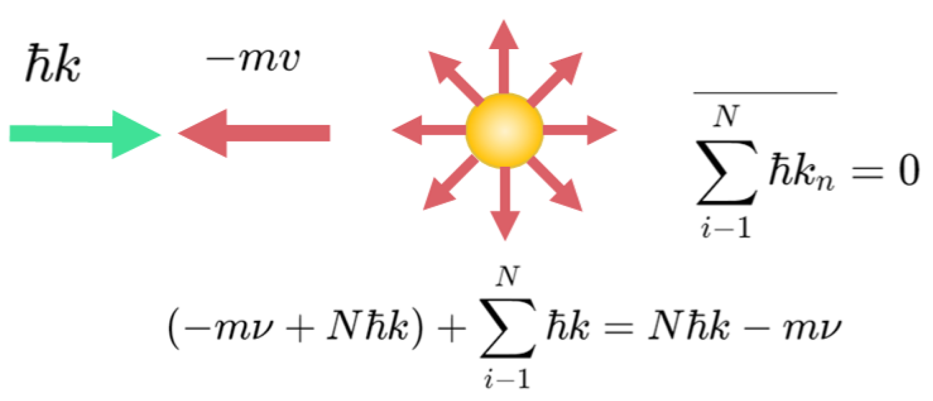
2.1. Experimental Principle

Traditional cooling methods reach temperatures of microkelvin ( μ K) [40,41]. Laser cooling, however, can reduce atomic temperatures to the nanokelvin nK by conserving energy and momentum during radiation absorption and emission [1,42,43]. Measurements have shown temperatures below the Doppler limit, indicating that atomic multi-level structures and the polarization of beams are crucial for cooling. The most commonly used method of laser cooling is Doppler cooling [44,45], whose physical principle mechanism is shown in Figure 1. For a moving atom, we just need to irradiate the atom by using a negatively detuned planar laser beam in the opposite direction of the atom’s motion, the atom will be decelerated and the atom will be subjected to the momentum of the photon during one absorption–radiation process, and the momentum will be reduced by k and the velocity will be reduced by k / m , after N times. The total momentum decreases by N k , and the velocity decreases by N k / m . For the 87Rb used in our experiments, the spontaneous radiation in the presence of a resonant beam is up to 10 6 10 8 times per second. Therefore, in principle, for an atom with an initial velocity of 1000 m/s, it takes only 4 ms to slow down to zero, but this cannot go indefinitely low, and there is a limit v D . When the speed of the atom is lowered, the above resonance condition can no longer be satisfied, and the deceleration effect is weaker or even stops. At very low velocities, the resonance condition implies that the frequency of the light wave is very close to the frequency of atoms since the narrowest width of the jump spectral line of the atoms is the natural width determined by the atomic energy level lifetimes. The method of Doppler cooling cannot ultimately remove the energy of the thermal motion that corresponds to the natural half-width, which is:
k B T D = 1 2 M v D 2 = 1 2 Γ v .
This gives the limited temperature for Doppler cooling:
T D = Γ v / 2 k B ,
where Γ v is the natural linewidth of the atomic transition, k B is the Boltzmann constant, and is the reduced Planck constant. For Rb, the Γ v is approximately 6.07 MHz. Substituting these values, we obtain the Doppler cooling limit for Rb atoms is approximately 144 μ K.
However, in reality, there are Doppler shifts and optical pumping effects in the process of photons cooling moving atoms. The so-called Doppler shift refers to the slowing down of the atoms while there is a Doppler shift due to the Doppler effect, and this shift may cause the frequency of the photon to differ too much from the resonance frequency of the atom, which causes the photon to cease to be absorbed by the atom, and no longer produces a slowing down effect on the atom. For this effect, the experimental compensation of the atomic Doppler shift is usually achieved by using the Zeeman effect [46] or the Stark effect [47] of atoms in a magnetic or electric field. Since the first-order Stark effect is zero in the ground state of the alkali metal atom 87Rb, the Zeeman effect is used. For an atom decelerating uniformly along the z-axis, the required magnetic field shift is given by,
B ( z ) = B 0 ( 0 ) 1 2 a z / ν 0 2 ,
where B 0 ( 0 ) is the value of the magnetic field at the deceleration.
In fact, the atom is not just a simple two-energy level system. This ultra-fine energy level splitting and each ultra-fine energy level also exists in many Zeeman sub-levels. Even if the magnetic field is zero, the interaction of the light field and the atom can cause the ultra-fine structure of the energy level to merge with the lifting of different Zeeman energy level splitting. Therefore, after absorbing the decelerated photon, the atom is very likely to fall into other non-resonant energy levels in the process of returning to the ground state from the excited state, which makes the atomic cooling process terminate; this process is the so-called optical pumping effect, and the experiment is usually based on the dipole jump rule of atoms to choose the appropriate jump energy level and the direction of the polarization of the cooling laser to overcome, but taking into account that it is very difficult to obtain the ideal circularly polarized laser beam, it is necessary to attach an additional repumping beam with a frequency resonant with another ground-state hyperfine energy level instead, also called a repumping beam. To facilitate the cycling process of atomic absorption of cooling beams and spontaneous emission, the beam repumping effect [48] is essential. In practical MOTs, along with the six cooling beams and Helmholtz coils [49], a repumping beam is usually required to mitigate the beam-pumping effect. This allows the cooling process to repeat multiple times and achieve effective cooling.
The typical structure of 3D-MOT is schematically shown in Figure 2a, and consists of a pair of anti-Helmholtz coils and three pairs of oppositely propagating and perpendicular laser beams [49]. Each pair of laser beams is polarized in the direction σ + σ , while the anti-Helmholtz coils create a quadrupole magnetic field centered at the intersection of the beams. The two-energy-level system shown in Figure 2b briefly illustrates the operating principle of the magneto-optical trap. Figure 2b depicts a two-energy-level system that outlines the operating principle of the MOT. The laser light couples the atomic ground state, which has total angular momentum J = 0 and does not experience the Zeeman effect, to the excited state, which is split into three magnetic m F = 0 ,   ± 1 sublevels due to the quadrupole magnetic field, where J = 1 . Taking the z-axis as an example, the three magneton energy levels of the excited state undergo the Zeeman effect in the z-axis, because the quadrupole magnetic field increases linearly in the axial direction by B ( z ) = A z (A is the linear magnetic field gradient). Consequently, the magnetic sublevels respond differently: the m J = 1 level increases in energy in the positive z-direction and decreases in the negative direction, the m J = 1 level decreases in the positive direction and increases in the negative direction, while the m J = 0 level is not changing. In this light field, the jump frequency under the change is:
Δ ω = g J μ B m J B = g J μ B m J A z .
where μ B is the Boltzmann constant, g J is the Lund g factor. Therefore, for an atom with coordinates of z and velocity of v, the effective detuning of the σ + σ light field with respect to its resonance frequency is:
δ ± ( ν , z ) = δ k · ν ± g J μ B m J A z / .
Substituting this into the formula gives the scattering force on the atom in the σ + σ light field as,
F = F + + F = k Γ 2 ( Ω 2 / 2 δ + 2 + Ω 2 / 2 + Γ 2 / 4 + Ω 2 / 2 δ 2 + Ω 2 / 2 + Γ 2 / 4 ) .
In the one-dimensional case illustrated in Figure 2b, at z = 0 , the magnetic field strength is zero, resulting in equal scattering forces from both sides. For atoms at z > 0 , where δ + > δ , the scattering force F + < F , leading to a net negative force along the z-axis. Conversely, for atoms at z < 0 , where δ + < δ , we have F + > F , resulting in a net positive force along the z-axis. Thus, atoms interacting with the light field experience a scattering force directed towards the center of the magneto-optical trap at z = 0 , establishing a stable potential well at this location. This deeper trap can confine more atoms. Furthermore, the cooling temperature of the atoms, decelerated by Doppler and polarization gradients, falls below the Doppler cooling limit. Extending to the xy-plane results in the formation of a three-dimensional magneto-optical trap, as depicted in Figure 2a.

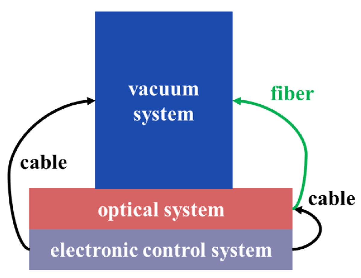
2.2. Experimental Apparatus

Our compact MOT apparatus comprises an optical system, a vacuum system, and an electronic control system, as shown in Figure 3. The vacuum system ensures an ultra-high vacuum environment to reduce the collisions between atoms and gas molecules. The optical system is responsible for the generation and regulation of lasers to achieve the cooling and trapping of atoms. Meanwhile, the electronic control system takes charge of the overall power management and control functions.

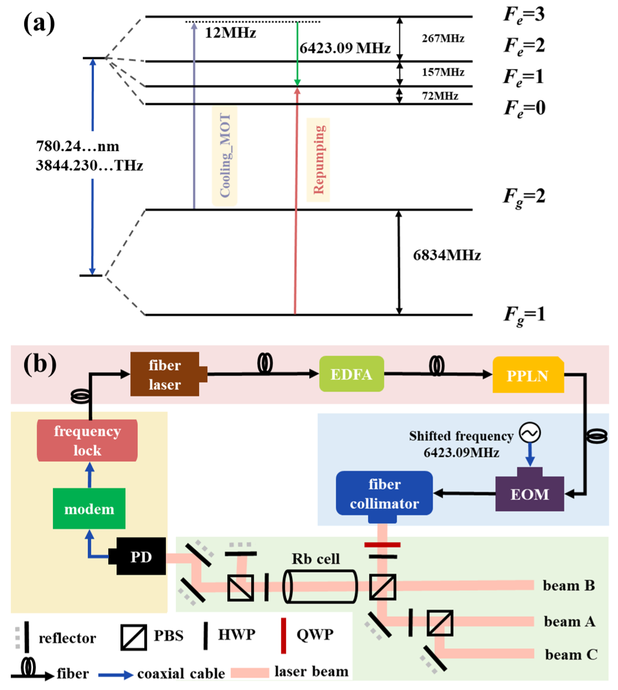
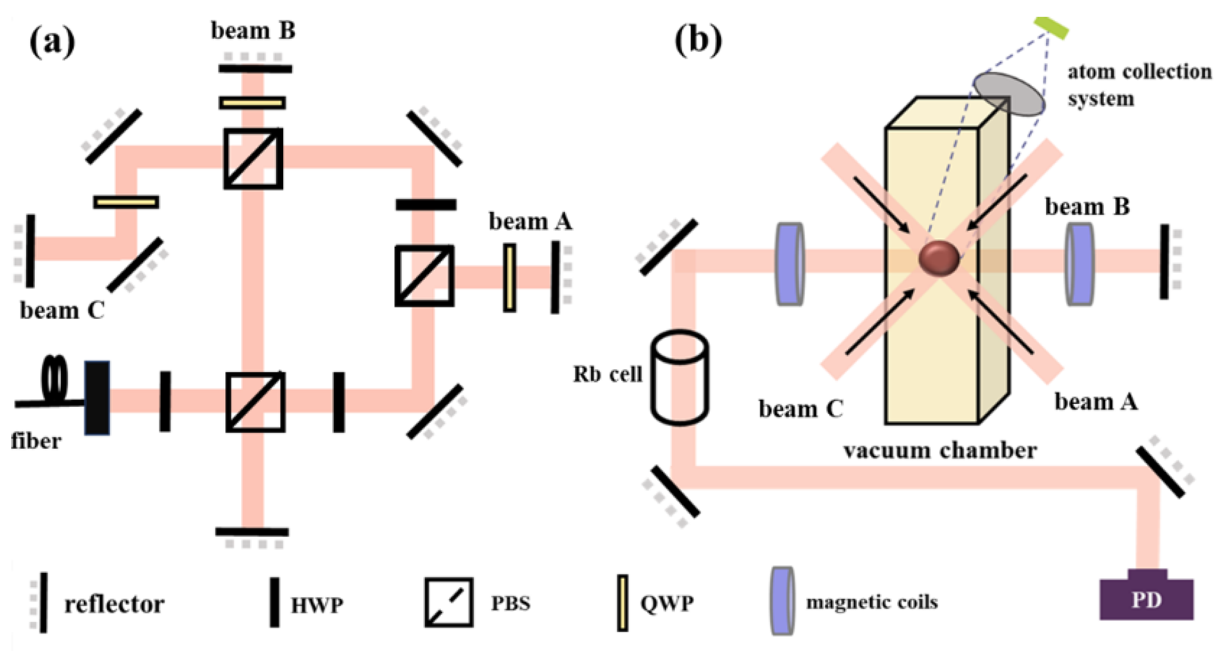
2.2.1. Optical System

Figure 4a illustrates the modulation frequency of different beams at various stages. As shown by the blue line, the laser frequency of the cooling beam used for atomic deceleration corresponds to a 5 2 S 1 / 2 , F = 2 5 2 S 3 / 2 , F = 3 transition red-detuned by 12 MHz. To compensate for the Doppler shift due to atomic motion, the laser frequency must be red-detuned from the atomic resonance frequency. Based on theoretical and experimental knowledge, this red detuning frequency is typically about 12 MHz [50]. Additionally, to avoid optical repumping during the cooling process, repumping beams (corresponding to 5 2 S 1 / 2 , F = 1 5 2 S 3 / 2 , F = 1 transition) is used to repump the atoms to the F = 1 state, as shown by the red line. In the experimental setup, we aim to use a single laser to produce a beam containing both cooling and repumping beams. This necessitates modulation with an EOM and adjustment of the fiber laser’s frequency. The calculation for the frequency shift is detailed below:
f ( F = 2 F = 3 ) 12 MHz = 384 , 228 , 103.20 MHz ,
f ( F = 1 F = 1 ) = 384 , 234 , 526.29 MHz .
The frequency of the cooling laser is 384,228,103.20 MHz, while the repumping laser frequency is 384,234,526.29 MHz. Consequently, the cooling beams need to be shifted by approximately 6423.09 MHz.
In the experiment, we adopted the optical path scheme shown in Figure 4b. A fiber laser in the laser source module is utilized to generate the laser beam, which has an initial emission wavelength of 1560.48 nm and the output power is 16.1 mW. Subsequently, the laser beam was amplified using an erbium-doped fiber amplifier (EDFA) with an amplified power of about 1 W. Given that the experiment requires a central wavelength of 780 nm, a Periodically Poled Lithium Niobate (PPLN) module is utilized to double the wavelength. Thereafter, the electro-optic modulator (EOM) in the frequency shift module is employed to fine-tune the frequency, resulting in a frequency shift of approximately 6423.09 MHz, as previously calculated.
In combination with Figure 4b for the description of the frequency-locked part, in the saturated absorption optical path module, the 780 nm laser beam is divided into two beams by a half-wave plate (HWP) and a polarizing beam splitter (PBS). The transmitted beam enters the main optical path, while the reflected beam is used for saturation absorption spectroscopy. Then, the saturated absorption spectrum of the Doppler background can be obtained though differentially amplifying the signals detected by the two photodetectors. This method is commonly used in laser frequency standards and laser cooling as it can directly eliminate Doppler broadening within an atomic vapor cell to obtain high-resolution laser spectra. In the frequency locking and driving module, the signal received by the photodetector is further processed by a demodulation board, which converts the digital signal into an analogue one. Subsequently, the analogue signal is connected via a radio-frequency coaxial cable to a frequency locking device for high-speed frequency-locking operations. This frequency-locking device is specifically designed to lock the frequency of the repumping beam. Eventually, the locked signal is transmitted back to the laser source through an optical fiber.
Regarding the application of the EOM, it is utilized to modulate the frequency of the laser, enabling the adjustment of the detuning in the cooling process. In the experiment, the signal generator generates a frequency of approximately 6423.09 MHz, which acts on the acousto-optic modulator. Through the EOM, a portion of the fixed-frequency cooling beam is shifted to become a fixed-frequency repumping beam. As a result, our laser beam path ultimately realizes a single-laser output, with the collected beam containing both the cooling and repumping beams at their respective frequencies. Capture of cold atoms requires the laser to be circularly polarized, so a larger-sized quarter-wave plate (QWP) is placed to convert the linearly polarized light to circularly polarized light before the laser beam enters the vacuum chamber. The power of the laser beam entering the vacuum cavity is about 45 mW, and the power of the cooling beam and repumping beam is approximately 43 mW and 2 mW. Considering the beam diameter is approximately 10 mm, the power density for the cooling beam is approximately 53.4 mW/cm2, and the power density for the repumping beam is approximately 3.8 mW/cm2. This power density is of critical importance as it directly impacts the cooling and loading efficiencies of the atoms in the MOT. Specifically, a higher power density can enhance the scattering forces exerted on the atoms, thus leading to more effective cooling and an increased loading rate into the trap.
We monitored the saturated absorption peak spectral signal and the modulation transfer spectrum signal of the system at a modulation frequency of approximately 6420 MHz, as illustrated in Figure 5. By comparing with the saturated absorption spectrum, the output frequency of the small absorption peak obtained on the far left in Figure 5 corresponds to the transition frequency of 87Rb from the F = 2 state to the F = 3 state. This allows us to identify that the measured downward peak on the right is an absorption enhancement due to the modulation of the first-order sideband under the influence of the F = 1 state, which corresponds to the saturated absorption peak of the repumping beams (corresponding to F = 1 F = 1 transition, indicated by the orange point). This system uses it as the target frequency position for laser locking.

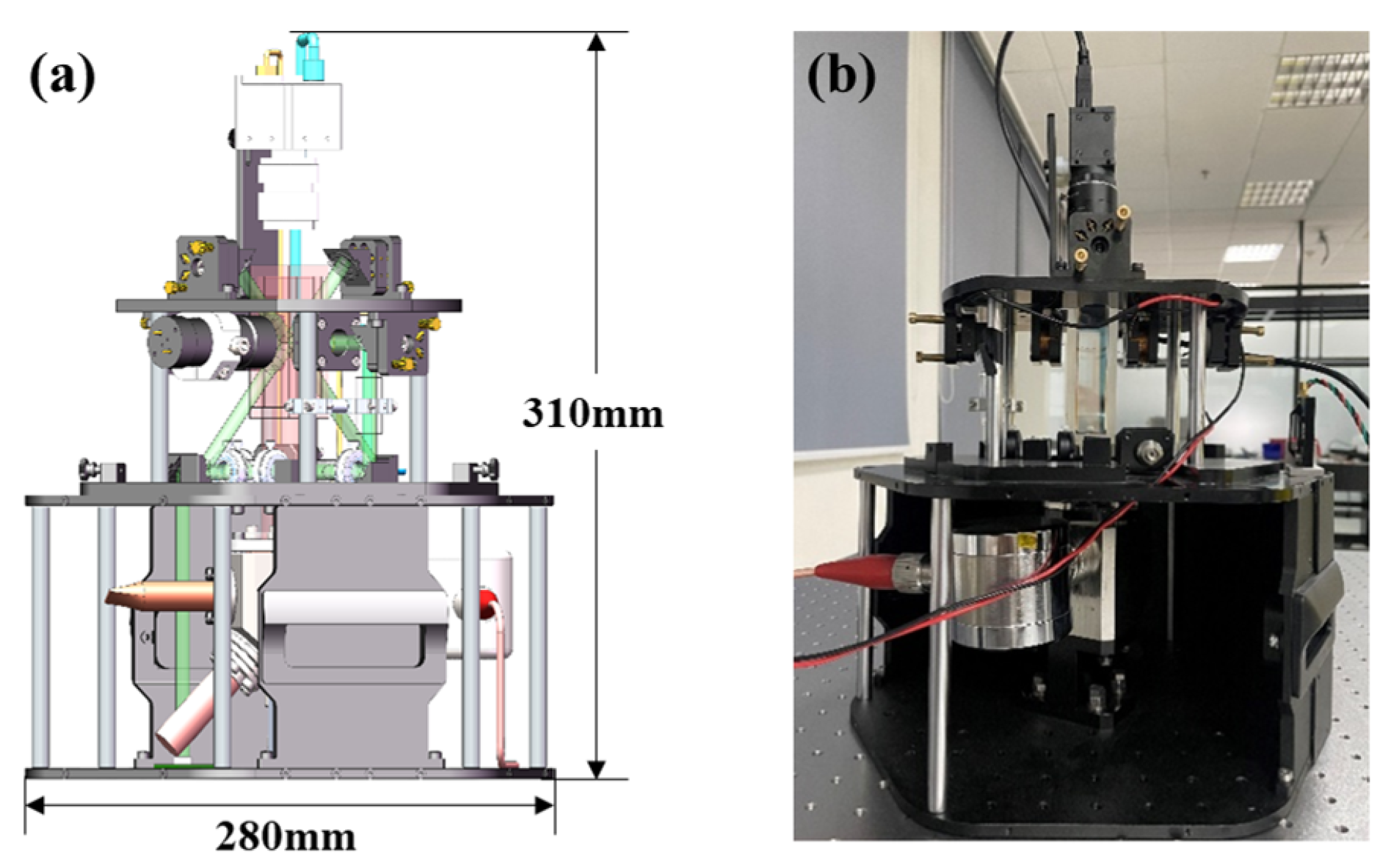
2.2.2. Vacuum System

The schematic and the photo of the vacuum system are shown in Figure 6a,b. The entire system comprises a support structure, a vacuum chamber, a spectroscopy module and a coil module. The external frame of the support structure consists of two hexahedrons, one on top of the other. It has a maximum diameter width of 0.28 m and a vertical height of 0.31 m. The total mass of the entire apparatus is 11.32 kg.
Cooling and trapping 87Rb atoms require an ultra-high vacuum environment, with a vacuum pressure of 10 6 or 10 7 Pa. In the experiment, the vacuum chamber we designed is shown in Figure 7, and the volume of the atomic cooling module is approximately 4.61 × 10 5 m3. According to the formula of flow conduction, the effective pumping velocity of the system is about 6.32 L/s to maintain the vacuum environment. First, we use a molecular pump connected to a vacuum acquisition module, achieving a vacuum pressure of 10 4 Pa. Then, we activated the vacuum maintenance module (an ion pump), continuing to evacuate and bake the chamber for about one week, obtaining a vacuum pressure of 10 7 Pa. Afterwards, we sealed the vacuum acquisition module and released rubidium atom, while keeping the ion pump running to maintain the ultra-high vacuum environment. The polygonal connecting part in the center shown in Figure 7 is made of titanium, and the individual parts are connected by titanium flanges, with indium wires acting as a sealing material between the glass window piece and the titanium, allowing for ultra-high vacuum in vacuum chambers.
Figure 8a shows the module of beam-splitting in the vaccum system of our compact MOT. In the design, a fixed structure is used to maintain a fixed distance between the reflector mirror, HWP, QWP, and PBS components. The structural design of each component is as compact as possible, avoiding any adjustable mechanical structures. Precise adjustments of the optical component are achieved using rotating elements with locking mechanisms. The precise alignment of the beam direction is accomplished using grinding shims and fine-tuning mirrors. Spacers control the distance between lenses, and threaded pressure rings secure the components within the lens barrel. According to the literature [51], this design helps improve optical path stability and durability. Through the beam splitting structure, the incident beam is uniformly divided into three beams A, B, and C. The optical power of each beam is about 15 mW, of which the cooling beam is about 14.3 mW and the repumping beam is 0.7 mW.
Figure 8b shows the vertical beam-splitting optical paths. As previously mentioned, the frequency of the repumping beam is locked with saturated absorption spectroscopy. In the cooling optical path, we installed a 87Rb vapor cell. Using a flexible optical path structure, part of the beam passing through the 87Rb vapor cell was split and reflected onto the photodetector for subsequent frequency locking. The atom number collection tube in Figure 8b is used to detect the fluorescence signal of the atom cloud and convert them into the atom population.
A single magnetic field coil was formed by winding a 0.6 mm diameter copper wire around a coil backbone with 20 turns per layer, comprising 6 layers in total. The two magnetic field coils were placed opposite to each other at a spatial location at a distance of 42 mm by applying a current of 1.2 A in the opposite direction and of equal magnitude. The magnetic field strength at the modified point was measured using a Gauss meter at a fixed position along the center axis of the coil set as shown in Figure 9a. The results of the measurement are shown in Figure 9b, and the magnetic field gradient of the MOT is estimated to be 11.61 Gs/cm.

2.2.3. Electronic Control System

The electronic control system is a crucial component of the cold atom MOT apparatus. It is responsible for power management and control functions, encompassing the power supply module, laser driving circuit, magnetic field control unit, and CCD module. The laser driving circuit precisely controls the power and frequency of the laser, ensuring that the laser beam can effectively cool and trap Rb atoms. Meanwhile, the magnetic field control unit adjusts the intensity and direction of the magnetic field in real-time to optimize the efficiency of atom capture. In addition, the CCD module records the experimental data. This integrated electronic control system not only enhances the stability and repeatability of the experiment but also provides significant data support for subsequent experiments.

3. Discussion

When designing the experimental apparatus, small windows were reserved on the top and sides of the device for installing the CCD camera to observe the trapping of the atom cloud. Figure 10a shows the atom cloud trapped after the magneto-optical trap was activated. When the voltage and current of the magnetic field coils in the MOT are maintained at 10 V and 1 A, respectively, the size of the atom cloud was determined to be approximately 1.3 mm by comparing the CCD images with the actual dimensions corresponding to the pixels.
We used a photodetector in the atom number collection tube to measure the real-time number of atoms trapped by the switching laser over a period. The photodetector converts the optical signal emitted by the atoms into an electrical signal, resulting in the atom loading voltage curve shown in Figure 10b. According to
N = P d A 1 × A 2 = V η × A η 1 × η 2 × D 2 × × ω 64 × L 2 × c 1 × Γ ω R 2 δ 2 + Γ 2 / 4 + c 2 × ω R 2 / 2 ,
N represents the number of trapped atoms, η represents P d conversion efficiency of 0.45 A/W, A represents the amplifier gain is 1 × 10 7 , η 1 and η 2 are the transmittances of the optical windows, approximately 0.95. D is the lens diameter of 0.02 m, is Planck’s constant with a value of approximately 6.626 × 10 34 J·s, L is the distance from the lens to the atoms (0.06 m), Γ = 2 π Γ v is the natural linewidth ( Γ v = 6.07 MHz), c 1 and c 1 are parameters related to the arrangement of the relevant Zeeman sublevel energies (under the weak beams approximation, the atomic population in the associated Zeeman sublevels is uniformly distributed; for rubidium atoms, this value is 0.46), and ω is the angular frequency,
ω = 2 π c λ wl ,
where c is the speed of beam, and λ is the wavelength of the 87Rb D2 line in vacuum. In Equation (3), ω r refers to the Rabi frequency,
ω r = s · Γ 2 2 ,
where s is the saturation parameter, which represents the ratio of the input laser intensity to the saturation intensity.
From Figure 10b, it can be seen that over a period of 400 ms, the voltage difference measured by the photodetector is 0.77 V. Calculations show that the number of trapped atoms is approximately 7.17 × 10 6 , which corresponds to an atom loading rate of about 1.79 × 10 7 atoms per second. When comparing these values with other reports in the literature for Rb MOTs, it is evident that our loading rate and total atom number are on the lower end of the spectrum. For instance, typical Rb MOTs often report loading rates in the range of 108 to 109 atoms per second, and the system designed by Zhejiang University achieves a loading rate of 2.8 × 10 9 atoms/s for the MOT [52]. Several factors may contribute to our observed lower values. Firstly, the efficiency of the cooling and trapping process can be affected by the laser power, small spot size and beam overlap. In our setup, the laser power may not be optimized for maximum loading efficiency, leading to fewer atoms being trapped. In addition, the alignment accuracy of the optical components in the MOT has a significant impact on the loading rate. Misalignment or suboptimal beam configuration can reduce the effective interaction volume, further limiting the number of atoms that can be captured. Moreover, in our setup, any limitations in the coil configuration, current settings, or spacing can impact the effectiveness of the magnetic field gradient, ultimately affecting the overall performance of the MOT. Future optimization in these perspectives may enhance our loading rates and total atom numbers significantly.
In the future, we will add a detection beam to the spatial optical path in the vacuum system, as shown in Figure 11a. The detection beam will be positioned below the center of the MOT that is fully resonant with the 5 2 S 1 / 2 F = 2 5 2 S 3 / 2 F = 3 . After establishing this configuration, we will simultaneously turn off the laser and magnetic fields for a designated period, allowing the atoms to fall and expand freely under the influence of gravity. Due to the varying velocities of the atoms, the time taken for them to traverse the detection region will differ, enabling us to obtain a fluorescence intensity curve as a function of TOF. This curve will represent the velocity distribution of the atomic ensemble and can be fitted to determine the initial temperature of the atom cloud. Meanwhile, another method is to use CCD to capture the fluorescence emitted by the cold atom. The detection beam will facilitate fluorescence imaging of the atom cloud, and the resulting images will be processed and analyzed to extract temperature information about the cold atomic ensemble.
We also plan to utilize the current setup for related cold atom interference experiments by introducing a biased magnetic field, utilizing blowing light, and installing a microwave antenna to generate π -pulses. This will allow us to prepare atoms in the m F = 0 state. Specifically, a linearly polarized microwave π -pulse with a frequency of 6.834 GHz was used to excite the atom from F = 2 , m F = 0 to F = 1 , m F = 0 , and then the atoms at the rest of the sub-energy level of 5 2 S 1 / 2 F = 2 are blown off by the blow beam, which is in resonance with the 5 2 S 1 / 2 , F = 2 5 2 P 3 / 2 , F = 3 transition. After this preparation, a Raman beam will interact with the atoms, enabling us to obtain the interference signals of the internal states of cold atoms, as depicted in Figure 11b. Initially, two Raman laser pulses with a duration time of τ will act on the cold atomic ensemble, giving the atoms a 50 % probability of undergoing a two-photon stimulated Raman transition to the excited state. Concurrently, due to the momentum recoil from the photons, the atoms in the excited state will be spatially separated from those in the ground state along the z-direction, effectively realizing the splitting of the cold atom ensemble. After a time of T, a second set of Raman laser pulses, again with a duration time of 2 τ , will be applied, allowing the atoms in the excited state to return to the ground state while simultaneously facilitating transitions for the atoms in the ground state to the excited state. This process will alter the atomic trajectories, achieving the reflection of the cold atom ensemble. Finally, a Raman laser pulse with a duration time of τ will be used to complete the merging of the atomic beams. The number of atoms in the e state (or g state) will be detected, yielding atomic interference fringes. By analyzing the phase and intensity variations in the interference fringes, we can precisely lock the microwave frequency, thereby achieving high-precision time measurement with the cold atomic clock. At the same time, in the cold atom interference path, gravitational effects and other external field factors will induce changes in the interference phase, allowing us to utilize the signal to measure gravitational acceleration and rotation.

4. Conclusions

This paper has demonstrated the successful development of our compact MOT system, in which the height of the unit is 0.7 m, the volume is 6.3 × 10 2 m 3 and the mass is 11.32 kg. The primary purpose of this setup is to create a portable and efficient system for atomic cooling, suitable for applications in cold atom physics, quantum computing, and precision measurement. To meet the requirements for effective atomic cooling, we designed the optical path to utilize a single laser source to generate two different frequencies necessary for the cooling beam and repumping beam. This was achieved by internally splitting the beam, performing frequency shifts, and then recombining the two beams. This innovative approach allows for precise control of both the cooling and repumping processes.
The atom loading experiments show that the system achieves an atom loading rate of 1.79 × 10 7 87Rb atoms per second, indicating excellent loading efficiency and stability in capturing and cooling 87Rb atoms. When compared to existing systems, these parameters align well with the requirements for effective operation in various applications, demonstrating that our setup meets the necessary criteria for size, weight, and performance. This research provides valuable insights and new approaches for the development of compact MOT systems, holding promise for advancing the field of cold atom physics. Future optimizations and improvements are expected to broaden the system’s application range, enhancing its utility in scientific research and technological innovation.

Author Contributions

Conceptualization, S.B. and B.W.; methodology, S.B. and Y.Z.; software, P.C. and X.G.; project administration, D.L., J.N. and C.Z.; resources, B.C.; data curation, K.W.; writing—original draft preparation, S.B.; writing—review and editing, B.W. and X.W.; supervision, Q.L. All authors have read and agreed to the published version of the manuscript.

Funding

This research was funded by Research and Application Experiment of Carrying Measurement and Support Technology for Ocean Route (Project No.: DD20230644) and National Key Research and Development Program under Grant (Project No.: 2023YFC2907000).

Institutional Review Board Statement

Not applicable.

Informed Consent Statement

Not applicable.

Data Availability Statement

The data presented in this study are available on request from the corresponding author.

Acknowledgments

The authors are grateful to other colleagues for their help during the period of experimental measurement.

Conflicts of Interest

The authors declare no conflicts of interest.

References

  1. Phillips, W.D. Nobel Lecture: Laser cooling and trapping of neutral atoms. Rev. Mod. Phys. 1998, 70, 721. [Google Scholar] [CrossRef]
  2. Slusher, R.; Hollberg, L.; Yurke, B.; Mertz, J.; Valley, J. Observation of squeezed states generated by four-wave mixing in an optical cavity. Phys. Rev. Lett. 1985, 55, 2409. [Google Scholar] [CrossRef] [PubMed]
  3. Phillips, W.D.; Metcalf, H. Laser deceleration of an atomic beam. Phys. Rev. Lett. 1982, 48, 596. [Google Scholar] [CrossRef]
  4. Aspect, A.; Arimondo, E.; Kaiser, R.E.A.; Vansteenkiste, N.; Cohen-Tannoudji, C. Laser cooling below the one-photon recoil energy by velocity-selective coherent population trapping. Phys. Rev. Lett. 1988, 61, 826. [Google Scholar] [CrossRef]
  5. Gerginov, V.; Nemitz, N.; Weyers, S.; Schröder, R.; Griebsch, D.; Wynands, R. Uncertainty evaluation of the caesium fountain clock PTB-CSF2. Metrologia 2009, 47, 65. [Google Scholar] [CrossRef]
  6. Elgin, J.D.; Heavner, T.P.; Kitching, J.; Donley, E.A.; Denney, J.; Salim, E.A. A cold-atom beam clock based on coherent population trapping. Appl. Phys. Lett. 2019, 115, 033503. [Google Scholar] [CrossRef]
  7. Levi, F.; Calonico, D.; Calosso, C.E.; Godone, A.; Micalizio, S.; Costanzo, G.A. Accuracy evaluation of ITCsF2: A nitrogen cooled caesium fountain. Metrologia 2014, 51, 270. [Google Scholar] [CrossRef]
  8. Heavner, T.P.; Donley, E.A.; Levi, F.; Costanzo, G.; Parker, T.E.; Shirley, J.H.; Ashby, N.; Barlow, S.; Jefferts, S. First accuracy evaluation of NIST-F2. Metrologia 2014, 51, 174. [Google Scholar] [CrossRef]
  9. Fang, F.; Chen, W.; Liu, K.; Liu, N.; Suo, R.; Li, T. Design of the new NIM6 fountain with collecting atoms from a 3D MOT loading optical molasses. In Proceedings of the 2015 Joint Conference of the IEEE International Frequency Control Symposium & the European Frequency and Time Forum, Denver, CO, USA, 12–16 April 2015; IEEE: New York, NY, USA, 2015; pp. 492–494. [Google Scholar]
  10. Fang, F.; Li, M.; Lin, P.; Chen, W.; Liu, N.; Lin, Y.; Wang, P.; Liu, K.; Suo, R.; Li, T. NIM5 Cs fountain clock and its evaluation. Metrologia 2015, 52, 454. [Google Scholar] [CrossRef]
  11. Kasevich, M.; Chu, S. Measurement of the gravitational acceleration of an atom with a light-pulse atom interferometer. Appl. Phys. B 1992, 54, 321–332. [Google Scholar] [CrossRef]
  12. Poli, N.; Wang, F.Y.; Tarallo, M.; Alberti, A.; Prevedelli, M.; Tino, G. Precision Measurement of Gravity with Cold Atoms in an Optical Lattice and Comparison with a Classical Gravimeter. Phys. Rev. Lett. 2011, 106, 038501. [Google Scholar] [CrossRef] [PubMed]
  13. Merlet, S.; Bodart, Q.; Malossi, N.; Landragin, A.; Dos Santos, F.P.; Gitlein, O.; Timmen, L. Comparison between two mobile absolute gravimeters: Optical versus atomic interferometers. Metrologia 2010, 47, L9. [Google Scholar] [CrossRef]
  14. Schmidt, M.; Senger, A.; Hauth, M.; Freier, C.; Schkolnik, V.; Peters, A. A mobile high-precision absolute gravimeter based on atom interferometry. Gyroscopy Navig. 2011, 2, 170–177. [Google Scholar] [CrossRef]
  15. Vitushkin, L.F. Absolute gravity measurements. In Encyclopedia of Geodesy; Springer: Cham, Switzerland, 2014. [Google Scholar] [CrossRef]
  16. Altin, P.; Johnsson, M.; Negnevitsky, V.; Dennis, G.; Anderson, R.P.; Debs, J.; Szigeti, S.; Hardman, K.; Bennetts, S.; McDonald, G.; et al. Precision atomic gravimeter based on Bragg diffraction. N. J. Phys. 2013, 15, 023009. [Google Scholar] [CrossRef]
  17. DiFrancesco, D.; Grierson, A.; Kaputa, D.; Meyer, T. Gravity gradiometer systems–Advances and challenges. Geophys. Prospect. 2009, 57, 615–623. [Google Scholar] [CrossRef]
  18. Moody, M.V.; Paik, H.J.; Canavan, E.R. Three-axis superconducting gravity gradiometer for sensitive gravity experiments. Rev. Sci. Instrum. 2002, 73, 3957–3974. [Google Scholar] [CrossRef]
  19. Gustavson, T.; Bouyer, P.; Kasevich, M. Precision rotation measurements with an atom interferometer gyroscope. Phys. Rev. Lett. 1997, 78, 2046. [Google Scholar] [CrossRef]
  20. Gustavson, T.; Landragin, A.; Kasevich, M. Rotation sensing with a dual atom-interferometer Sagnac gyroscope. Class. Quantum Gravity 2000, 17, 2385. [Google Scholar] [CrossRef]
  21. Fang, J.; Qin, J. Advances in atomic gyroscopes: A view from inertial navigation applications. Sensors 2012, 12, 6331–6346. [Google Scholar] [CrossRef]
  22. Monroe, C.; Robinson, H.; Wieman, C. Observation of the cesium clock transition using laser-cooled atoms in a vapor cell. Opt. Lett. 1991, 16, 50–52. [Google Scholar] [CrossRef]
  23. Haus, H.A.; Huang, W. Coupled-mode theory. Proc. IEEE 1991, 79, 1505–1518. [Google Scholar] [CrossRef]
  24. Gallagher, A.; Pritchard, D.E. Exoergic collisions of cold Na-Na. Phys. Rev. Lett. 1989, 63, 957. [Google Scholar] [CrossRef] [PubMed]
  25. Sesko, D.; Walker, T.; Monroe, C.; Gallagher, A.; Wieman, C. Collisional losses from a light-force atom trap. Phys. Rev. Lett. 1989, 63, 961. [Google Scholar] [CrossRef] [PubMed]
  26. Jessen, P.S.; Gerz, C.; Lett, P.D.; Phillips, W.D.; Rolston, S.; Spreeuw, R.; Westbrook, C. Observation of quantized motion of Rb atoms in an optical field. Phys. Rev. Lett. 1992, 69, 49. [Google Scholar] [CrossRef]
  27. Julienne, P.S.; Vigué, J. Cold collisions of ground-and excited-state alkali-metal atoms. Phys. Rev. A 1991, 44, 4464. [Google Scholar] [CrossRef]
  28. Zhang, S. Acta Physica Sinica. Acta Phys. Sin. 2005. [Google Scholar]
  29. Doherty, A.; Parkins, A.; Tan, S.; Walls, D. Motion of a two-level atom in an optical cavity. Phys. Rev. A 1997, 56, 833. [Google Scholar] [CrossRef]
  30. Lett, P.D.; Watts, R.N.; Westbrook, C.I.; Phillips, W.D.; Gould, P.L.; Metcalf, H.J. Observation of atoms laser cooled below the Doppler limit. Phys. Rev. Lett. 1988, 61, 169. [Google Scholar] [CrossRef]
  31. Yuntao, C.; Xiangxiang, L.; Delong, K.; Luyan, N. Design of Ultra-High Vacuum System for Magneto-Optical Trap of Rb Atom. Navig. Position. Timing 2018, 5, 82–86. [Google Scholar] [CrossRef]
  32. Vovrosh, J.; Wilkinson, K.; Hedges, S.; McGovern, K.; Hayati, F.; Carson, C.; Selyem, A.; Winch, J.; Stray, B.; Earl, L.; et al. Magneto-optical trapping in a near-suface borehole. PLoS ONE 2023, 18, e0288353. [Google Scholar] [CrossRef]
  33. Hui, D.; Bei, G.; Dianqiang, S.; Zhonghua, J.; Yuan, J.; Yifei, M.; Yanting, Z. Portable Miniaturized Magneto-Optical Trap System. Laser Technol. 2023, 1–10. Available online: https://www.scholarmate.com/S/12n35t (accessed on 18 January 2025).
  34. Shimizu, F.; Shimizu, K.; Takuma, H. Four-beam laser trap of neutral atoms. Opt. Lett. 1991, 16, 339–341. [Google Scholar] [CrossRef] [PubMed]
  35. Lee, K.; Kim, J.; Noh, H.; Jhe, W. Single-beam atom trap in a pyramidal and conical hollow mirror. Opt. Lett. 1996, 21, 1177–1179. [Google Scholar] [CrossRef] [PubMed]
  36. Pollock, S.; Cotter, J.; Laliotis, A.; Hinds, E. Integrated magneto-optical traps on a chip using silicon pyramid structures. Opt. Express 2009, 17, 14109–14114. [Google Scholar] [CrossRef] [PubMed]
  37. Lee, J.; Grover, J.; Orozco, L.; Rolston, S. Sub-Doppler cooling of neutral atoms in a grating magneto-optical trap. JOSA B 2013, 30, 2869–2874. [Google Scholar] [CrossRef]
  38. Hyodo, M.; Nakayama, K.; Watanabe, M.; Ohmukai, R. Mirror magneto-optical trap exploiting hexapole-compensated magnetic field. Phys. Rev. A—At. Mol. Opt. Phys. 2007, 76, 013419. [Google Scholar] [CrossRef]
  39. Isichenko, A.; Chauhan, N.; Bose, D.; Wang, J.; Kunz, P.D.; Blumenthal, D.J. Photonic integrated beam delivery for a rubidium 3D magneto-optical trap. Nat. Commun. 2023, 14, 3080. [Google Scholar] [CrossRef]
  40. Debye, P. Einige bemerkungen zur magnetisierung bei tiefer temperatur. Ann. Phys. 1926, 386, 1154–1160. [Google Scholar] [CrossRef]
  41. Giauque, W. A thermodynamic treatment of certain magnetic effects. A proposed method of producing temperatures considerably below 1 absolute. J. Am. Chem. Soc. 1927, 49, 1864–1870. [Google Scholar] [CrossRef]
  42. Chu, S. Nobel Lecture: The manipulation of neutral particles. Rev. Mod. Phys. 1998, 70, 685. [Google Scholar] [CrossRef]
  43. Cohen-Tannoudji, C.N. Nobel Lecture: Manipulating atoms with photons. Rev. Mod. Phys. 1998, 70, 707. [Google Scholar] [CrossRef]
  44. Metcalf, H.J.; Van der Straten, P. Laser Cooling and Trapping; Springer Science & Business Media: New York, NY, USA, 1999; Available online: https://api.semanticscholar.org/CorpusID:14942756 (accessed on 18 January 2025).
  45. McCarron, D. Laser cooling and trapping molecules. J. Phys. B At. Mol. Opt. Phys. 2018, 51, 212001. [Google Scholar] [CrossRef]
  46. Kox, A.J. The discovery of the electron: II. The Zeeman effect. Eur. J. Phys. 1997, 18, 139. [Google Scholar] [CrossRef]
  47. Harmin, D.A. Theory of the Stark effect. Phys. Rev. A 1982, 26, 2656. [Google Scholar] [CrossRef]
  48. Pipkin, F.M. 1966 Nobel Laureate in Physics: Alfred Kastler. Science 1966, 154, 747–749. [Google Scholar] [CrossRef]
  49. Raab, E.L.; Prentiss, M.; Cable, A.; Chu, S.; Pritchard, D.E. Trapping of neutral sodium atoms with radiation pressure. Phys. Rev. Lett. 1987, 59, 2631. [Google Scholar] [CrossRef]
  50. Wang, J.; Zhu, Y.; Jiang, K.; Zhan, M. Bichromatic electromagnetically induced transparency in cold rubidium atoms. Phys. Rev. A 2003, 68, 063810. [Google Scholar] [CrossRef]
  51. Wenwen, L.; Qian, L.; Angang, L.; Yu, X.; Lin, L.; Rui, L.; Jie, M.; Taijun, P.; Bin, W.; Xinping, X.; et al. Integrated Design and Realization of Two-Dimensional Magneto-Optical Trap for Ultra-Cold Atomic Physics Rack in Space. China Laser 2022, 49, 193–202. [Google Scholar]
  52. Daji, Z.; Min, H.; Xian, Z.; Kaikai, H.; Xuanhui, L. 2D cold atomic beam system for increasing the loading rate of 3D MOT. Infrared Laser Eng. 2019, 48, 0506003. [Google Scholar] [CrossRef]
Figure 1. Physical diagram of Doppler cooling mechanism.
Photonics 12 00098 g001
Figure 2. Schematic diagram of the magneto-optical trap principle. (a) Typical structure schematic of 3D-MOT. (b) Schematic diagram of a two energy level system.
Photonics 12 00098 g002
Figure 3. The schematic diagram of MOT apparatus.
Photonics 12 00098 g003
Figure 4. Diagram of the compact optical path. (a) Energy level diagram for the D2 transition of 87Rb and laser frequency required for cold atom preparation. The green line represents the frequency of the electro-optic modulator (EOM), which needs to be tuned to 6423.09 MHz. (b) The optical path, where the pink area represents the laser source module. The blue area represents the frequency shift module, the green area represents the saturated absorption optical path module, and the yellow area represents the frequency locking and driving module.
Photonics 12 00098 g004
Figure 5. Saturated absorption spectral signal and the corresponding modulation transfer spectrum signal at a modulation frequency of 6420 MHz. The gray line represents the saturated absorption spectral signal, while the red line denotes the modulation transfer spectrum signal.
Photonics 12 00098 g005
Figure 6. Compact vacuum system. (a) Schematic of the vacuum system; (b) photo of homemade vacuum system.
Photonics 12 00098 g006
Figure 7. Schematic of vacuum chamber.
Photonics 12 00098 g007
Figure 8. Schematic of spectroscopy module. (a) Planar basal beam-splitting optical path: when observing the planar optical path of the lower basal plate within the vacuum chamber from above, an assembly comprising a reflector, HWP, QWP, and PBS is utilized to split the incident beam into beams A, B, and C. (b) Vertical beam-splitting optical path: A schematic representation of the vertical optical path of the vacuum chamber when viewed from the left to the right (with certain optical elements omitted). Multiple optical components are employed to generate counter-propagating beams for beams A, B, and C, which converge at the center of the vacuum chamber. Additionally, a pair of anti-Helmholtz coils are positioned opposite to each other on the left and right sides of the chamber center for cold atom trapping.
Photonics 12 00098 g008
Figure 9. The design of magnetic field coil: (a) The diagram of magnetic field test setup, where yellow dots are the locations of our test points; (b) the measurement data of magnetic field gradient of MOT.
Photonics 12 00098 g009
Figure 10. Schematic of the trapped atom cloud. (a) The image of the atom cloud; (b) The atom loading voltage curve, the red dots in the figure show the maximum and minimum values of the collected voltages over a period of time, respectively, and we need their differences for calculations.
Photonics 12 00098 g010
Figure 11. (a) Schematic diagram of atomic temperature measurement based on the method of Time of Flight (TOF); (b) principle of cold atom interferometry.
Photonics 12 00098 g011
Disclaimer/Publisher’s Note: The statements, opinions and data contained in all publications are solely those of the individual author(s) and contributor(s) and not of MDPI and/or the editor(s). MDPI and/or the editor(s) disclaim responsibility for any injury to people or property resulting from any ideas, methods, instructions or products referred to in the content.

