Article

Multi-Channel Vibration Measurements Based on a Self-Mixing Vertical-Cavity Surface-Emitting Laser Array

1
School of Computer and Electronic Information, Nanjing Normal University, Nanjing 210023, China
2
Division of Dimensional Metrology, Jiangsu Institute of Metrology, Nanjing 210023, China
*
Author to whom correspondence should be addressed.
Photonics 2025, 12(3), 178; https://doi.org/10.3390/photonics12030178
Submission received: 17 December 2024 / Revised: 21 January 2025 / Accepted: 28 January 2025 / Published: 21 February 2025

Abstract

:
This paper studied a multi-channel self-mixing interferometric vibration measurement system based on a vertical-cavity surface-emitting laser array. A 1 × 8 laser array was utilized to irradiate multiple positions of a vibrating target to establish independent measurement channels. The reflected light beams, carrying the vibration information of each position, were redirected back into the laser and coherently mixed with the original optical field, generating the self-mixing interference. The interferometric signals were measured by monitoring the junction voltage variations across the terminals of the VCSEL array. A denoising filtering method based on the variational mode decomposition with Hausdorff distance was proposed to improve the signal-to-noise ratio. Furthermore, the vibration waveforms of different positions were reconstructed using the Hilbert transform-based orthogonal phase demodulation technology. Both simulations on synthetic signals and experiments with real datasets were conducted to validate the feasibility and stability of the proposed method. Due to the array detection configuration, the system boasted a simple and compact structure, low power consumption, and easy extensibility, laying the groundwork for high accuracy and multi-dimensional vibration detection in industrial applications.

1. Introduction

In recent decades, with the dramatically increasing demand for vibration measurements in many cutting-edge fields such as turbine blade vibration, ground testing, nanotechnology, and so on, it has become more crucial to realize the multi-dimensional precision measurement of complex vibration specimens using portable high-precision measuring instruments [1,2,3]. Among other measurement methods, laser self-mixing interferometry (SMI) has the advantages of an ultra-compact structure, self-collimation, large coherence length, and the capability to be applied to rough scattering surfaces. Due to the presence of feedback light, the instantaneous output power and phase of the laser are both altered, and the minor variation in operation conditions offers novel approaches for the accurate measurement of diverse physical quantities [4,5,6]. Extensive research based on gas lasers, diode lasers, micro-chip lasers, DFB lasers, and fiber lasers has been reported, making the SMI evolve into a powerful and robust instrument tool for vibration measurements [7,8,9,10,11,12,13,14]. S. Donati reviewed the development of configurations and experimental performance in SMI instruments for vibration measurements [15]. In most SMI configurations, the acquisition of the interferometric signals is performed by monitoring the photocurrent fluctuation caused by the variation in optical output power. In addition, the detection process can also be achieved by extracting the feedback-induced laser frequency change using several kinds of edge filters, including fiber Bragg gratings, vapor cells, and the Mech–Zehnder interferometer [16,17,18]. Either the direct or the frequency-to-intensity conversion-based detection method inevitably requires additional photodetectors, some of which are independent of the optical path, while others are encapsulated inside laser packages. The adoption of detectors not only increases the cost and structural complexity of the system but also limits the development of SMI towards optical integration. When it comes to measuring the motion of multiple targets or some complex vibration modes, laser array-based interferometers provide higher efficiency. The positional scanning of the single laser is replaced by parallel measurements of array lasers, greatly reducing the measurement time. However, due to the difficulty of configuring laser arrays and the requirement of a large number of detectors, it is not feasible for current SMIs to perform multi-channel vibration measurements.
Compared with other lasers, the characteristics of vertical-cavity surface-emitting lasers (VCSELs) make them very suitable for optical integration. The laser beam is emitted vertically from the top of the laser with a circular profile, and the low threshold current and power consumption further improve integration efficiency and convenience. The optical output power of VCSELs can be measured as a perturbation of the diode junction voltage while a constant injection current is supplied. Since no external detector is required, the structure of the whole system is extremely simple, and the measurable bandwidth can achieve gigahertz. The advent of low-cost commercial VCSELs promotes the development of SMI technology in the field of optical integration, paving the way for the realization of multi-channel measurement. VCSEL-based SMI has been studied, and the measurements of rotational speed and liquid flow rate were reported with high resolution [19,20,21]. Actually, the signal-to-noise ratio (SNR) for the junction voltage detection scheme is lower in contrast to the approaches utilizing independent photodiodes, so the appropriate denoising process is indispensable. Variational mode decomposition (VMD) is an adaptive signal processing method proposed by Dragomiretskiy and Zosso in 2014 [22]. It has many advantages in processing non-recursive signals, overcoming the modal mixing problem in empirical modal decomposition by using Wiener filtering properties to obtain better filtering results. This algorithm decomposes an input signal to obtain the relevant modes around the center frequencies in the frequency domain. It provides excellent accuracy and stability for the extraction of very weak feature signals in strong noise environments, so it can be used to refine the variation in junction voltage across the laser diode. In [23], the feasibility of the VMD filtering method in a laser self-mixing interferometer was verified, but the strict quantitative description of the effective modes in the VMD method is not sufficient. Furthermore, it is a significant challenge to extend this method for the synchronous denoising of multi-channel measurement signals.
In this work, a detector-free multi-channel vibrometer based on an array of 1 × 8 self-mixing VCSELs is presented. Eight laser beams impinge on separate positions of a vibrating diaphragm, and the reflected lights are returned back to individual lasers, generating the laser self-mixing interference. The interferometric signals were acquired by monitoring the junction voltage from independent VCSELs. A filtering algorithm based on the VMD and Hausdorff distance (HD) is proposed to improve the SNR, and the Hilbert transform method is utilized to determine the interferometric phase of each measurement channel. The experimental results show that the developed vibrometer is able to simultaneously reconstruct the motion of eight targets with high accuracy. With the development of optical integration technology, the VCSEL-based self-mixing vibrometer becomes more compact, robust, and powerful, playing an even more significant role in multi-channel vibration measurement applications.

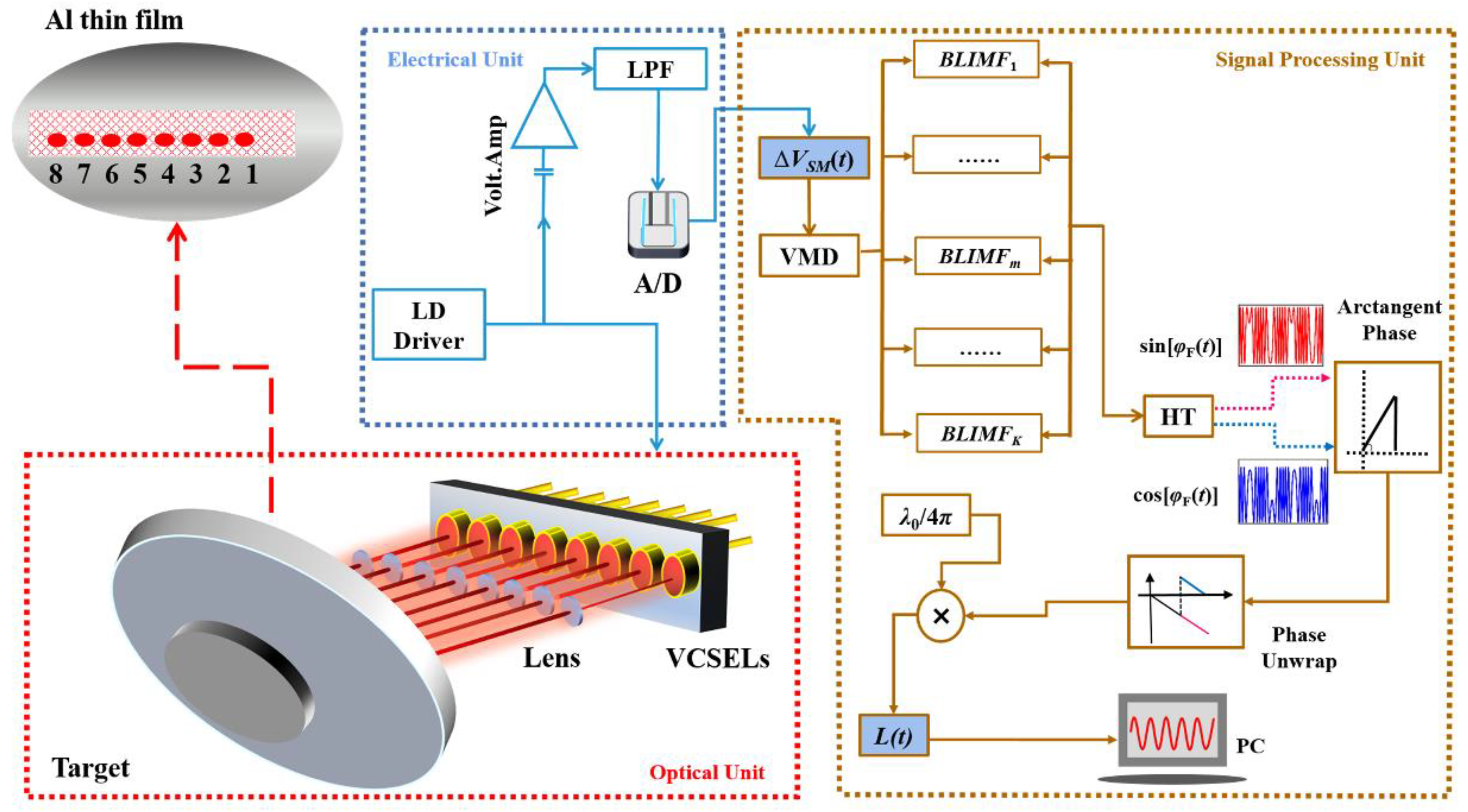
2. Measurement Principle

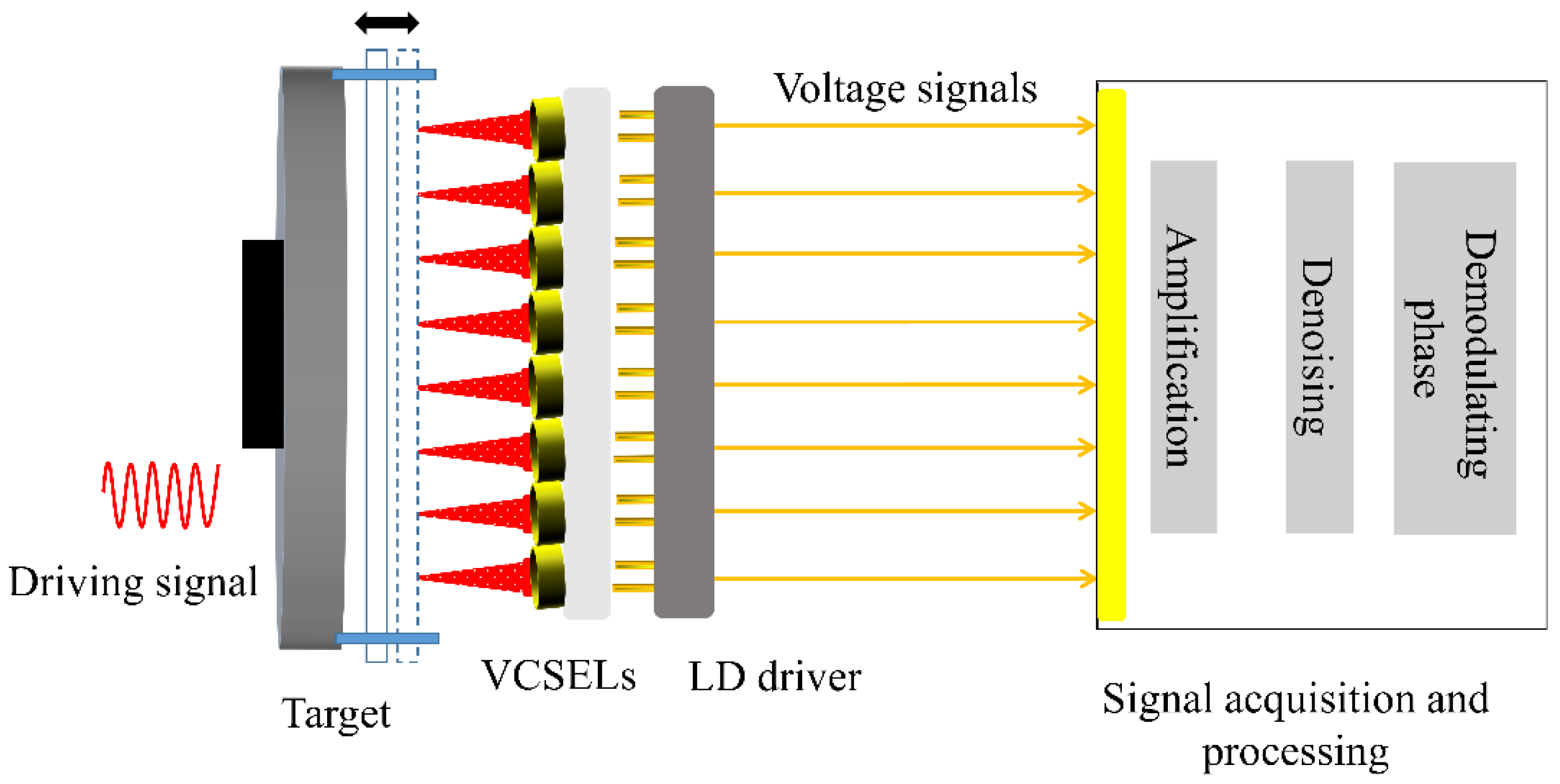
2.1. Self-Mixing Interference Based on the VCSEL Array

The schematic diagram of the proposed multi-channel SMI based on the VCSEL array is shown in Figure 1. An array of VCSELs is evenly placed on a substrate to form 1 × 8 parallel independent measurement channels. Eight single-mode linearly polarized laser beams are emitted, collimated, and then directed normally onto a vibrating aluminum plate which is fixed to a loudspeaker. The initial distance between the VCSEL array and the target is about 20 mm. And the beam path length between the laser and the vibrating target varies periodically when the speaker is driven by a sinusoidal voltage signal. The reflected light beams, carrying the vibration information, are allowed to re-inject the laser source and coherently mix with the original optical field within the resonant cavity, respectively. As a result, self-mixing interference occurs, and eight independent measurement channels are formed. Caused by the reduction in quasi-Fermi level separation due to carrier depletion, the self-mixing interference effect not only changes the photon density of the laser but also alters the carrier density on the PN junction voltage of the semiconductor laser. Therefore, the eight-channel self-mixing signals, in our case, were measured by monitoring the junction voltage variations across the terminals of the VCSEL array. The collected self-mixing signals were sent to a signal acquisition and processing unit, where the signals were amplified, filtered, and then demodulated to reconstruct the vibration of the objects.
The change in the carrier concentration of each VCSEL induced by the optical feedback could be modeled by the Lang and Kobayashi equations, and its dependence on the phase of the external cavity can be expressed as follows:
Δ N t = 2 κ e x t G N τ l cos φ ( t )
with
φ t = 4 π L t λ
where ΔN(t) is the variation in the concentration of PN junction carriers with optical feedback; κext denotes the coupling coefficient, the magnitude of which depends on the laser end-face reflectivity and the coherent coupling efficiency factor of the feedback optical field; GN = vg∂G/∂N is the mode gain coefficient under optical feedback with vg of the group velocity of carriers; τl is the round-trip delay in the lasing cavity; and φ(t) is the external cavity phase to be measured, which is determined by the external length L(t) and the central lasing wavelength λ.
Considering that the laser operates under the steady-state condition, the junction voltage V of the semiconductor laser with regards to the carrier density N can be written as follows:
V t = 2 k B T e ln N t N i
where kB is the Boltzmann constant; e represents the carrier charge; T is the temperature of the junction; and Ni is the intrinsic carrier density of the laser. Equation (3) shows a logarithmic relationship between the carrier density and the voltage V across the PN junction. Assuming that the VCSEL is operated just above its threshold condition, the junction voltage change ΔV(t) induced by the optical feedback could be expressed as follows:
Δ V t = 2 Δ N k B T / ( e N t h ) = m cos φ t
where Nth represents the threshold carrier density; m denotes the modulation index, which is determined by the line-width enhancement factor and the feedback parameter. It is worth noting that the eight VCSELs within the linear array share a uniform optical configuration. In this circumstance, the expression for the self-mixing interference signal of the junction voltage for each channel can be written as follows:
Δ V n t = m n cos 4 π L n t λ n , n = 1 , 2 , ... 8
where the subscribe n denotes the nth-channel. As described in Equation (5), due to the natural coherence of self-mixing interference, each laser resonator only responds to its own feedback light. As a result, the optical crosstalk from ambient measurement channels was greatly suppressed. In other words, the array laser acts as a light source, a local oscillator, a mixer, a detector, and a filter, which is able to perform simultaneous vibration measurements for multiple objects, greatly expanding the versatility of the SMI.

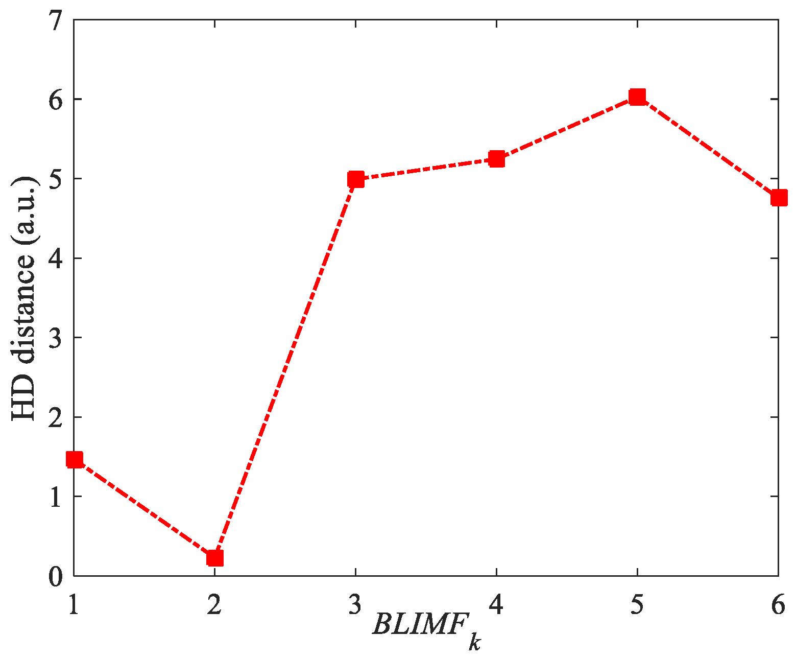
2.2. VMD-Based Denoising Theory

Since no additional detectors were used in our system, the signal-to-noise ratio of original self-mixing interference signals was low, and VMD-based noise reduction pre-processing was necessary for the subsequent phase extraction process. Let ∆V(t) be the original multicomponent signal, where the VMD algorithm uses the Wiener filter to treat the variational problem of ∆V(t). This method is capable of adaptively decomposing ∆V into a discrete number of sub-signals ∆Vk. These sub-signals are called the band-limited intrinsic mode functions (BLIMFs), which are amplitude-modulated–frequency-modulated (AM-FM) signals. Generally, the BLIMFs can be written as follows:
min { Δ V k } , { ω k } k = 1 K t δ ( t ) + j π t Δ V k ( t ) e j ω k t 2 , s . t . k = 1 K Δ V k = Δ V ( t )
where ∆Vk represents the kth modal component with its central frequency ωk; is the convolution operator; δ(t) denotes the unit impulse function; and t is the partial derivative with respect to t. The optimal solution for the variational problem could be obtained by introducing the quadratic penalty function α and Lagrange multiplier λ:
L ( { Δ V k } , { ω k } , λ ) = α k = 1 K t δ ( t ) + j π t Δ V k ( t ) e j ω k t 2    + Δ V ( t ) k = 1 K Δ V k ( t ) 2 2 + λ ( t ) , Δ V ( t ) k = 1 K Δ V k ( t )
where L denotes the augmented Lagrangian, and the saddle point of L could be obtained by constantly updating the values of Δ V k n + 1 , ω k n + 1 , and λ k n + 1 in a sequence of iterative sub-optimizations using the alternate direction method of multipliers. The updated procedure can be expressed as follows:
Δ V ^ k n + 1 ( ω ) = Δ V ^ ( ω ) i < k Δ V ^ i n + 1 ( ω ) i > k Δ V ^ i n ( ω ) + λ ^ n ( ω ) / 2 1 + 2 α ( ω ω k n ) 2
ω k n + 1 = 0 ω Δ V ^ k n + 1 ( ω ) 2 d ω 0 Δ V ^ k n + 1 ( ω ) 2 d ω
λ ^ n + 1 ( ω ) = λ ^ n ( ω ) + τ Δ V ^ ( ω ) k = 1 K Δ V ^ i n + 1 ( ω )
where Δ V ^ k n ( ω ) is the Fourier transform of each mode; n represents the iteration number.
In our experiment, the acquired signal ∆V’(t) that is composed of a noise-free function ∆V(t) and a pure noise signal n(t) can be expressed by the following:
Δ V ' t = Δ V t + n t
Using the above-mentioned VMD method, we can expand ∆V’(t) into a superposition of a series of BLIMFs ranging from low frequency to high frequency, and this process is shown as follows:
Δ V ' t = k = 1 m B L I M F k + k = m + 1 K B L I M F k + ο t
where ο(t) is the residual component of the decomposition; BLIMF1~BLIMFm are the low-frequency intrinsic mode components, and BLIMFm+1~BLIMFK denote the high-frequency parts. This process allowed us to find the most relevant modes with which to estimate Δ V ^ ( t ) from a noisy signal ∆V’(t) as follows:
Δ V ^ t = k = 1 J B L I M F k t
where J( 1 J K ) represents the relevant modalities index. In order to determine the optimal correlated modes, the probability density function (PDF) of the acquired signal and all BLIMFs are calculated by means of a kernel smoothing density function, respectively. The PDF can describe the probability distribution of the signal, giving more statistical characteristics rather than the knowledge of frequency. From these PDFs, the Hausdorff distance was utilized to perform the similarity measure between noisy signal ∆V’(t) and each intrinsic mode component:
L k = H D P D F Δ V ' , P D F B L I M F k    = max D P D F Δ V ' , P D F B L I M F k , D P D F B L I M F k , P D F Δ V '
with
D P D F Δ V ' , P D F B L I M F k = max       min x P D F Δ V '     y P D F B L I M F k x y
Through these equations, the Hausdorff distance between the noisy signal ∆V’(t) and each intrinsic mode component is available, and it is possible to extract the most relevant modes to recover the original signal. And the most relevant modality index J can be calculated by evaluating the HD variation between two adjacent BLIMFs. Since the significant increase in the HD indicates a weakened correlation between the BLIMF and the original signal, the most relevant modality index J can be obtained using the following equation:
J = max L k + 1 L k , 1 k K 1
Therefore, the estimation signal Δ V ^ ( t ) can be obtained through Equation (13).

2.3. Orthogonal Phase Demodulation Algorithm Based on Hilbert Transform

After the denoising procedure, the self-mixing signal appears to be a cosine function with regard to the measured phase φn(t). In order to perform precision phase measurements, it is necessary to obtain the corresponding orthogonal components from the interference signal. The Hilbert transform (HT), as a kind of integral transformation, has been used to analyze the instantaneous attributes of the self-mixing signal. The HT of the self-mixing signal is defined by an integral transform as follows:
H Δ V ( t ) = 1 π + Δ V ( t ) t τ d τ = Δ V ( t ) * 1 π t
Equation (17) shows that the time-domain signal ∆V(t), after the Hilbert transform, is equivalent to calculating its convolution with the impulse response function h(t) = 1/πt. Since the frequency of the self-mixing signal is ω = /dt, the frequency response after HT could be written as follows:
H ω = j , ω > 0 0 , ω = 0 + j , ω < 0
That is to say, the HT is equivalent to a filter, in which the magnitudes of the spectral components remain the same while their phases are shifted −π/2 or +π/2 with the sign of frequency. In our case, the object vibrated, which produced periodic changes in both the direction of motion and the instantaneous frequency. Due to the basic nature of the self-mixing interference effect, which means that the direction of the target’s motion can be distinguished through the inclination of the interferometric fringe, it is possible to find the reverse point of the self-mixing signal. After that, the HT is performed one and three times for the self-mixing signal on both sides of the reverse point, respectively [24], generating a quadrature signal Δ V ˜ ( t ) . And the measured phase φn(t) from each measurement channel can be calculated in the same way as follows:
φ n t = arctan Δ V ˜ n ( t ) Δ V n ( t )
Combining with individual lasing wavelength, the vibration of the object Ln(t) can be reconstructed as follows:
L n t = λ n 4 π φ n t

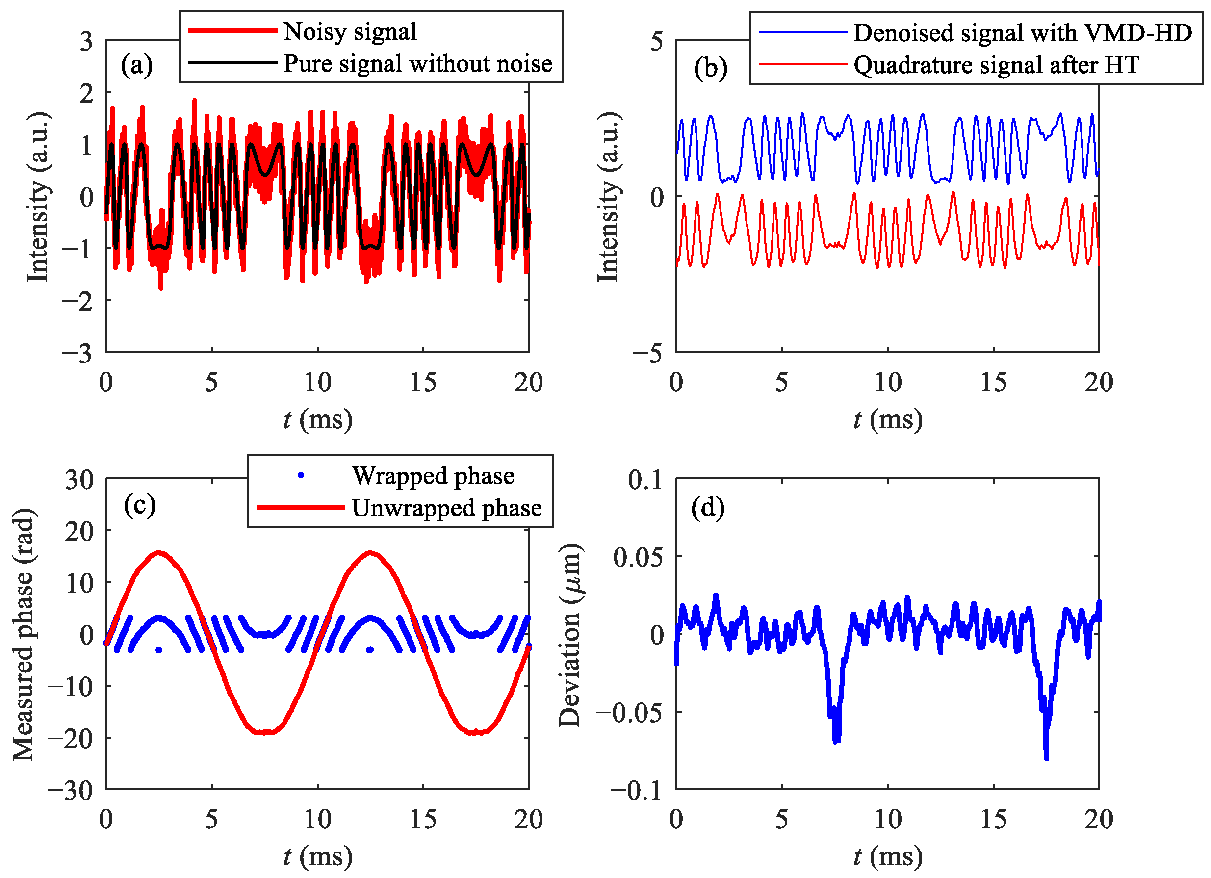
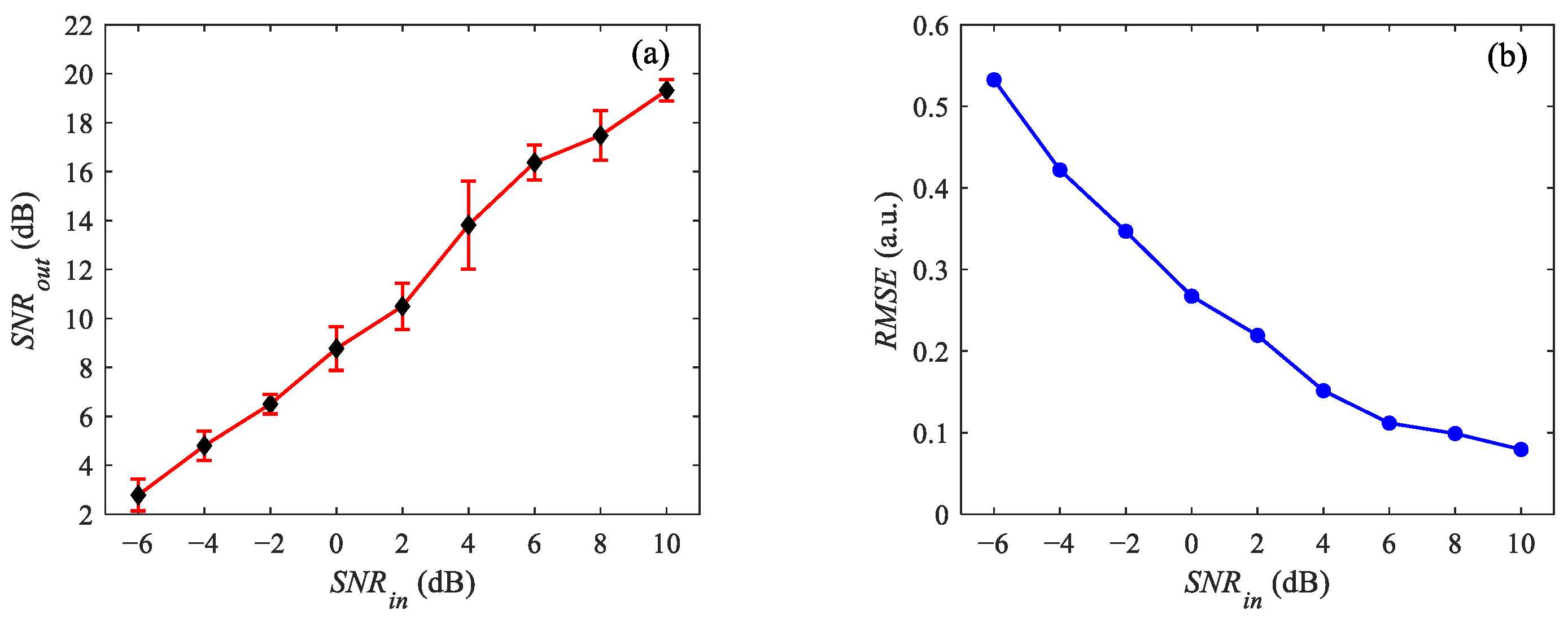
3. Simulation Results

To verify the validity of the proposed method, a typical SMI signal was generated as the original signal. The lasing wavelength for the VCSEL is 850 nm; the optical feedback parameter and linewidth enhancement factor are 0.5 and 3, respectively. The object vibrates with an amplitude of 1.2 μm and a frequency of 100 Hz at an equilibrium position of 0.02 m. Meanwhile, a white Gaussian noise is added to the SMI signal, and the SNRin is set to 9 dB. Using VMD analysis, the noisy signal is expanded into six BLIMFs, and Figure 2 shows the probability distribution of the six decomposed BLIMFs (represented by the red dotted line) compared to the original noisy signal (represented by the blue line). It can be seen that the probability distributions of BLIMF1 and BLIMF2 are closest to the original signal. In other words, the BLIMFs with the higher orders are considered to be less relevant.
Since the geometric distance can effectively evaluate the similarity between the two datasets, the HDs between the original signal and each BLIMF were calculated and are shown in Figure 3. The HDs for the BLIMF1 and BLIMF2 were much shorter than the other BLIMFs, and they increased sharply with an increase in the order of BLIMFs. As a result, the HDs helped to efficiently identify and select the BLIMF1 and BLIMF2 with the most relevant modes for the further reconstruction of the original signal.
After the filtering based on the VMD-HD method, the vibration of the object was retrieved by the HT orthogonal phase demodulation algorithm, and the simulation results are shown in Figure 4. Figure 4a demonstrates both the noisy and noise-free self-mixing interference signals, respectively. The VMD-HD denoised signal, together with the HT-generated quadrature signal, are shown in Figure 4b. The signal processed by the proposed method was smoother and similar to the pure signal. By comparing these two orthogonal parts, the phase of the object can be retrieved, as shown in Figure 4c. Figure 4d presents the deviation between the reconstructed and the original vibration waveform; the maximum reconstruction error is 0.0785 μm with a measurement standard deviation of 0.0179 μm.
To evaluate the denoising performance of the VMD-HD method, two metrics, the output signal-to-noise ratio (SNRout) and the root-mean-square error (RMSE), were introduced for the quantitative analysis. They are defined as follows:
S N R o u t = 10 log n = 1 N Δ V 2 n n = 1 N [ Δ V ^ n Δ V n ] 2
R M S E = 1 N n = 1 N [ Δ V ^ n Δ V n ] 2
where N represents the total number of the sampling points. The mean value of the 10 sets of simulated data at SRNin = 9 dB was calculated to be 18.449 dB for SNRout and 0.081 for RMSE. To further validate the robustness of the algorithm, the SNRout and RMSE for 90 sets of simulation data with SRNin values ranging from −6 dB to 10 dB were conducted, and the results are presented in Figure 5. The SNRout experienced an elevation of roughly 16 dB, indicating that the reconstructed results became more stable and focused. On the other hand, the value of RMSE decreased as the SRNin increased. When input signal-to-noise ratios varied from −6 dB to 10 dB, the corresponding RMSE values were 0.532, 0.422, 0.346, 0.267, 0.219, 0.151, 0.111, 0.098 and 0.079, respectively, further indicating that the proposed method effectively retains useful information from the original signal.

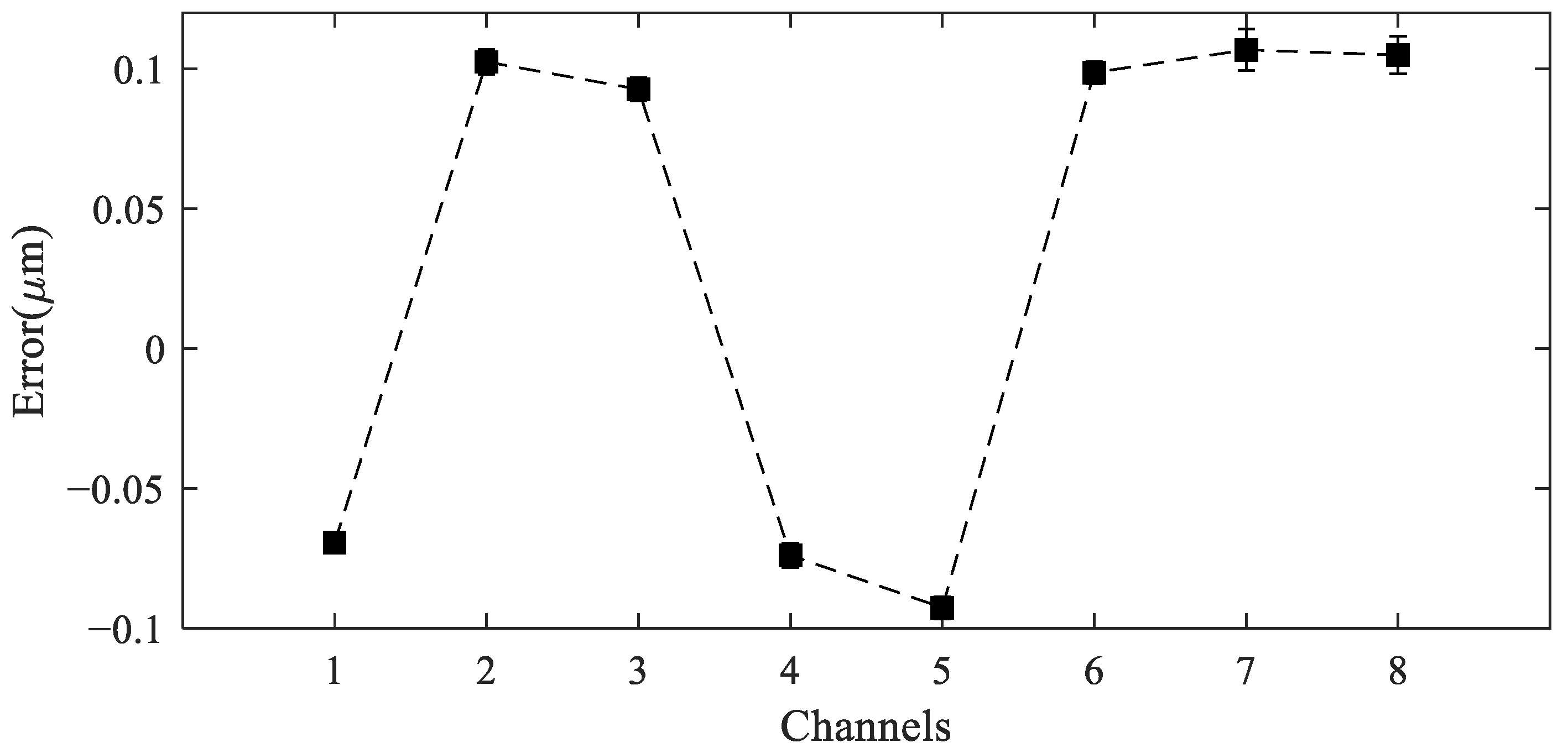
4. Experimental Results

Figure 6 demonstrates the experimental setup for the self-mixing vibrometer based on the VCSEL array. The overall system can be mainly divided into three parts: the optical part, the electronic part, and the signal processing part.
In the optical part, eight 850 nm VCSELs (LD0850-B010, manufactured by Brightphoton Technologies Co., Shenzhen, China), each outlined by a transistor and equipped with an individual aspheric collimating lens of 7 mm in focal length, are arranged in a 1 × 8 parallel configuration on a substrate mold. The spacing between the centers of each laser diode is 7 mm. The typical threshold current for each VCSEL is approximately 1.3 mA, with a corresponding optical output power of 4 mW. The single-mode polarized laser beams emitted from the VCSEL array are positioned vertically onto an aluminum membrane, which is covered by a reflective coating and securely attached to a loudspeaker. In our scenario, the four corners of the aluminum diaphragm are riveted using studs, allowing the tensioned film to scatter a portion of each laser beam back into the VCSEL’s resonator, generating the self-mixing interference. The SMI signal is captured by monitoring the variation in the junction voltage at each diode. The acquired eight-channel signals are amplified using parallel low-noise AC-coupled instrumentation amplifiers and then sampled by an A/D converter. The sampled data are subsequently fed into a PC for further signal processing. A LabVIEW program is developed to implement the VMD-HD noise reduction and HT-based phase reconstruction algorithm in real time.
Three sets of experiments in which the speaker was excited by sinusoidal voltages with varying amplitudes and frequencies were conducted. Specifically, the driving signals for the comparison experiments were set to 50 Hz and 100 mVpp, 100 Hz and 100 mVpp, and 100 Hz and 150 mVpp, respectively. Figure 7 illustrates the three sets of eight-channel self-mixing interference signals after VMD-HD filtering. Each measurement channel’s signal exhibited a high signal-to-noise ratio and stable fringe visibility, laying a solid foundation for subsequent phase measurements.
From the distribution of SMI signals, it is evident that, under the same driving signal, the number of self-mixing interference fringes varied across different locations on the target. Specifically, as one approached the center of the diaphragm, the vibrating amplitude increased, and the fringes became denser. The vibration pattern of the diaphragm remained consistent for measurement points that were symmetrical about the diaphragm’s center. Additionally, even at identical locations, the performance differed under different driving signals. Augmentation in either the driving amplitude or frequency led to an increase in the number of fringes.
In order to analyze the vibration of each measurement point on the diaphragm, the vibrating waveforms from all the sensing channels were reconstructed using the proposed method shown in Figure 8. Not only the amplitude but also the phase of the vibration at each point of the target varied with different driving signals. The phase at the intermediate points remains almost in phase for different driving signals, while the points near the edges may vibrate in an anti-phase. Furthermore, the amplitude and frequency characteristics of the reconstructed vibration waveforms were analyzed and are shown in Figure 9. As the frequency of the excitation signal increased, the measurement results from all channels shifted toward higher frequencies correspondingly. Simultaneously, the augmentation in the amplitude of the excitation signal aligned with the variation pattern of the reconstructed target vibration amplitude.
When the sinusoidal driving voltage was set to 100 Hz and 150 mVpp, the same vibration was recorded by a commercial vibrometer (Polytec, OFV-5000, Waldbronn, Germany) as well. The amplitudes of the vibration at each point were measured over ten consecutive periods and compared with the results obtained from the reference vibrometer. The measured deviations are depicted in Figure 10. The black square represents the difference between the calibration peak amplitude and the measured results. The mean value of the difference and the standard deviation are 91.4 nm and 4.6 nm, respectively, indicating that the recovered vibration waveform is a good reproduction of the vibration at each point.

5. Discussion

The above experimental results validate the practicability of the developed vibrometer based on an array of self-mixing VCSELs. By comparing our measured results with a commercial Polytec vibrometer, the maximum measurement error obtained was about 107.2 nm. From Equation (20), the systematic errors stem from the demodulation algorithm, the stability of the lasing wavelength, and the changes in the refractive index of the air. Moreover, Polytec’s calibration errors need to be taken into account as well. Therefore, the uncertainty of the proposed system can be expressed as follows:
δ Δ L = λ 4 π δ φ 2 + Δ L λ δ λ 2 + Δ L n δ n 2 + δ L r e f 2
Theoretically, the measured phase in our system can be established with almost arbitrary precision. However, it suffers from the signal-to-noise ratio after the VMD-HD denoising process. The VMD-HD has a strong denoising ability to reduce the Gaussian white noise from the measured signal, but the missing detailed information causes measurement deviation. For a typical micrometer-scale vibration measurement, numerical analysis was conducted to evaluate the uncertainty of the measured phase under different signal-to-noise ratio conditions. We evaluated the measurement results of the VMD-HD method with an SNRin that varied from −6 to10 dB, while the reconstructed results without any noise reduction processing were provided as well. It is beyond question, as shown in Figure 11, that the proposed VMD-HD method obtained better measurement results. When SNRin = 10 dB, the vibrating measurement error with the VMD-HD method achieved 0.0895 μm, and the corresponding standard deviation was 0.0180 μm. By comparison, without the denoising process, the measurement error and standard deviation were 0.967 μm and 0.205 μm, respectively. The VMD-HD algorithm used adaptive parameter selection to make sure that the signal decomposed with lower energy loss. Even in the low SNR scenarios of SNRin = −6 dB, the reconstructed error was 2.833 μm, which is much better than 13.691 μm where no denoising process was adopted. The measurement results obtained more improvements using the proposed method, while the measured signal had a lower SNR. The typical signal-to-noise ratio for measuring signals was about 10 dB in our experiment, and the measurement uncertainty was estimated to be in the order of 0.1 μm.
The VCSEL used in our experiments had high thermal stability, and the typical wavelength drift with regard to the temperature was about 0.07 nm/K. During the measurement, the temperature variation in the VCSELs was controlled below 0.1 K through a TEC controller and the lasing wavelength induced uncertainty at 8.2 × 10⁻⁶L.
The change in air refractivity caused by the environmental conditions deviated from the initial work state. By omitting the air contents variation, the change in the air reflectivity could be obtained through the Edlen equation as follows:
δ n = 0.00268 ( P P 0 ) 0.929 ( T T 0 ) 0.00042 ( f f 0 ) × 10 6
where P0, T0, and f0 denote the initial air pressure, temperature, and humidity of the measurement environment, while P, T, and f are the actual experimental conditions. In our laboratory, the humidity and air pressure are kept constant, and a fluctuation of about 1 K of the room temperature contributes to a change in the refractive index of air, resulting in a displacement measurement error of 0.929 × 10⁻⁶L.
Based on the instruction of the Polytec-OFV-5000 vibrometer used for the calibration experiments, the uncertainty of the instrument is 1.5 nm within a motion range of 5 μm. Taking all the uncertainties into consideration, the comprehensive measurement uncertainty of the order 0.1 μm was obtained when the measured vibration amplitude was less than 5 μm, which is in good agreement with the experimental results. The performance of the developed interferometer is currently limited by the signal-to-noise ratio of the self-mixing interference signal. We believe that the solution could be further improved using better noise reduction technology.

6. Conclusions

In summary, a multi-channel vibration measurement system based on a self-mixing VCSEL array has been implemented. The system uses a 1 × 8 VCSEL array to simultaneously irradiate different positions of a vibrating target, and the backscattered light is fed back to individual VCSELs to form parallel self-mixing measurement channels. The self-mixing interference signals are obtained through the junction voltage of each VCSEL, and a filtering algorithm based on variational modal decomposition and Hausdorff distance is proposed to improve the signal-to-noise ratio. Furthermore, the Hilbert quadrature phase demodulation algorithm is utilized to retrieve the phase of the self-mixing interference signals. The experimental results show that the reconstructed vibration waveforms match closely with the data from a reference Polytec vibrometer, and the error sources that influenced the measurement resolution are discussed as well. These results show that the development of the self-mixing vibrometry based on the VCSEL array is useful to achieve multi-point vibration sensing with high resolution, providing a new powerful tool for multi-dimensional vibration measurement in a variety of industrial applications.

Author Contributions

Conceptualization, Z.Q., D.G. and M.W.; methodology, W.X. and H.H.; software, J.Y. and S.S.; validation, D.G. and W.X.; writing—original draft preparation, J.Y., S.S. and W.X.; writing—review and editing, Z.Q., D.G. and M.W.; visualization, W.X. and H.H.; supervision, D.G. and M.W.; project administration, D.G.; funding acquisition, W.X., D.G. and Z.Q. All authors have read and agreed to the published version of the manuscript.

Funding

This research was funded by the National Natural Science Foundation of China (NSFC) (grant number 51775283, 51875292) and Science and Technology Plan Projects of Jiangsu Provincial Market Supervision and Administration Bureau (grant number KJ2023018).

Institutional Review Board Statement

Not applicable.

Informed Consent Statement

Not applicable.

Data Availability Statement

The raw data supporting the conclusions of this article will be made available by the authors on request.

Conflicts of Interest

The authors declare no conflicts of interest.

References

  1. Wei, Y.C.; Weng, J.C.; Chen, B.; Gao, Z.R.; Miao, H.; Yu, Q.F.; Fu, Y. Interferometric-scale full-field vibration measurement by a combination of digital image correlation and laser vibrometer. Opt. Express 2024, 32, 20742–20761. [Google Scholar] [CrossRef] [PubMed]
  2. Rothberg, S.J.; Allen, M.S.; Castellini, P.; Di Maio, D.; Dirckx, J.J.J.; Ewins, D.J.; Halkon, B.J.; Muyshondt, P.; Paone, N.; Ryan, T.; et al. An international review of laser Doppler vibrometry: Making light work of vibration measurement. Opt. Lasers Eng. 2017, 99, 11–22. [Google Scholar] [CrossRef]
  3. Li, P.G.; Fang, Q.; Yu, H.B.; Guo, R.X.; Xia, H.T. Full-field displacement measurements of structural vibrations using a novel two-stage neural network. Measurement 2025, 242, 115884. [Google Scholar] [CrossRef]
  4. Albert, A.; Donati, S.; Lee, S.-L. Self-Mixing Interferometry on Long Distance: Theory and Experimental Validation. IEEE Trans. Instrum. Meas. 2024, 73, 1–8. [Google Scholar] [CrossRef]
  5. Hua, Z.Y.; Wang, Y.F.; Wang, Q.; Fu, S.Y.; Tan, Y.D. Rotational Doppler effect of vortex beam with frequency-shifted laser feedback. Opt. Laser Eng. 2024, 178, 108223. [Google Scholar] [CrossRef]
  6. Taimre, T.; Nikolić, M.; Bertling, K.; Lim, Y.L.; Bosch, T.; Rakić, A.D. Laser feedback interferometry: A tutorial on the self-mixing effect for coherent sensing. Adv. Opt. Photon 2015, 7, 570–631. [Google Scholar] [CrossRef]
  7. Li, D.Y.; Li, Q.H.; Jin, X.; Xu, B.; Wang, D.; Liu, X.P.; Zhang, T.T.; Zhang, Z.H.; Huang, M.L.; Hu, X.H.; et al. Quadrature phase detection based on a laser self-mixing interferometer with a wedge for displacement measurement. Measurement 2022, 202, 111888. [Google Scholar] [CrossRef]
  8. Zhang, P.; Tan, Y.D.; Liu, N.; Wu, Y.; Zhang, S.L. Phase difference in modulated signals of two orthogonally polarized outputs of a Nd:YAG microchip laser with anisotropic optical feedback. Opt. Lett. 2013, 38, 4296–4299. [Google Scholar] [CrossRef]
  9. Ge, L.; Yang, N.; Wang, J.; Li, Y.Y.; Chu, W.D.; Duan, S.Q.; Xie, Y. Properties of self-mixing interference in terahertz distributed feedback quantum cascade lasers. Appl. Phys. Lett. 2019, 115, 261105. [Google Scholar] [CrossRef]
  10. Xie, Z.W.; Zhang, M.; Li, J.; Xia, W.; Guo, D.M. All-Fiber Laser Feedback Interferometry for Sequential Sensing of In-Plane and Out-of-Plane Displacements. Photonics 2023, 10, 480. [Google Scholar] [CrossRef]
  11. Deleau, C.; Seat, H.C.; Surre, F.; Zabit, U.; Jayat, F.; Bosch, T.; Bernal, O. Optical Feedback FM-to-AM Conversion with Photonic Integrated Circuits for Displacement Sensing Applications. J. Light. Technol. 2024, 42, 3446–3453. [Google Scholar] [CrossRef]
  12. Wang, X.; Yang, H.; Hu, L.; Li, Z.; Chen, H.; Huang, W. Single Channel Instrument for Simultaneous Rotation Speed and Vibration Measurement Based on Self-Mixing Speckle Interference. IEEE Photonics J. 2022, 14, 6802405. [Google Scholar] [CrossRef]
  13. Zhao, Y.; Xiang, R.; Huang, Z.; Chen, J.; Zhai, L.; Wang, X.; Ma, Y.; Yu, B.; Lu, L. Research on the multi-longitudinal mode laser self-mixing static angle-measurement system using a right-angle prism. Measurement 2020, 162, 107906. [Google Scholar] [CrossRef]
  14. Liao, J.-R.; Cheng, J.-M.; Hsiao, V.K.S. Enhanced vibration measurement through frequency modulated laser diode self-mixing interferometry. Appl. Phys. B-Lasers Opt. 2024, 130, 173. [Google Scholar] [CrossRef]
  15. Donati, S. Vibration Measurements by Self-Mixing Interferometry: An Overview of Configurations and Benchmark Performances. Vibration 2023, 6, 625–644. [Google Scholar] [CrossRef]
  16. Contreras, V.; Toivonen, J.; Martinez, H. Enhanced self-mixing interferometry based on volume Bragg gratings and laser diodes emitting at 405-nm wavelengths. Opt. Lett. 2017, 42, 2221–2223. [Google Scholar] [CrossRef]
  17. Contreras, V.; Lonnqvist, J.; Toivonen, J. Edge filter enhanced self-mixing interferometry. Opt. Lett. 2015, 40, 2814–2817. [Google Scholar] [CrossRef] [PubMed]
  18. Norgia, M.; Melchionni, D.; Donati, S. Exploiting the FM-Signal in a Laser-Diode SMI by Means of a Mach–Zehnder Filter. IEEE Photon-Technol. Lett. 2017, 29, 1552–1555. [Google Scholar] [CrossRef]
  19. Tucker, J.R.; Mowla, A.; Herbert, J.; Fuentes, M.A.; Freakley, C.S.; Bertling, K.; Lim, Y.L.; Matharu, R.S.; Perchoux, J.; Taimre, T.; et al. Self-mixing sensing system based on Uncooled vertical-cavity surface-emitting laser array: Linking multichannel operation and enhanced performance. Opt. Lett. 2014, 39, 394–397. [Google Scholar] [CrossRef]
  20. Lim, Y.L.; Nikolic, M.; Bertling, K.; Kliese, R.; Rakić, A.D. Self-mixing imaging sensor using a monolithic VCSEL array with parallel readout. Opt. Express 2009, 17, 5517–5525. [Google Scholar] [CrossRef]
  21. Lim, Y.L.; Kliese, R.; Bertling, K.; Tanimizu, K.; Jacobs, P.A.; Rakić, A.D. Self-mixing flow sensor using a monolithic VCSEL array with parallel readout. Opt. Express 2010, 18, 11720–11727. [Google Scholar] [CrossRef] [PubMed]
  22. Dragomiretskiy, K.; Zosso, D. Variational Mode Decomposition. IEEE Trans. Signal Proces. 2014, 62, 531–544. [Google Scholar] [CrossRef]
  23. Ren, M.J.; Zhang, H.W.; Jiang, P.B.; Zhao, Y.; Xue, L.F.; Ren, G.J.; Shi, W.; Yao, J.Q. All-fiber hybrid displacement-sensing system based on self-mixing interference and intracavity spectroscopy. Opt. Commun. 2022, 505, 127578. [Google Scholar] [CrossRef]
  24. Zhang, Z.H.; Li, C.W.; Huang, Z. Vibration measurement based on multiple Hilbert transform for self-mixing interferometry. Opt. Commun. 2019, 436, 192–196. [Google Scholar] [CrossRef]
Figure 1. Schematic diagram of the multi-channel SMI based on the VCSEL array.
Photonics 12 00178 g001
Figure 2. The PDF of the noisy SMI signals and the six decomposed modes: (af) the PDF comparison diagrams of BLIMF1~BLIMF6 with the original signal, respectively.
Photonics 12 00178 g002
Figure 3. The HD of each intrinsic mode with respect to the original signal.
Photonics 12 00178 g003
Figure 4. Simulation results: (a) the noisy and noise-free SMI signals; (b) the filtered and quadrature signals; (c) the reconstructed unwrapped phase; and (d) measurement deviation.
Photonics 12 00178 g004
Figure 5. Simulation results for the denoising performance with SNRin ranging from −6 dB to 10 dB: (a) SNRout; (b) RMSE.
Photonics 12 00178 g005
Figure 6. Experimental setup for the self-mixing vibrometer based on the VCSEL array.
Photonics 12 00178 g006
Figure 7. Experimental 8-channel SMI signals when the speaker is excited by different sinusoidal waves: (a) 50 Hz and 100 mVpp; (b) 100 Hz and 100 mVpp; and (c) 100 Hz and 150 mVpp.
Photonics 12 00178 g007
Figure 8. Reconstructed vibration curves for each position of the target with different driving signals: (a) 50 Hz and 100 mVpp; (b) 100 Hz and 100 mVpp; and (c) 100 Hz and 150 mVpp.
Photonics 12 00178 g008
Figure 9. The amplitude–frequency characteristic of the reconstructed 8-channel vibration waveforms under different driving conditions.
Photonics 12 00178 g009
Figure 10. The deviation between the measurement results from the VCSEL array interferometer and Polytec OFV-5000 vibrometer.
Photonics 12 00178 g010
Figure 11. Comparison of measurement results using the VMD-HD method and without using the VMD-HD method on the noisy synthetic signals with SNRin ranging from −6 dB to 10 dB.
Photonics 12 00178 g011
Disclaimer/Publisher’s Note: The statements, opinions and data contained in all publications are solely those of the individual author(s) and contributor(s) and not of MDPI and/or the editor(s). MDPI and/or the editor(s) disclaim responsibility for any injury to people or property resulting from any ideas, methods, instructions or products referred to in the content.

